


4-57
Cisco ONS 15454 DWDM Installation and Operations Guide, R6.0
September 2005
Chapter 4 Perform Node Acceptance Tests
DLP-G94 Verify Add and Drop Connections on OADM Node with OSC-CSM Cards
Step 8
Change the administrative state of the drop BAND TX port related to the wavelength selected on the
tunable laser to OOS,MT.
Step 9
(Optional) Connect a power meter to the proper 15xx.xs TX port on the front panel (the dual port
compared with the port where the tunable laser is connected). Verify that the physical optical power
value from that port is consistent with the value displayed on the Provisioning > Optical Chn >
Parameters tab for the proper CHAN TX power value, +/– 0.5 dB.
Step 10
Verify the west AD-xC-xx.x (west-to-east) card:
a.
Display the west AD-xC-xx.x card in card view.
b.
Click the
Provisioning > Optical Chn > Parameters
tabs.
c.
Verify that the Power value of the CHAN TX port is higher than the default no-power value of
–35 dBm.
d.
Display the east AD-xC-xx.x card in card view.
e.
Click the
Provisioning > Optical Chn > Parameters
tabs.
f.
Verify that the power value for the CHAN TX port is higher than the default no-power value of
–35 dBm.
g.
If the AD-xC-xx.x card is an AD-4C-xx.x card, a VOA (applied to all four channels) is installed
along the drop path and needs to be activated in Step
h.
Change the Admin State of the CHAN TX port related to the wavelength selected on the tunable
laser to
OOS,MT
(ANSI) or
Locked,maintenance
(ETSI). Click
Apply
.
i.
Perform the output power check.
Step 11
(Optional) Connect a power meter to the proper 15xx.xx TX port on the front panel (the dual port
compared with the port where the tunable laser is connected). Verify that the physical optical power
value from that port is consistent with the value on Provisioning > Optical Chn > Parameters tab for the
proper CHAN TX power value, +/– 0.5 dB.
Step 12
Repeat Steps
through
for all add paths of any west AD-xC-xx.x or 4MD-xx.x cards along the
east-to-west direction.
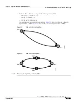
Step 13
Remove the loopback on the west OSC-CSM card.
Step 14
In node view, click the
Provisioning > WDM-ANS > Port Status
tabs.
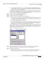
Step 15
Click
Launch ANS
.
Step 16
Create a loopback on the east OSC-CSM card by connecting the OSC-CSM LINE RX and LINE TX
ports using a patchcord and 10-dB bulk attenuator.
Step 17
Verify that the OSC link becomes active on the west OSC-CSM card. (The OSC termination must be
already provisioned. If not, complete the
“NTP-G38 Provision OSC Terminations” procedure on
Note
Due to the OSC signal loopback, an SDCC Termination Failure alarm might be raised.
Step 18
If the OSC link becomes active, continue with
. If the OSC link does not turn up, perform the
following troubleshooting steps:
a.
Remove the 10-dB bulk attenuator between the LINE TX and LINE RX connection. If the OSC link
becomes active, continue with
. If not, continue with Step
b.
Modify the OSC Fail Low thresholds. Click the
Provisioning > Optical Line > Optics Thresholds
tabs and change the Port 6 opwrMin (minimum power) to –40 dBm.
Summary of Contents for ONS 15454 DWDM
Page 38: ...Figures xxxviii Cisco ONS 15454 DWDM Installation and Operations Guide R6 0 August 2005 ...
Page 54: ...Procedures liv Cisco ONS 15454 DWDM Installation and Operations Guide R6 0 August 2005 ...
Page 64: ... 64 Cisco ONS 15454 DWDM Installation and Operations Guide R6 0 August 2005 Chapter ...


