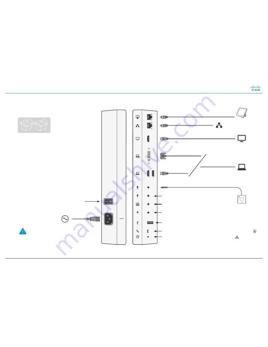
Installing Cisco TelePresence MX200 G2 - Wall Mount
78-100249-02A0 | JUNE 2016 | © 2016 Cisco Systems, Inc. All rights reserved.
5
3
Connect the cables
For maintenance only
Reset to factory
settings
Audio line output
Always use the provided
power cable.
The wall socket outlet must
be easily accessible after
installation.
Power switch
Audio line input
LAN
1
Video input
2
(e.g. PC)
Video output
2
(e.g. 2
nd
display)
Power
(100-240 VAC,
50/60 Hz)
Touch
controller
1
USB, for future use
HDMI
DVI-I
Microphone
3
2
nd
microphone
2, 3
C
D
1
Use the cable that is labeled with
for the Touch controller; use the cable
that is labeled with for the LAN
2
Optional
3
Always use the provided Cisco
TelePresence Table Microphone 20


