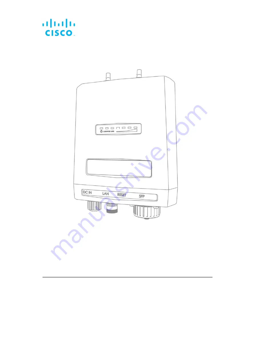
Cisco Ultra-Reliable Wireless
Backhaul FM4200 Fiber
Installation and Configuration Manual
(Formerly Fluidmesh)
Model FM4200F | Edition 1.14 | Firmware 8.5.0
Page 1: ...Cisco Ultra Reliable Wireless Backhaul FM4200 Fiber Installation and Configuration Manual Formerly Fluidmesh Model FM4200F Edition 1 14 Firmware 8 5 0 ...
Page 2: ...r countries To view a list of Cisco trademarks go to this URL www cisco com go trademarks Third party trademarks mentioned are the property of their respective owners The use of the word partner does not imply a partnership relationship between Cisco and any other company 1110R 2018 2021 Cisco Systems Inc All rights reserved ...
Page 3: ...sh Network Architecture 19 3 2 5 Point To Multipoint Architecture With FluidMAX 20 3 3 Cisco Network Addressing 22 3 3 1 Bridge IP Addressing 22 3 3 2 Unit Identification And Addressing 22 Mesh And Bridge Capable Radio Transceiver Identification 22 Operating The Unit In Mesh Point Mode Or Mesh End Mode 23 Network Addressing 24 Cisco Radio Transceivers 24 Connecting And Configuring An Ethernet Edge...
Page 4: ...des 53 6 4 Using The RACER Radio Configuration Interface 54 6 5 Viewing The Technical Documentation For Your Cisco Device 54 7 Device Configuration Using The Configurator Interface 55 7 1 Software And Hardware Prerequisites 57 7 2 Accessing The Cisco FM4200 Fiber For Device Configuration 57 7 2 1 Local Access And Login For Initial Configuration 58 7 2 2 Initial Configuration With The Unit In Provi...
Page 5: ... Setting 106 Using The Maximum Link Length Setting 107 7 6 2 SFP Settings 108 7 6 3 Static Routes 108 7 6 4 Pass Lists And Block Lists 109 7 6 5 Multicast 113 Multicast Management For Mesh Network Capable Devices 113 Configuring Multicast Within A Layer 3 Network 115 7 6 6 SNMP Configuration 116 Using SNMP V2c 117 Using SNMP V3 118 7 6 7 Wireless Access Point Configuration 120 7 6 8 RADIUS Configu...
Page 6: ...nistrator Password 170 9 4 The Wireless Link Is Poor Or Non Existent In Bridge Mode 171 10 Electrical Power Requirements 172 11 Heat Radiation Data 175 12 Federal Communications Commission FCC Radio Interference Statement 177 13 Notices And Copyright 180 14 Cisco End User License Agreement 182 14 1 Preamble 182 14 2 Notice 182 14 3 Definitions 182 14 4 License Grant 183 14 5 Uses And Restrictions ...
Page 7: ...at there is no link between adverse health effects and exposure at or under the current RF energy exposure limit and that the current FCC RF exposure limits are sufficient to insure the safety of users If any Cisco hardware unit breaks down or malfunctions emits smokeor an unusual smell if water or other foreign matter enters the unit enclosure or if the unit is dropped onto a hard surface or dama...
Page 8: ...on and is designed specifically to assure the long term durability and reliability of compatible radio transceivers that have been installed in outdoor environments If you need further information regarding the recommended usage of FM SHIELD contact your Cisco Networks representative Relevant technical specifications for FM SHIELD can be found in the Cisco FM SHIELD installation manual HAZARDOUS C...
Page 9: ...o transceivers or 21cm 8 3 in all FM1300 Otto and x500 radio transceivers Canada This system has been evaluated for RF exposure for humans in accordance with ISED regulation RSS 102 To maintain compliance the minimum separation distance from the antenna to general bystanders is 20cm 7 9in for all Cisco radio transceivers Europe Australia New Zealand This system has been evaluated for RF exposure f...
Page 10: ... sources that may cause temporary or permanent blindness For additional guidance regarding the safe use of laser based and LED based fiber optic technology refer to ANSI Z136 2 Safe Use of Optical Fiber Communication Systems Utilizing Laser Diode and LED Sources IMPORTANT The Cisco FM4200 Fiber is not shipped from the factory with fiber optic transceivers installed unless the fiber optic transceiv...
Page 11: ...and gateway unit enclosures may become hot during normal operation During normal operation do not touch or handle the unit enclosure without personal protective equipment HAZARDOUS CONDITION WARNINGS 2021 Cisco and or its affiliates All rights reserved Page 11 of 189 ...
Page 12: ...l If you find any mistakes or if you know of a way to improve the procedures that are given please let us know by E mailing your suggestions to documentation cisco com Reporting mistakes and recommending improvements 2021 Cisco and or its affiliates All rights reserved Page 12 of 189 ...
Page 13: ...ble service in high speed applications for example servicing extremely fast moving trains and must be connected to one or more external antennas The unit is designed primarily for mobility applications based on Fluidity technology in which specialized antennas need to be deployed for example train to ground automated mining vehicles industrial automation and similar applications The Cisco FM4200 F...
Page 14: ...If a newer network is being built or upgraded the advanced Prodigy 2 0 protocol can be selected to boost performance If an older network incorporating Cisco components is being upgraded the Prodigy 1 0 protocol with limited functionality can be selected to guarantee compatibility Prodigy uses a traffic optimization algorithm that allows every Cisco radio to assign a specific priority level to ever...
Page 15: ...load signal strength environmental conditions such as line of sight and atmospheric moisture and other factors Note that the power consumption of transceiver units tends to be affected in inverse proportion to the unit temperature in other words power consumption tends to rise when the temperature of the unit falls and the other way around Table 1 Power consumption figures transceiver units Unit s...
Page 16: ...00 Watts redundant AC power supply 3 2 Cisco architecture 3 2 1 Overview Wireless network architectures Depending on the network design and the type of components used the Cisco FM4200 Fiber can be used to create wireless network architectures including Point to point P2P links Point to multipoint PTMP sectors Mesh networks Mobility networks Mixed networks that are capable of using any combination...
Page 17: ...igy selection if the installed Prodigy engine includes the selection feature Cisco devices that are designed to operate exclusively in Bridge Mode in other words point to point configuration do not feature Prodigy Prodigy 2 0 offers greatly improved performance compared to Prodigy 1 0 New features include Fluidity through software plug ins Traffic engineering Advanced Quality of Service QoS Note t...
Page 18: ...gy version you need by using the General Mode page of the Configurator interface FM Racer RACER is Cisco s web based configuration portal It is the primary interface with which to configure Cisco radio devices You can operate FM Racer using any internet connected computer with a web browser IMPORTANT For a detailed description of the differences between FM Racer and the local Configurator interfac...
Page 19: ... are basedon the mesh networking architecture but can also fill more traditional networking roles if needed This allows substantial reliability and flexibility advantages when compared to traditional wireless solutions A simplified example of a wireless mesh network is shown in Figure 2 page 20 In such a network every Cisco hardware component transmits the data packets that come from the component...
Page 20: ...oprietary and patented communications co ordination protocol for wireless mesh networks The FluidMAX protocol is based on the concept of point to multipoint network architecture Figure 3 page 21 with improved features and capabilities that allow the technology to meet or exceed the needs of the security and industrial automation industries Getting Started 2021 Cisco and or its affiliates All right...
Page 21: ...tion channel width of 40 MHz the MAC protocol used by FluidMAX is capable of supporting data throughput of up to 150 Mb s Provided that the sum of the data throughput requirements of all subordinate units in the star topology is less than or equal to 150 Mb s FluidMAX technology allows an increased data throughput rate per subordinate unit This allows the number of installed subordinate units to b...
Page 22: ...sing Mesh and bridge capable radio transceiver identification CAUTION This section contains theoretical explanations of the underlying concepts behind mesh network addressing and is intended for use by qualified network engineers only For specific instructions on Cisco hardware installation see Hardware installation page 30 For specific instructions on how to configure a Cisco radio transceiver un...
Page 23: ...ting the relationship between a wired LAN and a linked mesh radio network containing a mesh end unit and mesh point units is shown in Figure 5 page 23 Figure 5 Cisco Network Addressing Operating the unit in Mesh Point mode or Mesh End mode If the Cisco FM4200 Fiber radio transceiver unit is installed as part of a mesh network architecture it can be set to operate in either of two operating modes G...
Page 24: ... with a unique Mesh identification number When a Cisco wireless network is connected to a wired LAN theLAN is usually the private control room LAN Therefore Cisco radio transceivers and all other edge devices that connect the wireless network to the wired LAN must be assigned individual LAN IP addresses that are part of the same subnet The edge devices will be accessed using those IP addresses A t...
Page 25: ... If dynamic IP addressing is used the components may not be accessible to third party software that relies on the components for data input A typical example is a video surveillance system equipped with multiple CCTV cameras Each camera must be assigned a fixed IP address to be accessible to the video recording software Cisco radio transceivers A wide variety of Ethernet edge devices such as IP ca...
Page 26: ...tility pole at the chosen mounting point below 3 Route the two tie wraps or metal hose clamps through the clamp holes of the radio s mounting lug below 4 Join the ends of the tie wraps or metal hose clamps Tighten the tie wraps or clamps just enough that the radio can be easily moved in the horizontal plane 5 Aim and adjust the radio correctly You can aim the unit in the horizontal plane only 6 Ti...
Page 27: ... transceiver unit do the following steps 1 Place the transceiver unit on a flat surface so that the unit s mounting lug faces upward 2 Place the included DIN mounting plate over the plate mounting holes below Note that a FM4500 Mobi radio is shown for demonstration IMPORTANT Note the orientation of the DIN mounting plate in relation to the radio above The folded end of the plate faces upward and a...
Page 28: ...re installed using the sliding bracket part number FM BRKT SLIDING TIP To install the unit on a concrete or brick wall or on a wooden structure the procedure in this section can be modified by substituting appropriately sized wall plugs or self tapping wood screws for high tensile screws To mount the unit on a metal backing plate not included you will need the following 4x M3x8 high tensile counte...
Page 29: ...priate method Note the orientation of the mounting holes on the backing plate 5 Using the M3x8 countersunk screws screw the sliding bracket onto the backing plate with the safety catchment portion facing downward below 6 Slide the radio unit downward into the mounting bracket in such a way that the mounting lug on the back of the radio engages the mounting bracket Note that the antenna terminals o...
Page 30: ...ary radio unit or Subordinate radio unit within a point to multipoint wireless network see Using the FluidMAX Management Setting in Advanced radio settings page 103 for details Installation hardware Metal clamps are supplied as part of the installation package to allow mounting of the unit on utility poles Refer to the Cisco FM4200 Fiber installation instructions for details 5 1 2 Cisco FM4200 Fib...
Page 31: ...reen Routing engine boot in progress 4 Second green Unit configuration boot in progress If the boot sequence above stops at any LED an error has been detected during that stage of the boot sequence 5 1 3 Supplying power to the Cisco FM4200 Fiber CAUTION When connecting the Cisco FM4200 Fiber to a power supply be sure to follow the instructions in this section at all times Failure to follow these i...
Page 32: ...information on which Cisco hardware devices are capable of accepting power through IEEE 802 3at or IEEE 802 3af power sources or through a DC IN power source refer to Electrical power requirements page 172 DC IN LAN and fiber optic ports The Cisco FM4200 Fiber radio transceiver unit has three connector ports Figure 7 page 32 Figure 7 Device connector ports The DC IN connection is a 5 pin M12A port...
Page 33: ... to Resetting the unit to factory defaults page 154 To do a hard device firmware reboot under emergency conditions for example if the unit malfunctions do the steps in the following sub section Device firmware reboot 1 Remove the Phillips head screw labelled RESET at the bottom of the unit Figure 8 page 33 Figure 8 Cisco FM4200 Fiber Hardware RESET protective screw 2 Insert a long tool with a thin...
Page 34: ...ing its default IP address of 192 168 0 10 and subnet mask of 255 255 255 0 The unit will reboot The administrator user name and password will both be reset to admin 5 1 5 Suitability for outdoor installation The Cisco FM4200 Fiber was specifically designed for installation in harsh outdoor environments Under operating conditions the unit is completely sealed and is capable of high performance ope...
Page 35: ...or power and data connectors IMPORTANT Always use outdoor rated RF shielded Ethernet cables when connecting the Power and LAN ports of a Cisco hardware device to external hardware M12 A coded This section describes the terminal assignments for M12 A coded connectors equipped with five pins power only and with eight pins power and data M12 A coded five pin The terminal assignments for female M12 A ...
Page 36: ...nits manufactured before September 2016 When splicing a female M12 A coded eight pin connector to one end of an Ethernet cable and a male RJ45 Ethernet connector to the other end of the Ethernet cable the terminal assignments are as follows Terminal 1 of M12A Blue wire with white tracer to terminal 5 of RJ45 Terminal 2 of M12A Brown wire with white tracer to terminal 7 of RJ45 Terminal 3 of M12A B...
Page 37: ...o terminal 5 of M12X Terminal 3 of M12A Brown wire to terminal 6 of M12X Terminal 4 of M12A Orange wire to terminal 2 of M12X Terminal 5 of M12A Green wire with white tracer to terminal 3 of M12X Terminal 6 of M12A Orange wire with white tracer to terminal 1 of M12X Terminal 7 of M12A Blue wire to terminal 8 of M12X Terminal 8 of M12A Green wire to terminal 4 of M12X M12 X coded M12 X coded connec...
Page 38: ...ARNING If a Cisco device is fitted with an XCO type fiber optic module it is a Class 1 laser product It makes use of fiber optic technology including laser emitting components Do not look directly at the input output end of any XCO SFP connector or at the input output end of any fiber optic cable Fiber optic systems frequently use high intensity laser light that may cause temporary or permanent bl...
Page 39: ... connectors to SFP modules Fiber optic components are extremely sensitive to water dirt and dust In particular the optical interfaces of these components must not be contaminated by foreign matter under any circumstances Ensure optimal performance of a fiber optic network by connecting fiber optic connectors to XCO type SFP modules only as shown below 1 Do not remove protective covers from any fib...
Page 40: ...connector to the SFP module until the metal port connector is fully engaged with the SFP port 6 Slide the duplex fiber optic cable connector 3 above into the SFP module until you hear a positive Click sound 7 Slide the round threaded tube forward along the fiber optic cable Screw the tube onto the port connector by hand below Hardware installation 2021 Cisco and or its affiliates All rights reserv...
Page 41: ...unted in its final location connect the unit to a 48V DC IN power supply by doing the following steps 1 Only use a power cable that terminates in an M12A connector to connect the power source to the unit 2 Make sure that the terminal pin assignments for the M12A plug comply with the accepted standard for M12A connectors Next proceed to the steps in the following table Hardware installation 2021 Ci...
Page 42: ... powered using a compatible network switch or PoE injector follow the instructions in this section If non powered local area network LAN connections must be made to the unit through both LAN ports follow the instructions for connecting the LAN cables as shown in this section Then connect a 48V DC IN power supply to the unit as shown in Connecting a DC IN power source to the unit page 41 When the C...
Page 43: ...labelled LAN 4 Wrap PTFE thread sealing tape around the threads of the M12X connector on the unit Use enough tape to ensure a watertight seal 5 Insert the M12X connector leading from the local LAN hardware into the port labelled LAN 6 Screw the threaded sleeve of the female connector onto the male connector Tighten the connection by hand Hardware installation 2021 Cisco and or its affiliates All r...
Page 44: ...ssories please contact your local Cisco Networks representative for assistance Due to the large variety of XCO type fiber optic transceivers that are available Cisco Networks ships the Cisco FM4200 Fiber from the factory without a fiber optic transceiver installed For the unit to have fiber optic capability the unit must be equipped with a separately available fiber optic transceiver Alternatively...
Page 45: ...has a tab that is pulled to remove the module below The actuator button type module has a button that is pushed to remove the module below Hardware installation 2021 Cisco and or its affiliates All rights reserved Page 45 of 189 ...
Page 46: ... XCO type SFP module in the Cisco FM4200 Fiber do the following steps 1 Wear an ESD preventive wrist or ankle strap and follow its instructions for use 2 Make sure that the SFP module is oriented correctly in relation to the module slot Slide tab modules have a hardware label that must face up 3 If the module is a bale clasp type close the bale clasp before inserting the module Hardware installati...
Page 47: ...ble from the SFP module before removing or installing the module 3 Insert a clean dust cover into the SFP module s interface port 4 Remove the SFP module from its receptacle using the correct method for each module type as shown below If the module is a bale clasp type open the bale clasp on the module in a downward direction using a small flat blade screwdriver If the module is a mylar tab type p...
Page 48: ...asp type close the bale clasp before inserting the cable connector into the module 3 Insert the cable connector into the SFP module s interface port 4 If applicable press the bale clasp down to lock the cable connector into the interface port 5 Waterproof the connection as directed by the manufacturer of the SFP module 5 2 5 Connecting the antennas to the Cisco FM4200 Fiber QMA antenna connections...
Page 49: ... connectors are virtually immune to corrosion provided that they do not remain in contact with standing salt water for long periods of time In the opinion of Cisco engineers certain brands of QMA plug have shown outstanding performance We can confidently recommend the following brands Amphenol Huber Suhner Rosenberger Radiall CAUTION Do not remove the protective rubber sleeves from a female QMA pl...
Page 50: ...ts of the QMA connectors for tightness above If any round nuts are loose tighten them by hand only 4 Slide a section of Nylon heat shrinkable tubing over each unconnected antenna cable above 5 Push the male QMA plug of the antenna cable into the female QMA plug of the unit 6 Screw the threaded sleeve of the male plug onto the female plug Tighten the connection by hand only 7 Slide the lengths of N...
Page 51: ...rted refer to Table 3 page 51 below If needed upgrade your browser version Click 2 this link The Cisco Partner Portal Sign In dialog will be shown 3 Register as a portal user by clicking the Create Account link and following the software prompts Table 3 Supported web browsers Version Computer operating systems Compatibility Reason Mozilla Firefox 32 to 38 Linux Windows 7 8 and 10 OS X Mavericks Pa...
Page 52: ...wo factor authentication do the following steps 1 Install an app capable of generating authentication codes on your mobile phone Apps recommended for specific platforms are Google Authenticator or Authy iPhone Android Microsoft Authenticator Windows Mobile 2 Log into the Cisco Partner Portal using your normal access password 3 Hover the mouse cursor over the Profile icon in the upper right hand co...
Page 53: ...n the web page Figure 12 page 53 is a typical example of the QR code you will be shown Figure 12 Two Factor Authentication typical QR code The authenticator app will generate an authentication code Enter this code in the Authentication code field of the Two Factor Authentication web page and click the Enable Two Factor Authentication button A list of ten recovery codes will be shown on the Two Fac...
Page 54: ...to use the FM Racer interface refer to the Cisco Networks RACER User Manual IMPORTANT For a detailed description of the differences between FM Racer and the local Configurator interface refer to Device configuration using the configurator interface page 55 6 5 Viewing the technical documentation for your Cisco device All documentation relating to your Cisco device such as product brochures technic...
Page 55: ...he device is not connected to the internet and therefore cannot access its configuration settings from the FM Racer Cloud Server a separate configuration file can be uploaded to the device using the Configurator described below The Configurator is a localized configuration software platform that resides on the Cisco device Local configuration is done by connecting a computer to the device through ...
Page 56: ...th legacy Cisco units that are no longer in production Noise floor Calibration Shows the unit s current noise floor calibration setting MAX Transmission MCS Used to choose the modulation and coding scheme by which the unit automatically chooses its maximum data transmission rate TX Power Controls the effective isotropic radiated power output of the unit Automatic link distance Lets the system choo...
Page 57: ...cer interface refer to the Available configuration parameters section of the Cisco Networks FM Racer User Manual 7 1 Software and hardware prerequisites To access the Configurator graphical user interface GUI and use the Configurator to program the Cisco FM4200 Fiber you need the following A desktop laptop or tablet computer equipped with Any current web browser For a list of compatible web browse...
Page 58: ...r that 3 will be used to configure the Cisco FM4200 Fiber 4 Connect the other end of the Ethernet cable to the Console LAN port on the Cisco FM4200 Fiber 5 Manually set the computer s IP address and Netmask to be recognizable by the Cisco FM4200 Fiber The correct settings are as follows IP address 192 168 0 10 or any other IP address belonging to subnet 192 168 0 0 255 255 255 0 Netmask 255 255 25...
Page 59: ... Fiber is connected to the computer using an unsecured connection in this case a CAT5 6 cable the web browser may show you security warnings like the one above This is normal and expected During the configuration process it is safe to ignore these warnings a Click the ADVANCED link You will see the following window Device configuration using the configurator interface 2021 Cisco and or its affilia...
Page 60: ...assword admin 9 Enter the correct username and password Press Enter If your browser shows a time out or similar message the computer may be trying to access the Cisco device througha proxy server To resolve the issue do the following steps 1 Go to Control Panel Internet Options Connections LAN Settings Device configuration using the configurator interface 2021 Cisco and or its affiliates All right...
Page 61: ...ith the unit in Provisioning Mode The Cisco FM4200 Fiber cannot be operated without entering some basic configuration settings These settings allow the unit to connect to a local network and communicate with the network hardware If a new unit is being configured for use for the first time or has been reset to factory default configuration for any reason the unit will enter Provisioning Mode This m...
Page 62: ...y looking at the colored icon to the right of the RACER tag in the upper left hand corner of the screen Figure 16 page 62 Figure 16 Racer status icon Provisioning Mode If the icon reads Provisioning the unit is in Provisioning Mode Configure the unit by doing the steps shown in this section If the icon reads Online or Offline the unit has been configured before In this case you must choose between...
Page 63: ...hen from right to left red orange green green The LEDs will repeat this cycle until the unit either enters a Fallback condition or enters Online or Offline mode The unit will attempt to connect to the internet using DHCP NOTE DHCP is disabled when the unit leaves Provisioning Mode Make sure that the Cisco FM4200 Fiber is connected to a local network that supports DHCP If the unit connects successf...
Page 64: ...Partners Portal the unit s IP address will automatically be set to 192 168 0 10 24 If the unit cannot connect to the Partners Portal verify that the Partners Portal can be reached by doing the following steps 1 Check that the Ethernet cable leading to the unit is properly connected Check that the local DNS server can resolve 2 this address 3 Check that the local DNS server can resolve the IP addre...
Page 65: ...og and adjust the settings If you click the OK button the unit will reboot but will remain in Provisioning Mode The unit will attempt to connect to the internet using the new connection values If the unit cannot connect to the internet using the DHCP fall back configuration settings the RACER Cloud connection info Status will be shown as Disconnected Figure 20 page 65 Figure 20 RACER Cloud connect...
Page 66: ...fer to the flowchart below NOTE Each individual Cisco radio transceiver unit has a factory set mesh identification number that takes the form 5 w x y If the unit s IP address is set to 169 254 x y 24 as in Case 2 below the values x and y represent parts x and y of the unit s mesh identification number Device configuration using the configurator interface 2021 Cisco and or its affiliates All rights...
Page 67: ...ne and Online modes do the steps that follow 1 Log in to the Configurator interface as shown in Accessing the Cisco FM4200 Fiber for device configuration page 57 The Configurator landing page will be shown Figure 21 page 68 Device configuration using the configurator interface 2021 Cisco and or its affiliates All rights reserved Page 67 of 189 ...
Page 68: ...t to the chosen mode To switch the radio to the chosen mode click the 4 Confirm button A ten second countdown will be shown The Configurator interface web page will reload The unit will be switched to the chosen configuration mode Uploading a device configuration file from FM Racer A FM Racer device configuration template contains a set of pre configured parameters that can be customized and appli...
Page 69: ...ks FM RacerUser Manual A configuration file that has been created using the FM Racer interface must be uploaded to the unit To upload a FM Racer configuration file do the following steps 1 Switch the unit to Offline mode as shown in Switching between offline and online modes page 67 Click the 2 RACER link in the left hand settings menu The Configurator landing page will be shown 3 Click the Choose...
Page 70: ...al unit is in Bridge Mode the Bridge ID of the remote unit to which the local unit must be linked To change the General Mode settings do the following steps Click the general mode link under GENERAL SETTINGS in the left hand settings menu below Figure 23 Configurator GUI General Mode The GENERAL MODE dialog will be shown Figure 23 page 70 Device configuration using the configurator interface 2021 ...
Page 71: ...ded change the unit s operational mode by clicking one of the following Mode radio buttons bridge This mode creates a layer 2 connection between the local unit and another Bridge unit mesh point This mode allows you to use the unit as a relay point in the mesh network and or attach an IP edge device such as a CCTV camera or video encoder to the unit mesh end This mode allows you to install the uni...
Page 72: ...t available Cisco unitthat is set to Bridge Mode Alternatively choose the correct unit from the list of available units 3 Save the operational mode settings by clicking the Save button Alternatively clear the settings by clicking the Reset button Changing the Prodigy version IMPORTANT Prodigy version selection is only available if the Cisco FM4200 Fiber is set to Mesh Point mode or Mesh End mode I...
Page 73: ...mponents within the same network to operate using either Prodigy 1 0 or Prodigy 2 0 Option 2 is recommended if the network does not contain older Cisco devices that are not compatible with Prodigy 2 0 If needed change the unit s Prodigy version by clicking the Prodigy 1 0 radio button or Prodigy 2 0 radio button Save the Prodigy version settings by clicking the Save button Alternatively clear the ...
Page 74: ...ss settings IMPORTANT If the Cisco FM4200 Fiber was purchased in the USA or Canada the Country selection is set to the country of purchase and the Country drop down will be disabled The WIRELESS RADIO window contains controls to change the following settings The shared network passphrase The national territory in which the wireless network is installed The operational radio frequency and bandwidth...
Page 75: ...t countries frequently have differing telecommunications regulations If the Country listing is not set correctly the unit may violate national telecommunications legislation 4 Specify the unit s operating frequency by clicking the correct option in the Frequency MHz drop down CAUTION Make sure that the chosen country listing matches the country in which the unit is installed before changing the Fr...
Page 76: ...atory information that influences the settings on the WIRELESS RADIO window For information on the effects of network topology on frequency selection refer to Point to Point and Point to Multipoint considerations page 76 For information on how to avoid network co location interference refer to Co location considerations page 77 For information on the effects of channel width on data rate and throu...
Page 77: ...t 1 5m between them Mounting radio transceiver units back to back or side by side may cause co location interference that will degrade performance across your network Channel width considerations Whenever practically possible setting the unit to operate at a narrower channel width can help reduce overall network interference by increasing the number of available channels WARNING Before changing th...
Page 78: ...ic frequency selection feature must be enabled using a software plug in Cisco part number FM UNII2 Contact your Cisco Networks representative for details If it is essential that the unit is operated in the U NII Mid or U NII Worldwide frequency ranges do the following steps Make sure that local legislation permits operation of the unit in the 1 U NII Mid and or U NII Worldwide frequency ranges Use...
Page 79: ...erify that there are no TDWR radar installations within 40 miles 64 Km of the Cisco unit If no TDWR radar installations are found the plug in willgrant permission for the unit to be set to frequencies withinthe 5 250 GHz to 5 350 GHz band and the 5 470 GHz to 5 725 GHz band If the unit is already set to an operating frequency that is within the above frequency bands a banner will appear in the Con...
Page 80: ...Figure 27 page 80 and alignment Antenna GUI Configurator Figure 27 stats dialog 2 More than one two way wireless link may be shown in the Detected Links table Find the two way link for which the local antenna must be adjusted Click the 3 Align button The ANTENNA ALIGNMENT AND STATS tool will be shown Figure 28 page 81 IMPORTANT The Cisco Transmission Power Control TPC algorithm will be disabled du...
Page 81: ... complete click the 7 Close button The antenna alignment and stats tool will be closed 7 4 4 Spectral analysis The Spectrum Graph window contains a static graph readout and controls to detect radio frequency interference that exists between local Cisco units transmitting and receiving in a specified frequency band The window can be used make the most efficient choice of center frequency and channe...
Page 82: ... for each channel is shown as a function of signal noise quantity in decibel milliwatts at each frequency The higher the value shown on the graph the poorer the signal quality A green display indicates high signal quality Yellow indicates falling quality If the signal display is red there is excessive signal noise IMPORTANT If you are scanning a network with overlapping communication channels the ...
Page 83: ...there is excessive signal noise at that frequency To close the Spectrum Graph web page click the Close Window button on the upper right hand corner of the Spectrum Graph window 7 5 Network control 7 5 1 Ping softdog The PING SOFTDOG window contains controls to set up a constant series of pings to one or more IP addresses If connectivity is lost between the unit and any of the saved IP addresses an...
Page 84: ...t There is no limit on the number of IP addresses that can be entered 3 To delete an IP address from the IP list click the red cross to the right of the IP address listing 3 To automatically reboot the unit if connectivity is lost between the unit and any IP address do the following steps 1 Check the Reboot check box 2 Click the Save button Device configuration using the configurator interface 202...
Page 85: ...ully integrated view of the entire network you must use FM Monitor as the primary network monitoring tool The FMQuadro window contains controls to do the following functions Plot all stationary wireless devices within a network or plot all stationary wireless devices in a Fluidity network in relation to the mobile wireless equipped vehicles from which they receive relayed traffic Plot all wireless...
Page 86: ...ough the Configurator interface of the cluster s Primary Mesh end Find the Primary Mesh end by comparing the Mesh ID values of the Mesh end radios The Primary Mesh end will have a numerically lower Mesh ID value than the Secondary Mesh end If you access the FM QUADRO interface belonging to the cluster s Secondary Mesh end the network topology view will be shown but some statistics and configuratio...
Page 87: ...e If an icon is orange the performance of at least one link is acceptable but not optimal orange link line If an icon is green the performance of all links is optimal green link lines A tooltip is shown below each stationary transceiver icon below In clockwise order the tooltip shows the following information The device type icon Depending on device type any of three icons may be seen The icon bel...
Page 88: ... be shown A Primary device is marked M and a Subordinate device is marked S The device s IP address If the device is a stationary mesh end it will be marked ME If it is a stationary mesh point it will be marked MP If it is a mobile radio the RSSI in dBm between the radio and the stationary radio to which it is connected will be shown If the device does not currently have a configured IP address or...
Page 89: ... border will be red IMPORTANT The KPI thresholds that govern tooltip border color cannot be changed If you need to adjust KPI thresholds to custom values you must use FM Monitor as the primary network monitoring tool If a mobile radio connected to a stationary radio hands off to another stationary radio the tooltip representing the mobile radio will move to a position underneath the tooltip of the...
Page 90: ... wireless link is currently in use as a wireless route but KPI checking is not enabled the link will be shown as a solid light blue line IMPORTANT The KPI thresholds that govern wireless link line color cannot be changed If you need to adjust KPI thresholds to custom values you must use FM Monitor as the primary network monitoring tool Viewing live data for a radio or wireless link The device elem...
Page 91: ...nfigurator interface in a new window The device model name The device s current firmware version The device s operating frequency The device s operating channel width A list of the software plug ins currently installed on the device If the device is a stationary radio a list of IP addresses belonging to all non Cisco edge devices currently connected to the device will be shown Device configuration...
Page 92: ... is shown for a mobile radio or a wireless link the widget shows the following information The widget header shows the aggregate throughput operating frequency and channel access mode of the link between the mobile transceiver and the stationary transceiver to which it is connected The two radios connected by the wireless link are shown as name labels with IP addresses connected by a double pointe...
Page 93: ...nformation chart is shown below When an RSSI information chart is shown for a wireless link the chart shows the following information The bold dashed line on the upper part of the graph is the RSSI envelope for the wireless link between the relevant mobile radio and the stationary radio to which it is currently connected The solid lines on the upper part of the graph are RSSI readings for other st...
Page 94: ... settings To apply fine zoom adjustment to the network view do the steps that follow 1 Click the Zoom icon on the upper right part of the FM QUADRO view upper icon below The Zoom slider and buttons will be shown above 2 Click the button to zoom into the view or click the button to zoom out of the view Alternatively click and drag the zoom slider to adjust the zoom level Changing the relative posit...
Page 95: ...dd an aerial image to the Topology view This allows you to superimpose the network view over a map of the terrain on which the network has been installed For instructions on how to add an aerial image as a background to the Topology view refer to Adding an aerial map to the FM QUADRO view page 97 To move an uploaded background image to a different position do the steps that follow 1 Click the Back...
Page 96: ...for each KPI you want to see for all wireless links Available options are L E R Current link error rate shown as a percentage P E R Current packet error rate shown as a percentage RSSI Current received signal strength shown in dBm Link Utilization shown as a percentage 5 To save your changes click the Save changes button Alternatively click the Discard button to leave the dialog without saving any...
Page 97: ...gnal strength NOTE The KPI thresholds that determine device icon colors cannot be adjusted The preset KPI thresholds are as follows Optimal radio performance green icon LER 15 PER 0 RSSI 81 dBm Acceptable radio performance orange icon LER 15 to 30 PER 0 RSSI 86 to 81 dBm Sub standard radio performance red icon LER 30 PER 0 RSSI 86 dBm 5 To save your changes click the Save changes button Alternativ...
Page 98: ... or Microsoft Internet Explorer Cisco recommends using the latest version of Google Chrome or Firefox 2 Click the Settings icon on the upper right part of the FM QUADRO view below The Appearance Background dialog will be shown 3 If the Appearance settings are shown click the Background heading 4 Click the Image radio button Upload your file and Preview sections will be shown 5 Use the Upload your ...
Page 99: ...3 Click the switch to Background 4 Click and drag the Adjust background transparency slider to the position that gives a comfortable level of visual contrast between the network representation and the uploaded map view 5 When the visual contrast is correct click the Save changes button The Save new layout dialog will be shown 6 To save your changes click the Save changes button Alternatively click...
Page 100: ... sends pings to a user specified IP address The Bandwidth test tool tests the bandwidth capacity of the wireless link between the Cisco unit and a user specified IP address The Path MTU tool tests the size of the maximum transmission unit To open the Advanced Tools dialog click the advanced tools link under NETWORK CONTROL in the left hand settings menu Using the Ping test tool The Ping test can b...
Page 101: ...lable network path throughput IMPORTANT Bandwidth rate computation is CPU intensive and must be regarded as indicative only Note that bandwidth testing tends to underestimate the actual link throughput To use the Bandwidth test tool do the following steps 1 Determine what wireless link is to be tested between the Cisco unit and another unit in the wireless network Get theIP address of the other un...
Page 102: ...rgest protocol data unit that can be communicated in a single network layer transaction To use the Path MTU discovery tool do the following steps 1 Determine what wireless link is to be tested between the Cisco unit and another unit in the wireless network Get theIP address of the other unit 2 Enter the IP address of the second unit in the Path MTU discovery field Figure 33 page 103 Device configu...
Page 103: ...eless parameters The device s FluidMAX operating mode The FluidMAX cluster identification code The maximum radio transmission power level The AES data encryption setting The maximum distance over which the unit is capable of transmitting To open the Advanced Radio Settings dialog click the advanced radio settings link under ADVANCED SETTINGS in the left hand settings menu below Device configuratio...
Page 104: ...currently being operated as part of a point to multipoint network topology To use the FluidMAX Management menu do the following steps 1 Click the Radio Mode drop down menu 2 Choose the correct FluidMAX operating mode from the following list of options AUTO The FluidMAX engine is enabled and the unit role is set automatically Depending on various factors the unit will automatically choose whether t...
Page 105: ...ed the Include 5 10 MHz Channels in Autoscan check box will become available Check this check box to increase the scan resolution from the default of 20 40 or 80 MHz to 5 10 MHz NOTE Under normal circumstances leave the Include 5 10 MHz Channels in Autoscan check box unchecked 6 Click the Save button to save your settings Alternatively clear the settings by clicking the Cancel button Using the Max...
Page 106: ...ast manually selected Max TX Power parameter 3 Click the Save button to save your settings Alternatively clear the settings by clicking the Cancel button Using the Select Antenna Gain setting This setting controls the maximum antenna gain in dBm By default antenna gain is not pre set at the factory To use the Select Antenna Gain setting do the following steps Click the 1 Select Antenna Gain drop d...
Page 107: ...his setting is used to set the maximum distance between the relevant wireless links It is also used to set media access control MAC layer timeouts for transmitted packets To choose the Maximum link length setting manually do the following steps 1 Choose the unit of distance measurement Kilometres or Miles by clicking the correct radio button Enter a distance setting in the 2 Distance field IMPORTA...
Page 108: ...ange the data exchange speed of the fibre optic link and or Ethernet link do the following steps 1 Click the ethernet settings link under ADVANCED SETTINGS in the left hand settings menu The SFP ETHERNET SETTINGS dialog will be shown Figure 35 page 108 SFP ETHERNET GUI Figure 35 Configurator SETTINGS dialog 2 Choose the correct fiber optic data exchange speed by clicking the SFP speed drop down an...
Page 109: ...r a new static route do the following steps 1 Enter the Subnet Netmask and Gateway designators in the correct fields of the Add new static route section Click the 2 add button If the new static route is valid it will be added to the Active static routes list 7 6 4 Pass lists and Block lists IMPORTANT The Pass list or Block list feature is only available if the Cisco FM4200 Fiber is set to Mesh Poi...
Page 110: ... network This procedure is described below To create a Pass list or Block list do the following steps Create a CSV file Open the file for editing 1 2 Enter the Pass list or Block list into the CSV file Use the following syntax rules to create the list A Pass list and Block list are mutually exclusive Pass lists and Block lists are always separate lists and are never combined form of the in A Pass ...
Page 111: ...k routing priority 0 the highest possible priority Cell A1 of the CSV file would contain the parameter 5 2 22 136 5 29 252 213 0 Cell A2 of the CSV file would contain the parameter 5 29 252 213 5 2 22 136 0 Figure 37 Sample Pass list Example 1 4 Example 2 If you want to create a Pass list that includes the links between unit ID numbers 5 2 22 136 and 5 29 252 213 with routing priority 0 and betwee...
Page 112: ...file would contain the parameter 5 29 252 213 5 2 22 136 Figure 39 Sample Block list Example 3 6 Save and close the CSV file To upload a Pass list or Block list using the Configurator interface do the following steps 1 Click the pass list Block list link under ADVANCED SETTINGS in the left hand settings menu Figure 40 Configurator Pass list Block list dialog Device configuration using the configur...
Page 113: ... are linked to a Cisco transceiver unit operating in Mesh Point mode the unit forwards all multicast traffic generated by the cameras to the closest Mesh End unit in the wireless network However depending on network configuration it may be convenient to forward multicast traffic from one Mesh Point unit to another Mesh Point unit to allow such tasks as remote recording of the video data flow By de...
Page 114: ...he needed multicast rule Use the following syntax rules to create the rule A multicast rule consists of two parts a multicast group designator and a destination address Define the multicast group designator For example the designator 224 1 1 0 24 indicates all multicast groups in the range 224 1 1 1 through 224 1 1 254 The destination address consists of one or more Cisco unit ID numbers in the fo...
Page 115: ...LOCAL BRIDGE ID Figure 43 page 115 The unit ID number of the Bridge unit to which the local unit is linked is shown to the right of ASSOCIATED WITH REMOTE BRIDGE ID Figure 43 Configurator interface Unit ID information 3 Choose the Enabled or Disabled option from the Multicast Forwarding drop down menu 4 Save the multicast settings by clicking the Save button Alternatively clear the settings by cli...
Page 116: ...tination Address 5 0 0 0 3 Enable downstream infrastructure to vehicle Multicast traffic by adding multicast route 224 5 5 6 5 255 255 255 to the global gateway unit and to the Mesh End unit in each subnet cluster NOTE 5 255 255 255 is the wildcard address for all Mesh ID destinations within the network 7 6 6 SNMP configuration The SNMP window can be used to configure an SNMP v2c or SNMP v3 servic...
Page 117: ...co units are shipped from the factory with SNMP disabled Using SNMP v2c To change the unit s SNMP mode to v2c and configure the unit accordingly do the following steps Click the 1 SNMP mode drop down and click the v2c option The SNMP v2c settings dialog will be shown Figure 45 page 117 Figure 45 SNMP dialog v2c selected Device configuration using the configurator interface 2021 Cisco and or its af...
Page 118: ...u can also configure the unit to send SNMP traps at defined periodic intervals If needed enable periodic SNMP traps by checking the Enable SNMP periodic trap check box and enter the name of the network management station NMS host in the NMS hostname field 5 Save the SNMP settings by clicking the Save button Alternatively clear the settings by clicking the Reset button Using SNMP v3 To change the u...
Page 119: ...it is being typed checkthe Show SNMP v3 password check box 4 Choose the correct authentication protocol from the SNMP v3 authentication proto drop down The available options are MD5 and SHA IMPORTANT The same SNMP authentication protocol must be set for all Cisco units in the wireless network 5 If needed choose the correct encryption protocol from the SNMP v3 encryption drop down The available opt...
Page 120: ...NMP periodic trap check box and enter the name of the network management station NMS host in the NMS hostname field 9 Save the SNMP settings by clicking the Save button Alternatively clear the settings by clicking the Reset button 7 6 7 Wireless access point configuration All FM1200 Volo Cisco 3200 series and Cisco 4200 series radio transceivers equipped with firmware version 6 5 and above have a ...
Page 121: ...low by clicking the Cisco WiFi link under ADVANCED SETTINGS in the left hand settings menu To configure the radio unit as a bridged or routed wireless access point AP do the following steps 1 Configure the radio unit as a wireless access point by clicking the WLAN MODE drop down menu and selecting the AP option The CISCO 802 11 INTERFACE dialog will show additional options below 2 If you want to p...
Page 122: ... drop down and choosing a suitable security option 6 The radio unit will broadcast the SSID shown in the WLAN SSID field If needed change the SSID manually 7 When maintenance personnel connect to the unit using the AP they will be prompted to enter a secret passphrase Type a chosen passphrase in the WLAN Passphrase entry field 8 To show the WLAN passphrase in plain text as it is being entered chec...
Page 123: ... check the Network Address Translation check box 3 Choose the encryption protocol that will be used to encrypt communication to and from connected clients by clicking the WLAN Security drop down and choosing a suitable security option 4 The radio unit will broadcast the SSID shown in the WLAN SSID field If needed change the SSID manually 5 When maintenance personnel connect to the unit using the A...
Page 124: ...aptop computer tablet computer or similar device equipped with the following Wi Fi capability A current version of Mozilla Firefox or Google Chrome To connect wirelessly to the Cisco FM4200 Fiber for configuration and maintenance do the following steps 1 On your computer or other wireless interface device use the Wi Fi connection dialog to connect to the radio unit using the radio unit s WLAN SSID...
Page 125: ...uires extensive familiarity with the RADIUS networking protocol Do not change these settings unless there is a specific need to do so To change the RADIUS settings for the Cisco unit do the following steps 1 Enable and configure network time protocol NTP as shown in NTP Configuration page 128 2 Click the radius link under ADVANCED SETTINGS in the left hand settings menu The RADIUS dialog will be s...
Page 126: ... RADIUS device authentication and enable RADIUS passthrough communication between RADIUS authenticated vehicle mounted devices and non authenticated trackside mounted devices 4 Enter the IP address or host name of the RADIUS server in the IP address hostname field 5 By default the RADIUS port number is 1812 Do not change the port number unless there is a specific need to do so 6 Enter the RADIUS a...
Page 127: ... it is typed check the show check box 11 Available Inner Authentication Methods depend on which Authentication Method has been chosen If applicable choose an inner authentication method by clicking the Inner Authentication Method drop down and clicking the correct option Available options are shown in the following table Table 5 Available inner authentication methods per authentication methods Aut...
Page 128: ...not applied to all units the network may encounter timestamp conflicts and or equipment malfunctions To change the NTP settings do the following steps 1 Click the ntp link under ADVANCED SETTINGS in the left hand settings menu The NTP dialog will be shown Figure 48 page 128 Figure 48 Configurator GUI NTP dialog 2 Enable NTP synchronization by checking the Enable NTP check box 3 Enter the host name...
Page 129: ...led using a software plug in Cisco part number FM L2TP Contact your Cisco Networks representative for details Layer 2 Tunneling Protocol L2TP functionality allows Cisco radio transceivers to support integration with virtual private networks VPNs Cisco hardware devices are shipped from the factory with L2TP functionality disabled To change the unit s L2TP settings do the following steps 1 Click the...
Page 130: ...entative for details The Cisco FM4200 Fiber features smart self management of integration with connected VLANs with minimal configuration time and avoidance of potential configuration errors This is done by A relying on the data processing configuration of a connected network switch and B obeying predefined rules for management of incoming and outgoing data packets IMPORTANT For detailed informati...
Page 131: ...agged packets received on trunk ports in the Native VLAN ID field 6 Save the VLAN settings by clicking the Save button Alternatively clear the settings by clicking the Reset button Rules for packet management Parameter Default value Default VLAN configuration The factory set VLAN parameters for the unit are as follows Management VLAN ID MVID 1 Native VLAN ID NVID 1 Native VLAN processing Enabled P...
Page 132: ...ropped Tagged packet any VID no checks Packet passed with original tag Access port rules for outgoing packets with unit in Smart Mode Case and Action Packets originating from Cisco devices for example FM Racer interface Packet implicitly tagged with MVID next rules apply Signalling traffic Packet implicitly tagged with MVID next rules apply Tagged with valid VID 1 4095 not NVID Packet passed tagge...
Page 133: ... 6 12 Fluidity settings IMPORTANT The Fluidity tool is only available if the Cisco FM4200 Fiber is set to Mesh Point mode or Mesh End mode If the unit is set to Bridge mode the Fluidity menu option will not be available Fluidity is Cisco s proprietary trackside and vehicle to ground data transfer protocol for video voice and data communication The FLUIDITY window contains controls to change the un...
Page 134: ...king the correct option from the list below Infrastructure Choose this setting if the unit is connected to a wired LAN and or a network that includes other Infrastructure nodes and the unit acts as the network infrastructure entry point for mobile vehicles Infrastructure wireless relay Only choose this setting if the unit is used as a wireless relay agent to other infrastructure units Device confi...
Page 135: ...e ID string must be unique for every individual Cisco unit operating on the same network even if more than one Cisco unit is installed on the same vehicle 5 The network type must be set in accordance with the general network architecture Select the correct network type designation for the unit by clicking the Network Type drop down and clicking the correct option from the list below Flat Choose th...
Page 136: ...nfrastructure point this setting allows data traffic to be routed from the source vehicle through a second vehicle to an infrastructure point IMPORTANT If the Allow V2V setting is chosen note the following points Ad hoc communication in other words communication between vehicle radio units that bypasses infrastructure radio units is not supported for A maximum of two hops are allowed example vehic...
Page 137: ...isco FM4200 Fiber within the FM Quadro network map and to other Cisco utilities The operation of the physical Reset button on the unit Device firmware upgrades by trivial file transfer protocol TFTP The unit s federal information processing standards FIPS 140 2 compliance settings if applicable The unit s controller area network CANBUS support settings if applicable The unit s process field net PR...
Page 138: ... hardware Reset button by clicking the Reset Button function drop down and clicking the needed option as described below Disabled The hardware Reset button will be disabled NOTE If the Disabled option is chosen you can still reboot or do a hard reset of the unit using the Configurator GUI See Resetting the unit to factory defaults page 154 for more information Enabled The hardware Reset button wil...
Page 139: ... IP address of the authorized TFTP server containing the firmware update source files in the TFTP Server field c Enter the periodic interval at which the device checks for a newer firmware upgrade package in the Check Period hours field d To do an immediate check for a newer firmware upgrade package click the Check Now button If a newer firmware package than the existing package is found the newer...
Page 140: ...name and password To change the administrator user name and password for the current user do the following steps 1 Click the view mode settings link under MANAGEMENT SETTINGS in the left hand settings menu VIEW MODE SETTINGS The Viewmode Credentials section will be shown Figure 54 page 140 Figure 54 VIEW MODE SETTINGS dialog Viewmode Credentials section 2 Enter the new user name in the View Mode U...
Page 141: ...SETTINGS in the left hand settings menu Figure 55 page 141 Figure 55 Configurator GUI VIEW MODE SETTINGS dialog The VIEW MODE SETTINGS dialog will be shown 3 To allow or prohibit access to any device configuration settings click the relevant drop down and click the Disabled or Enabled setting If the Disabled option is selected for a device configuration setting the setting for that category will b...
Page 142: ...Cisco unit IMPORTANT Changing the default password to a strong password is an extremely important step in preventing security breaches If you have logged into the configurator interface using default administrator s credentials you will see a notification banner at the bottom of the screen Figure 56 page 142 Figure 56 Default admin credentials notification banner Click the banner to change the adm...
Page 143: ...tings by clicking the Change button Alternatively revert to the old password settings by clicking the Reset button IMPORTANT Keep the Administrator name and password in a safe place If the Administrator name and password are lost the only way to log in to the unit is to do a hard reset If you need to do a hard reset refer to Resetting the unit to factory defaults page 154 for more information Enab...
Page 144: ...evice firmware of the Cisco FM4200 Fiber or upgrade the firmware to the latest available version CAUTION Overwriting the firmware of any electronic device must be done with great care and always contains an element of risk It is not advisable to overwrite the firmware on a functioning Cisco unit unless a specific firmware related issue needsto be resolved IMPORTANT To access firmware image files y...
Page 145: ...the device while firmware overwriting is in progress Restarting or powering OFF the unit before overwriting is complete will permanently damage the unit 4 Connect the computer containing the firmware image file directly to the Cisco unit using an Ethernet cable For detailed information on direct connection refer to Accessing the Cisco FM4200 Fiber for device configuration page 57 5 As a precaution...
Page 146: ...he firmware that was previously installed If the firmware version has not changed the firmware upgrade has failed Repeat the overwrite from step Step 1 above 7 7 4 Plug In management IMPORTANT For a complete list of software plug ins that are currently available for the Cisco FM4200 Fiber refer to Available plug ins page 157 The MANAGE PLUG INS page shows which software plug ins are currently acti...
Page 147: ...anada Show and erase the log files for plug in installation To open the MANAGE PLUG INS dialog do the following steps Click the manage plug ins link under MANAGEMENT SETTINGS in the left hand settings menu The MANAGE PLUG INS dialog will be shown Figure 59 page 148 Device configuration using the configurator interface 2021 Cisco and or its affiliates All rights reserved Page 147 of 189 ...
Page 148: ...Figure 59 Configurator GUI typical MANAGE PLUG INS dialog Device configuration using the configurator interface 2021 Cisco and or its affiliates All rights reserved Page 148 of 189 ...
Page 149: ...e following steps 1 Enter the activation code for the plug in in the Plug in Activation Code field Click the 2 Add button The plug in will be activated and the plug in functionality can be used A REMOVE link will be shown in red to the right of the relevant plug in description in the Plug in List To deactivate an uploaded software plug in for use with another Cisco unit refer to Plug in management...
Page 150: ... download diagnostic data files and view device event logs To use the status window do the following steps Click the status link under MANAGEMENT SETTINGS in the left hand settings menu The status dialog will be shown below Figure 61 Configurator GUI typical Status dialog Device configuration using the configurator interface 2021 Cisco and or its affiliates All rights reserved Page 150 of 189 ...
Page 151: ...shown in the upper part of the window To download and forward the current diagnostic file for the unit do the following steps 1 Click the Download Diagnostics button 2 Follow the software prompts to download the FM diagnostic file to your computer Device configuration using the configurator interface 2021 Cisco and or its affiliates All rights reserved Page 151 of 189 ...
Page 152: ...hernet port flapping is an issue in which the Ethernet port goes offline and comes back online at an excessively high rate within a given time period Some possible causes of this problem may be auto negotiation issues chipset incompatibility or faulty CAT5 6 cabling Some status messages that may be shown in the log have the following meanings ethX phy X is up down Ethernet port X is currently onli...
Page 153: ...ESTORE SETTINGS dialog will be shown Figure 63 page 153 Figure 63 Configurator GUI LOAD OR RESTORE SETTINGS dialog 2 Download the unit s configuration CONF file to your computer by clicking the Save button and following the software prompts To upload a saved configuration file to the Cisco unit do the following steps 1 Find the configuration CONF file that must be uploaded to the unit by clicking ...
Page 154: ...using its factory configuration as a starting point A hard reset will reset the unit s IP address and administrator password and will disconnect the unit from the network Figure 64 Configurator GUI unit reset dialog 2 Reset the unit to its factory defaults by clicking the YES link Alternatively abort the factory reset by clicking the NO link If the YES link was clicked the unit will do a factory r...
Page 155: ... out click the logout link under MANAGEMENT SETTINGS in the left hand settings menu You will be logged off the unit and out of the Configurator interface with no further prompting The web browser will show the Authentication Required dialog Figure 66 page 155 If needed use the dialog to log in again Figure 66 Web browser Authentication Required dialog 7 7 9 Viewing the end user license agreement T...
Page 156: ... in your browser left click the Download the License Agreement link The end user license agreement will be shown under a new tab in your web browser To download the end user license agreement as a standard text TXT file do the following steps 1 Right click the Download the License Agreement link 2 Click the Save Link as option and follow the software prompts to download the agreement as a text fil...
Page 157: ... Function Part number Bandwidth Yes A range of plug ins are available to enable increased traffic forwarding bandwidth up to and including the amount of bandwidth specified in the part number including unlimited bandwidth FM model number bandwidth limit Bandwidth upgrade Yes If an existing bandwidth plug in is installed this plug in allows bandwidth to be upgraded to a higher specified value Note ...
Page 158: ...r FLU TRK bandwidth limit FMx500 models 4 9 GHz band Yes Enables operation in the 4 9 GHz emergency band Note that the 4 9 GHz band is not available in Brazil and Canada FM 49 Licensed Frequencies Yes Enables the use of any operating frequency regardless of country selection FM LF World Frequencies No Unlocks the country drop down selector on units sold in territories where the selector is locked ...
Page 159: ... FM UNII2 The following tables describe which plug ins are compatible with specified Cisco devices Table 7 Device plug in compatibility FM1000 Gateway to FM FM1300 Otto Plugin FM1000 Gateway Gateway FM10000 Gateway Gateway FM Ponte kit FM FM1200 Volo FM FM1300 Otto Bandwidth Available Not available Available Available Bandwidth upgrade Available Not available Available Available Fluidity Bandwidth...
Page 160: ...ailable FIPS Not available Not available Available Not available TITAN Available Not available Available Not available UNII2 Not available Not available Available Not available Table 8 Device plug in compatibility FM Cisco 3200 series to FM 4800 Plugin FM FM3200 Base FM FM3200 Endo FM Cisco FM3500 Endo FM FM4200 Fiber FM FM4200 Mobi FM FM4500 Fiber FM FM4500 Mobi FM 4800 Bandwidth Available Availa...
Page 161: ...vailable Available Available Available Available To purchase any of the software plug ins please contact your Cisco Networks representative 8 2 Plug in management procedures 8 2 1 Plug in activation The Plug in management procedure has been standardized and is the same for all Cisco hardware devices To obtain a plug in activation code for a Cisco device do the following steps 1 Contact your Cisco ...
Page 162: ...s purchased you will have received an E mail from plugins cisco com containing the License code If the License code and corresponding plug in are not listed on the Plug ins page click the Add button in the upper left hand corner of the Plug ins web page and enter the License code using the dialog 3 Enter the unit identification number 5 a b c or the unit serial number of the Cisco unit in the Mesh...
Page 163: ... in Refer to Plug In management page 146 for details The plug in will be activated and the relevant functionality can be used 8 2 2 Deactivating an active plug in A plug in Activation code that is currently in use can be deactivated This allows the corresponding License code to be used in a different Cisco unit or transferred to another Cisco user To deactivate an activated License code for use wi...
Page 164: ...ivation 3 The unit will reboot The Deactivation code for the plug in will be shown to the right of the plug in listing in the Plug in Deactivation Codes section see below Plug in DIALOG Figure 70 MANAGE PLUG INS Deactivation Codes section Make a note of the Deactivation code 4 Log on to the Cisco Partner Portal 5 Click the 6 Plug ins link The Plug ins web page will be shown Figure 71 page 165 Soft...
Page 165: ...e Deactivation Code field Figure 72 page 165 Figure 72 Partner Portal Plug ins page deactivation code entry 9 Click the Deactivate button at the bottom of the web page The PLUG IN DEACTIVATION dialog will be shown 10 To do a normal deactivation click the Deactivate button If for any reason it is not possible to retrieve the deactivation code click the Force Deactivation button Software Plug Ins 20...
Page 166: ...ded 8 2 3 Reactivating a deactivated plug in To use a Deactivation code to generate an new Activation code do the following steps 1 Log on to the Cisco Partner Portal Click the 2 Plug ins link The Plug ins web page will be shown Figure 73 page 166 Figure 73 Partner Portal Plug ins web page 3 Check the selection check box to the left of the relevant plug in listing The plug in control buttons will ...
Page 167: ... that must be included in the CSV file then click the Export selected button Alternatively export all Activation codes by clicking the Export All button Figure 74 page 167 IMPORTANT the only exported are codes If all Activation Activation codes that are linked to the unit identification number 5 a b c or the unit serial number of the target unit will be assigned to the unit All codes that are not ...
Page 168: ...ith another Cisco device user do the steps that follow 1 Log on to the Cisco Partner Portal Click the 2 Plug ins link The Plug ins web page will be shown 3 Check the selection check boxes to the left of the plug ins that must be shared 4 Click the Share button in the upper left hand corner of the Plug ins web page Figure 76 page 168 Figure 76 Plug ins web page Share button The Share License Codes ...
Page 169: ...n the normal way If needed you can also ask another device user to share one or more license codes with you If a License code is shared with you it will be listed on your Partner Portal Plug ins web page Software Plug Ins 2021 Cisco and or its affiliates All rights reserved Page 169 of 189 ...
Page 170: ... To stopthe computer from trying to access the unit through a proxy connection refer to Accessing the Cisco FM4200 Fiber for device configuration page 57 9 2 I cannot log in to the FM Racer interface IMPORTANT For a detailed description of the differences between the FM Racer configuration interface and the local Configurator interface refer to Device configuration using the configurator interface...
Page 171: ...ss link strength 1 Antenna alignment The antennas belonging to both units forming part of the affected link must face each other as directly as possible 2 Line of sight The antennas belonging to both units forming part of the affected link must have clear line of sight in other words there must be no physical obstructions between the two antennas 3 Power Verify that both units forming part of the ...
Page 172: ...wer requirements FM1000 Gateway and FM10000 Gateway Required input power FM1000 Gateway FM10000 Gateway DC IN 12 Vdc from mains AC power adapter producing a minimum of 60W 12V 5A X First generation FM10000 Gateway unit may be equipped with single 250W non redundant AC power supply unit input power 100 Vac to 240 Vac at 50 Hz to 60 Hz X Table 10 Individual power requirements FM Ponte kit to FM4200 ...
Page 173: ...requirements FM4200 Fiber to FM4800 Fiber FM4200 Fiber model FM4200F FM3500 Endo model FM3500 FM4500 Mobi model FM4500 FM4500 Fiber model FM4500F FM4800 Fiber PoE 24V passive PoE 48V passive PoE X X X X X IEEE 802 3af PoE voltage range at PD 37V to 57V X IEEE 802 3at PoE voltage range at PD 42 5V to 57V X X X X X Electrical power requirements 2021 Cisco and or its affiliates All rights reserved Pa...
Page 174: ...00 FM4500 Mobi model FM4500 FM4500 Fiber model FM4500F FM4800 Fiber DC IN Permanent DC power min 24V max 60V X X X X EN 50155 compliance at 48V X X X X Electrical power requirements 2021 Cisco and or its affiliates All rights reserved Page 174 of 189 ...
Page 175: ...without personal protective equipment The following table shows nominal heat radiation figures for all Cisco devices under idle conditions and under full load conditions All heat radiation figures are given in British Thermal Units BTU per hour Device Fiber optic module installed Idle 115 Vac 60 Hz Idle 230 Vac 60 Hz Full load 115 Vac 60 Hz Full load 230 Vac 60 Hz FM1000 Gateway 25 590 33 780 25 2...
Page 176: ... 004 15 004 29 326 28 985 FM4500 Mobi model FM4500 9 889 9 889 26 939 26 939 FM4500 Fiber model FM4500F No 9 889 9 889 26 598 26 257 Yes 12 958 12 958 29 326 29 326 FM4800 Fiber No 23 529 23 529 47 399 47 058 Yes 27 280 26 939 51 832 50 468 Heat radiation data 2021 Cisco and or its affiliates All rights reserved Page 176 of 189 ...
Page 177: ...ement This equipment complies with FCC RF radiation exposure limits set forth for an uncontrolled environment This equipment should be installed and operated with a minimum distance of 20 centimeters between the radiator and your body This device has been assembled using components that comply with Part 15 of the FCC Rules Operation is subject to the following two conditions 1 This device may not ...
Page 178: ...the following specifications EMC EN 61000 6 1 EN 61000 6 2 EN 61000 6 3 EN 61000 6 4 EN 489 17 R TTE EN 300 328 1 V 1 3 1 EN 300 328 2 V 1 2 1 EN 301 893 1 V 1 2 1 EN 300 440 2 V 1 3 1 Safety EN 60950 1 2001 Caution This equipment is intended to be used in all EU and EFTA countries Contact local Authority for procedure to follow Note Class A ITE is a category of all other ITE which satisfies the c...
Page 179: ...nces veuillez contacter l IBPT France Vous pouvez contacter l Autorite de Regulation des Telecommunications http www art telecom fr pour de plus amples renseignements Federal Communications Commission FCC radio interference statement 2021 Cisco and or its affiliates All rights reserved Page 179 of 189 ...
Page 180: ...r electric shock and or high intensity laser or LED light sources be sure to install the unit only in a location with restricted access WARNING To avoid danger from electric shock do not expose the unit to water or high humidity if the unit is powered ON or if any access covers have been removed from the unit enclosure Do not place liquid filled objects on or above the unit NOTICE TO THE USER Copy...
Page 181: ...Mesh FMQuadro FluidThrottle VOLO Fluidity Virtual Gig ENDO and MOBI are trademarks of Cisco Systems lnc Microsoft Windows Internet Explorer and Microsoft Edge are registered trademarks of the Microsoft Corporation in the United States and or other countries Ethernet is a registered trademark of the Xerox Corporation Adobe and Flash Player are registered trademarks of Adobe Systems Incorporated in ...
Page 182: ...bound by the terms and conditions of this agreement If you do not agree with the terms and conditions of this agreement then you should not download install or use any Cisco firmware and you agree to forego any implied or statedrights to download install or use Cisco firmware 14 3 Definitions For the purpose of this Agreement the following terms shall have the following meanings Open Source Softwa...
Page 183: ... may not and shall not permit others to a use the Cisco Firmware on any devices or products that are not owned by you or your business organization b use the Cisco Firmware on any non cisco Devices c copy the Cisco Firmware except as expressly permitted above or copy the accompanying documentation d modify translate reverse engineer decompile disassemble or otherwise attempt i to defeat avoid bypa...
Page 184: ...ilable to Cisco 14 6 Open source software You hereby acknowledge that the Cisco Firmware may contain Open Source Software You agree to review any documentation that accompanies the Cisco Firmware or is identified in the documentation for the Cisco Firmware in order to determine which portions of the Cisco Firmware are Open Source Software and are licensed under an Open Source Software license To t...
Page 185: ...t to use of data You acknowledge and agree that Cisco may directly or indirectly through the services of third parties collect and store information regarding the use and performance of the Cisco Firmware and Cisco Devices and about equipment through which it otherwise is accessed and used You further agree that Cisco may use such information for any purpose related to any use of the Cisco Firmwar...
Page 186: ...y disclaim any implied warranty of merchantability satisfactory quality fitness for a particular purpose or non infringement and their equivalents Cisco does not warrant that the operation of the Cisco Firmware will be uninterrupted or error free or that the Cisco Firmware will meet your specific requirements You acknowledge that Cisco has no support or maintenance obligations for the Cisco Firmwa...
Page 187: ...t control You acknowledge that the Cisco Devices Cisco Firmware documents technical data and any other materials delivered under this Agreement are subject to U S export control laws and may also be subject to export or import regulations in other countries You agree to comply strictly with these laws and regulations and acknowledge that you have the responsibility to obtain any licenses to export...
Page 188: ...notices evidence reports opinions and other documents given or to be given under this Agreement collectively with this Agreement Documents are and will be written in the English language only In the event of any inconsistency between any Document in the English language and any translation of it into another language the English language Document shall prevail If you are acquiring the Cisco Firmwa...
Page 189: ...support fluidmesh com www fluidmesh com www cisco com suppot cisco com Regional headquarters for Europe the Middle East and Africa Tel 39 02 0061 6189 Regional headquarters for the United Kingdom Tel 44 2078 553 132 Regional headquarters for France Tel 33 1 82 88 33 6 Regional headquarters for Australia and New Zealand Tel 61 401 747 403 Contact us 2021 Cisco and or its affiliates All rights reser...