background image

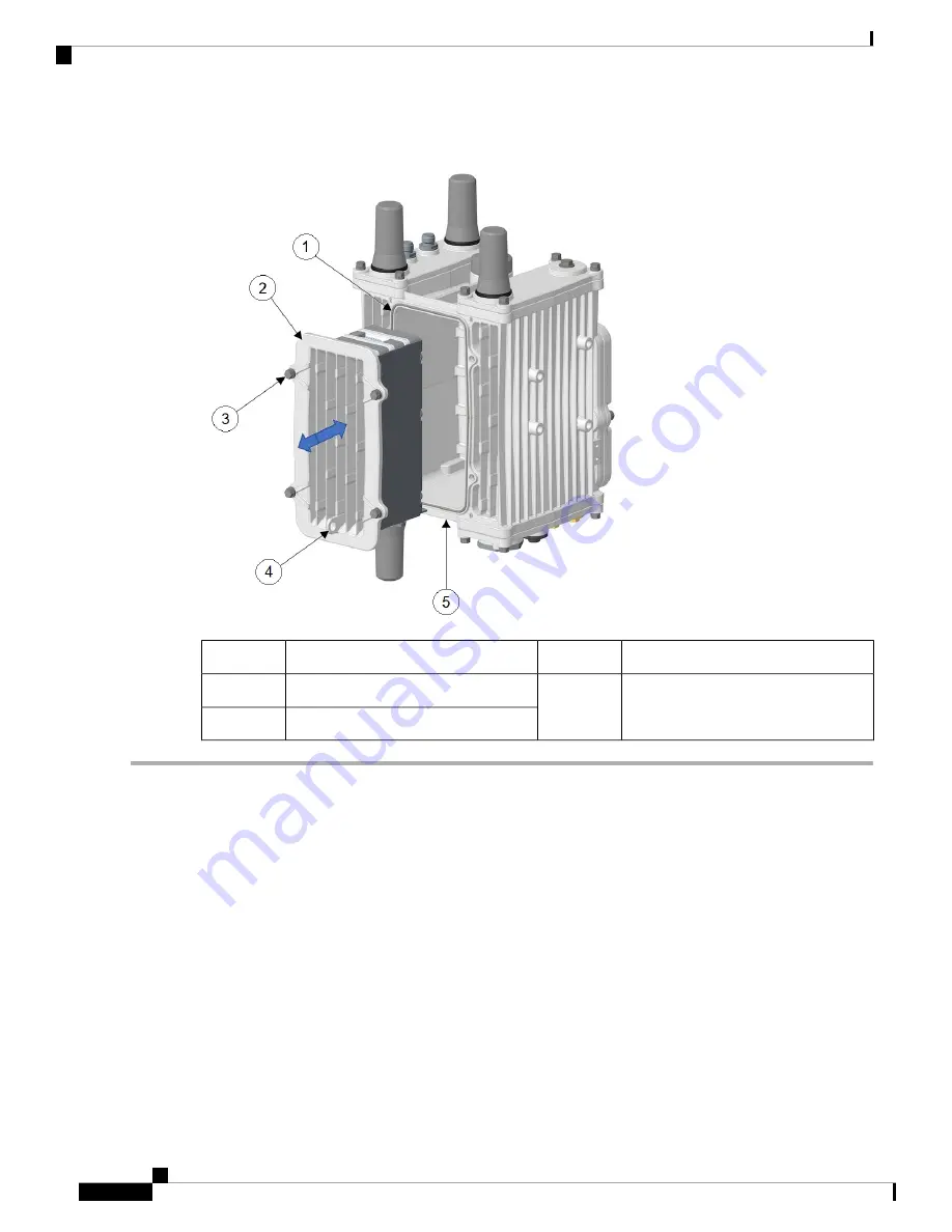
Figure 5: BBU Assembly or Blank Mounted on the Router

Padlock tab

4

BBU gasket

1

BBU security screw, in the bottom of
the router

5

BBU assembly/blank

2

M6 bolts (4)

3

Step 1

Ensure that BBU gasket is fully installed in the gasket groove and the sealing surface is clean.

Step 2

Ensure the BBU Security Screw is fully backed out (see

BBU Security Screw, on page 15

).

Step 3

Align the BBU assembly or blank with the router chassis, note the location of padlock tab.

Step 4

Carefully push the BBU assembly fully into cavity. BBU is self aligning with internal guide pins. Do not leave the BBU
assembly unattended until the M6 bolts have been tightened.

Step 5

Torque M6 bolts with 10mm socket driver. Torque to 15-20 in-lbs in the sequence shown below.

Installing Battery Backup Units

14

Installing Battery Backup Units

Installing BBU Assembly or Blank to the Router

Summary of Contents for Firepower 8140

Page 1: ...page 8 BBU Technical Specifications on page 16 Battery Backup Operations The battery backup unit BBU provides the router with an emergency power source if the AC power source is unavailable The router supports up to three BBU units installed at one time The units are mounted in the center front of the IR8140H When you install 3 BBUs up to 8 hours of battery backup power is available on a fully loa...

Page 2: ...until at least one of the following conditions is met All BBUs are completely discharged AC power to the router is restored The BBU is disabled with software commands see Cisco Catalyst IR8140 Heavy Duty Series Router Software Configuration For information on technical details about the router power path selection and the conditions that trigger the BBU to begin operating see BBU Technical Specifi...

Page 3: ...ff specific modules when the router switches to BBU power BBU Lifecycle Handling and Storage Guidelines This section contains information about the BBU status and condition during the BBU lifecycle and how to approach and manage it BBU Storage Related Definitions Shelf life Shelf life is the length of time before a BBU needs to be recharged in order to avoid BBU over discharge State of charge Stat...

Page 4: ...40H router is removed from service The router switches to DC power supplied by the BBU s and remains powered for approximately 8 hours After 8 hours the BBU s reaches low voltage disconnect and the remaining shelf life is a minimum of 21 days The BBU should be placed in BBU disable mode when the router is removed from service in order to extend BBU shelf life up to 365 21 days The remaining shelf ...

Page 5: ...returned for failure analysis BBUs removed for replacement must be disposed of in accordance with local guidelines US and Canadian customers should utilize www call2recycle org to properly recycle the lithium ion BBUs For local recycling outside of the US and Canada customers should contact the following Cisco email for guidance specific to customer s country region environment cisco com For furth...

Page 6: ...nsitive to electrostatic discharge ESD damage which can occur when electronic cards or components are handled improperly and can result in complete or intermittent failures To prevent ESD damage follow these guidelines Always use an ESD wrist or ankle strap and ensure that it makes good skin contact Connect the equipment end of the strap to an unfinished chassis surface Place the BBU on an antista...

Page 7: ...lug connector engages with the socket connector and the alignment pin with the alignment hole When you connect a second or third battery to a battery already installed use the alignment pin and hole to ensure correct battery position and align the battery connectors Figure 2 Rear of Battery Backup Unit Description Item BBU Alignment Pin 1 BBU Interface Plug 2 Captive screws 6 for installing the BB...

Page 8: ...ll immediately begin to power the router when it is connected Caution To prevent the BBU from powering the router prior to installation in the field the BBU is disabled during shipment To ensure the BBU can be charged and power the router when required enable the BBU right after installation When you replace a BBU in the router we highly recommend Note Replacing all the BBUs Verifying all the repl...

Page 9: ...bly or Blank From the Router on page 16 2 Removing the BBU Cage from the Faceplate on page 13 3 Removing BBU Modules from the BBU Cage on page 10 Installing BBU Modules to the BBU Cage Follow these steps to install BBU modules to the BBU cage BBU cage 4 Alignment hole 1 BBU security tab 5 Captive nuts 6 2 BBU cage pin notch 3 Installing Battery Backup Units 9 Installing Battery Backup Units Instal...

Page 10: ...ment pin with the BBU alignment hole and press the plug and socket connectors together Torque the six captive screws to 7 9 in lbs with a 1 Phillips screwdriver in sequence as shown in the following figure Removing BBU Modules from the BBU Cage To remove BBU modules from the BBU cage you must start with the last BBU module and work inward towards the back of the BBU cage Step 1 Loosen the 6 captiv...

Page 11: ...mbly to the faceplate as shown in the figure Note the location of BBU security tab in relation to the faceplate connector relief Step 2 Insert six M3 5 screws in the locations as shown in Torque screws to 10 12 in lbs in sequence as shown in the following figure Installing Battery Backup Units 11 Installing Battery Backup Units Attaching BBU Cage to the Faceplate ...

Page 12: ...Step 3 The BBU assembly is now ready to be mounted to the router Installing Battery Backup Units 12 Installing Battery Backup Units Attaching BBU Cage to the Faceplate ...

Page 13: ...crews that attach the BBU cage to the faceplate Do not discard the screws Step 2 Remove the BBU cage or assembly from the faceplate Installing BBU Assembly or Blank to the Router Follow these steps to install the BBU assembly or blank to the router Installing Battery Backup Units 13 Installing Battery Backup Units Removing the BBU Cage from the Faceplate ...

Page 14: ...see BBU Security Screw on page 15 Step 3 Align the BBU assembly or blank with the router chassis note the location of padlock tab Step 4 Carefully push the BBU assembly fully into cavity BBU is self aligning with internal guide pins Do not leave the BBU assembly unattended until the M6 bolts have been tightened Step 5 Torque M6 bolts with 10mm socket driver Torque to 15 20 in lbs in the sequence s...

Page 15: ...ted at the bottom of the router Follow these steps to install the BBU security screw Step 1 Ensure the BBU security screw is backed out until it hits retention plate Installing Battery Backup Units 15 Installing Battery Backup Units BBU Security Screw ...

Page 16: ...he router Step 1 Back out the BBU security screw until it hits retention plate See Figure 6 BBU Security Screw on page 16 Step 2 Loosen four M6 bolts with 10mm socket on the BBU faceplate do not remove the bolts from the faceplate Step 3 Pull the BBU assembly or blank out straight The BBU assembly is heavy Caution Step 4 Ensure the BBU gasket stays in place and the sealing surface is clean BBU Tec...

Page 17: ...wer restored in the range of 85V to 250V for more than 20 ms Remaining BBU capacity 5 External ambient temperature is outside the range of 40 to 122 F 40 to 50 C Exit discharge2 1 All conditions met 2 Any condition met and system is detected Charge Conditions Table 2 Battery Backup Unit Charging Specifications Description Charge Conditions No more than 20 W when charging Power draw State of Charge...

Page 18: ...ng 40 to 158 F 40 to 70 C 4 to 185 F 20 to 85 C Operation Idle Short term 14 to 113 F 10 to 45 C for 3 months maximum Long term 27 to 77 F 3 to 25 C 65 Relative Humidity 40 to 90 SOC 14 to 113 F 10 to 45 C for 3 months maximum Storage and shipping Battery Life Table 4 Battery Backup Unit Battery Life Charge Discharge Cycles Battery Life Product ID 500 5 years IRMH BATT 4AH Installing Battery Backu...

Reviews: