background image

2Jackscrew Installation Instructions (for EIP Ports)

Obtaining Technical Assistance

This document contains instructions for replacing the slide-type connector locks that
are standard on Cisco 7000 EIP ports with jackscrews so that you can connect cables
with thumbscrews to the ports. If you encounter problems that you are unable to
resolve, contact a customer service representative or the Technical Assistance Center
(TAC) for assistance. You can phone the TAC at 800 553-2447, or send email to

[email protected]

.

Before you call the TAC or a customer service representative, have the following
information ready:

Date you received the Cisco 7000

Chassis serial number (located on a label on the right rear deck of the chassis)

Type of software and version number

Type of installation or upgrade you are performing (replacing EIP cable locks)

Title and Doc. No. of this document (from the front page)

Brief description of the problem you are having

Brief explanation of the steps you have already taken to isolate and resolve the
problem

Maintenance agreement or warranty information

Refer to the Cisco 7000 Hardware Installation and Maintenance publication for
complete system installation and startup procedures, and for physical descriptions of
chassis components.

Product Overview

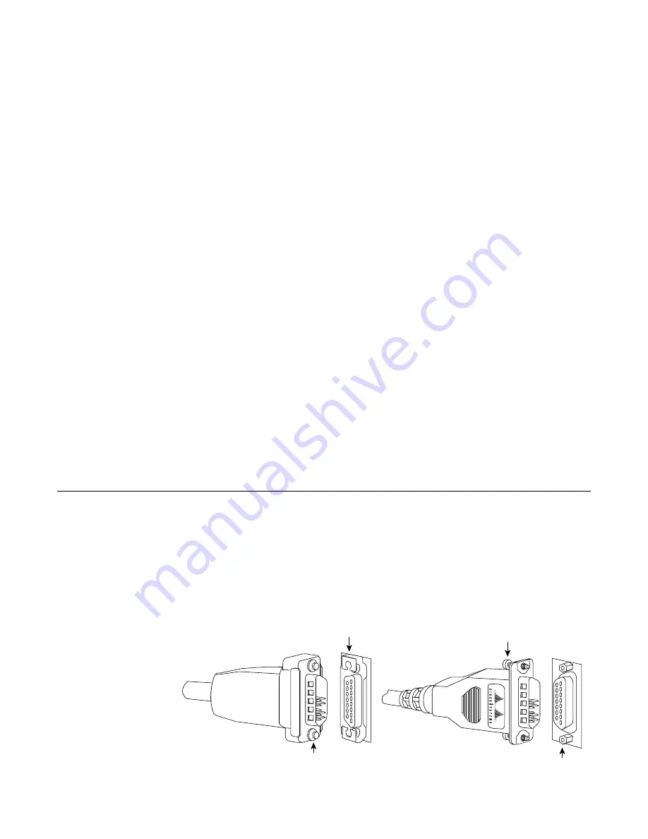
The type of connector lock you use on the EIP ports depends on the type of Ethernet
interface cables you use. Cables with two short posts on the cable connector need a port
with a slide-type lock—a bracket on the port slides (or snaps) around the posts on the
cable connector to secure it. Cables with knurled thumbscrews (screws you can tighten
with your fingers) on the cable connector need a port with jackscrews (into which you
insert and tighten the thumbscrews). Both types of locks are shown in Figure 1.

H1887

Sliding bracket

Post

Jackscrew

Thumbscrew

Summary of Contents for Ethernet Connectors Jackscrew

Page 1: ...s installed and operating in the chassis however we recommend that you shut down an enabled interfaces before you work on the port The sections in this document include the following Obtaining Technical Assistance page 2 If you encounter installation problems that you cannot resolve this section provides instructions for obtaining technical assistance and lists the information you will need to pro...

Page 2: ...acing EIP cable locks Title and Doc No of this document from the front page Brief description of the problem you are having Brief explanation of the steps you have already taken to isolate and resolve the problem Maintenance agreement or warranty information Refer to the Cisco 7000 Hardware Installation and Maintenance publication for complete system installation and startup procedures and for phy...

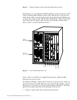
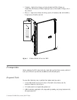
Page 3: ...change connector locks Figure 2 shows a 6 port EIP installed in IP slot 1 Figure 2 Cisco 7000 Chassis Rear View Figure 3 shows a 6 port EIP as it is shipped from the factory with the standard slide type locks on all six ports The Enabled LED lights to indicate that the EIP is receiving power and is enabled for operation The bank of 18 LEDs indicate the state of the individual interfaces with one h...

Page 4: ...uisites Before replacing the EIP connector locks ensure that you have the necessary parts and tools you will need to perform the installation without interruption Required Tools You need the following tools to perform this replacement procedure 1 8 inch flat blade screwdriver to remove the small screws that secure the slide lock bracket to the EIP port 3 16 inch nut driver to tighten the jackscrew...

Page 5: ...I shielding connectors and a handle are integral components of the carrier Although the metal carrier helps to protect the board from ESD you can still damage the board by touching the connector pins Always use a preventive antistatic strap whenever working on the EIP and avoid touching the connector pins Following are guidelines for preventing ESD damage Always use an ESD wrist strap or ankle str...

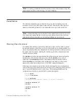
Page 6: ...nabled you can avoid potential problems by administratively shutting the interface down and when the replacement is complete enabling the interface again with commands you enter from the console terminal The shutdown interface subcommand disables all functions and prevents all packet transmission on the interface that you specify with the interface type slot port command The no shutdown interface ...

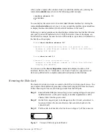
Page 7: ... text deleted Router show int eth 1 1 Ethernet1 1 is up line protocol is up Hardware is cxBus Ethernet address is 0000 0c bia 0c02 d0ce display text deleted You can also use the show configuration command to display the status of all interfaces Refer to the 9 17 Addendum to the Router Products Configuration and Reference publication for complete command descriptions and instructions Removing the S...

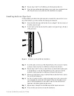
Page 8: ...llation Step 3 Insert the jackscrew into one of the threaded holes on the connector Turn the jackscrew clockwise about two full turns to thread it into the hole Step 4 Repeat steps 2 and 3 for the second jackscrew and lock washer placing the second jackscrew in the other threaded hole on the connector Turn the jackscrew clockwise about two full turns to thread it into the hole Step 5 Observe both ...

Page 9: ...if the interface responds with a different cable Step 6 Use show commands to display the state of the interfaces as follows Enter the command show int type slot port to display information about a specific interface port Enter the command show interfaces to display information about all interfaces Enter the command show configuration to check the configured state up or administratively down of all...

Page 10: ...scoWorks CxBus Netscape The Packet and SMARTnet trademarks and the Cisco logo is a registered trademark of Cisco Systems Inc All other products or services mentioned in this document are the trademarks service marks registered trademarks or registered service marks of their respective owners Copyright 1993 Cisco Systems Inc All rights reserved ...

Reviews: