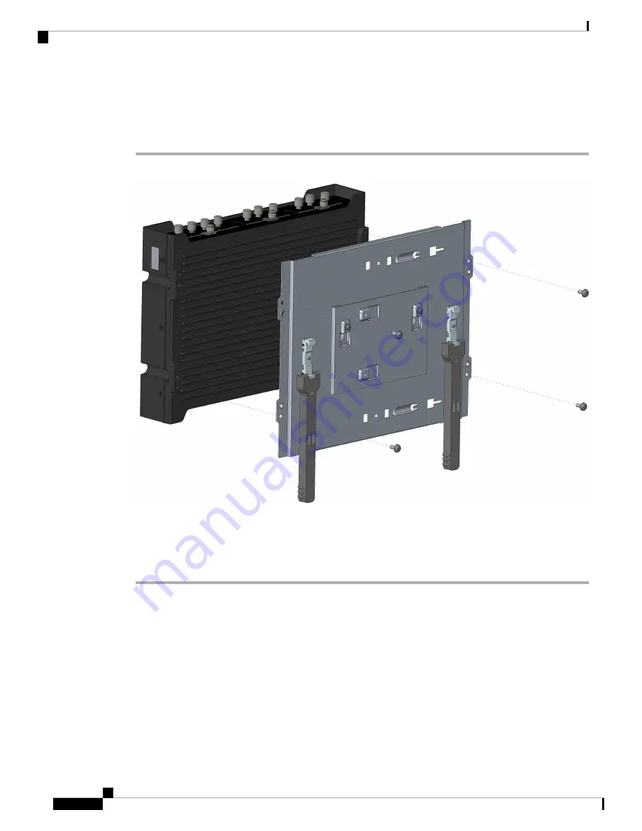
Mounting the DIN Rail Bracket on the Router (Horizontal)
Procedure
Step 1
Attach the DIN rail bracket to the back of the router, as shown in the following figure.
Step 2
Attach the DIN mounting bracket to the router using the four 8-32 screws provided in the kit. Position the
bracket over the four mounting holes and then insert the screws through the bracket into the chassis. Then
use 14 in. lbs. of torque to screw the bracket onto the router.
Step 3
After the bracket is attached to the router, it can be mounted onto the DIN rail.
Attaching the Bracket to the DIN Rail
To attach the Cisco IR1800 with the bracket to a DIN rail, see the following image and follow the steps
provided.
Cisco Catalyst IR1800 Rugged Series Router Hardware Installation Guide
28
Installing the Router
Mounting the DIN Rail Bracket on the Router (Horizontal)