background image

4.

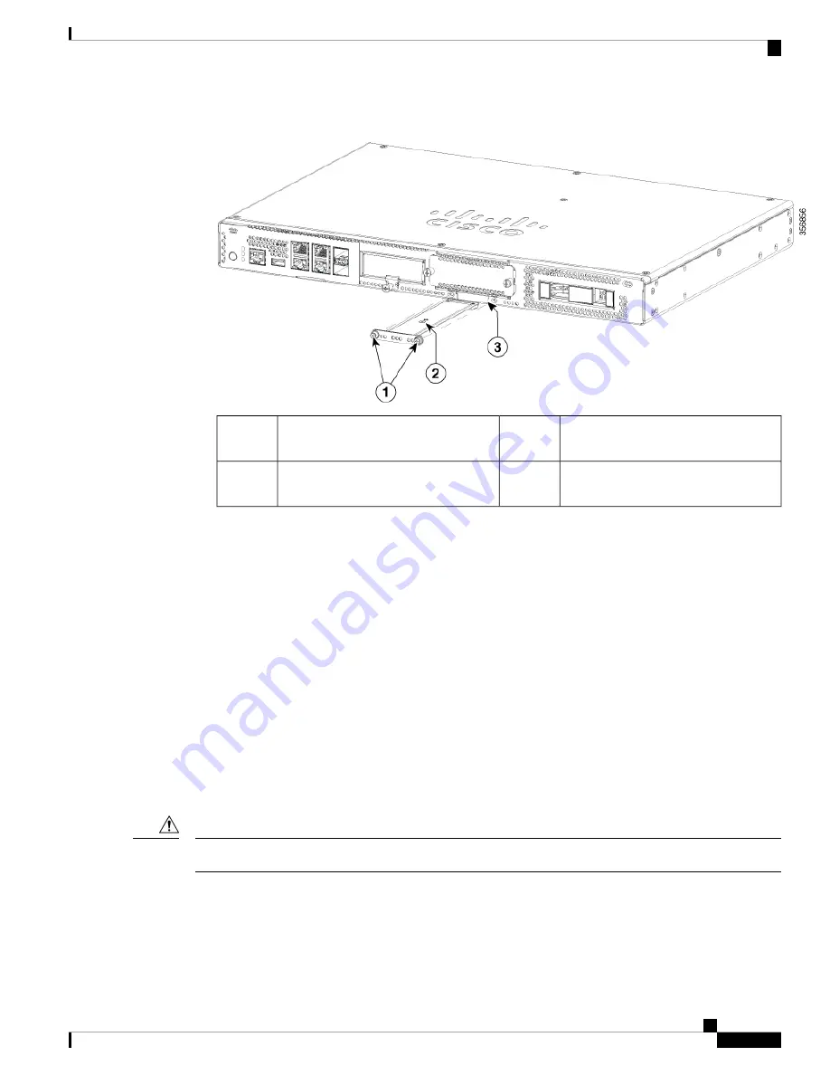
Plug in the new M.2 storage module in the same location and secure it with the screws.

M.2 module orientation with metal
carrier on top, M.2 module underneath.

2

Securing screws (torque 3.9-5.4 in-lbs)

1

Chassis cutout prevents M.2 installation
in wrong orientation.

3

Installing and Removing a NIM

These are the steps to install a NIM:

1.

Locate the NIM slot on the front panel.

2.

Loosen the screws to remove NIM blank cover.

3.

Insert the NIM into the slot.

4.

Tighten the screws to secure the NIM in the slot.

These are the steps to remove a NIM:

1.

If the NIM is up and running, issue the following command to shut down the NIM gracefully before
removing it:

hw-module subslot slot 0/2 stop

If you do not shut down the NIM gracefully before removing it, the NIM card could get damaged.

Caution

2.

Locate the NIM slot on the front panel.

3.

Loosen the screws that secure the NIM.

4.

Gently pull out the NIM from the slot.

Installing and Upgrading Field Replaceable Units

7

Installing and Upgrading Field Replaceable Units

Installing and Removing a NIM

Summary of Contents for Catalyst 8200 Series

Page 1: ...Keep the optical transmit and receive ports covered whenever a cable is not connected to the port Invisible laser radiation may be emitted from disconnected fibers or connectors Do not stare into beams or view directly with optical instruments Statement 1051 Warning Ultimate disposal of this product should be handled according to all national laws and regulations Statement 1040 Warning Pluggable o...

Page 2: ...ection and disconnect the power supply before you perform any module replacement Step 2 Disconnect all cables from the SFP Invisible laser radiation may be emitted from disconnected fibers or connectors Do not stare into beams or view directly with optical instruments Statement 1051 Warning The latching mechanism used on many SFPs locks the SFP into place when cables are connected Do not pull on t...

Page 3: ... trained and qualified personnel should be allowed to install replace or service this equipment Statement 1030 Warning These are the steps to remove the chassis cover 1 Confirm that the chassis is turned off and disconnected from the power supply or power supplies 2 Place the chassis on a flat surface 3 Remove the screws at top of the chassis cover 4 Remove one screw from each side of the device a...

Page 4: ...device and use the screws to secure it to the device Note Installing a DIMM There are two DDR4 DIMM slots DIMMs have a polarization notch on the connecting edge to prevent incorrect insertion Figure 4 DIMM Showing Polarization Notch Polarization Notch 1 Installing and Upgrading Field Replaceable Units 4 Installing and Upgrading Field Replaceable Units Installing a DIMM ...

Page 5: ... up with the polarization key on the connector 5 Insert the DIMM into the connector 6 Replace the chassis cover Removing a DIMM These are the steps to remove a DIMM 1 Remove the chassis cover 2 Locate the DIMM module on the device Refer to the Chassis Internal section to identify and locate the DIMM module 3 Pull the latches away from the DIMM at both ends to lift the DIMM slightly Pull the DIMM o...

Page 6: ...ed These are the steps to upgrade the M 2 storage module 1 Power off of the system before replacing M 2 2 Locate the M 2 storage module slot Refer to Chassis Front Panel to identify and locate the module Figure 6 Blank M 2 Slot M 2 slot blank cover 1 3 Loosen the screws that secures the M 2 blank cover or existing M 2 module in the slot Installing and Upgrading Field Replaceable Units 6 Installing...

Page 7: ...over 3 Insert the NIM into the slot 4 Tighten the screws to secure the NIM in the slot These are the steps to remove a NIM 1 If the NIM is up and running issue the following command to shut down the NIM gracefully before removing it hw module subslot slot 0 2 stop If you do not shut down the NIM gracefully before removing it the NIM card could get damaged Caution 2 Locate the NIM slot on the front...

Page 8: ...ves the drive bay slot is closed with a blank cover These are the steps to install a drive in a drive bay 1 The drive bay is in the front panel of the device The bay is closed with a cover if there are no drives in the slots 2 Press the push button on the center of the cover and pull the cover out of the system to expose the slot 3 Slide the drive into the slot Keep the drive bays covered when the...

Reviews: