Chapter 3 Switch Installation
Preparing for Installation
3-12
Catalyst 3560 Switch Hardware Installation Guide
78-16057-01
Step 2
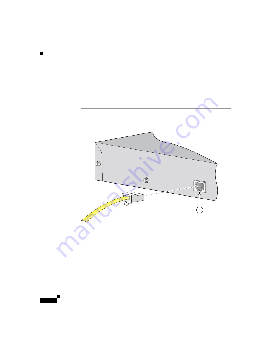
Using the supplied RJ-45-to-DB-9 adapter cable, insert the RJ-45 connector into
the console port, as shown in
Step 3
Attach the DB-9 female DTE adapter of the RJ-45-to-DB-9 adapter cable to a PC,
or attach an appropriate adapter to the terminal.
Step 4
Start the terminal-emulation program if you are using a PC or terminal.
Figure 3-1
Connecting to the Console Port
Powering On the Switch and Running POST
If your configuration has an RPS, connect the switch and the RPS to the same AC
power source. See the
“Power Connectors” section on page 2-13
, and refer to the
Cisco RPS documentation for more information.
1
Console port
CONSOLE
97915
1
Summary of Contents for Catalyst 3560
Page 6: ......
Page 12: ...Contents x Catalyst 3560 Switch Hardware Installation Guide 78 16057 01 ...
Page 23: ...xxi Catalyst 3560 Switch Hardware Installation Guide 78 16057 01 Preface Conventions ...
Page 24: ...Preface Conventions xxii Catalyst 3560 Switch Hardware Installation Guide 78 16057 01 ...
Page 25: ...xxiii Catalyst 3560 Switch Hardware Installation Guide 78 16057 01 Preface Conventions ...


