background image

17

Securing the Switch on a Desk or Shelf (only the Catalyst 3560-8PC
Switch)

Note

This section is specific to the Catalyst 3560-8PC switch. For installation information for other
Catalyst 3560 switches, see “Rack-Mounting the Switch (All Catalyst 3560 Switches Except
the Catalyst 3560-8PC Switch)” section on page 14.

To place the switch on a desk without using the mounting screws, simply attach the four rubber feet
on the bottom panel of the switch.

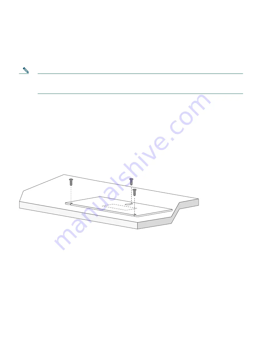
To secure the switch on top of or under a desk or a shelf, or on a wall, use the mounting template and
three mounting screws. Follow these steps:

1.

Position the screw template on the mounting surface with the two side-by-side slots forward. Peel
the adhesive strip off the bottom, and attach the template.

2.

Use a 0.144-inch (3.7 mm) or a #27 drill bit to drill a 1/2-inch (12.7 mm) hole in the three template
screw slot positions.

3.

Insert the screws in the slots on the template, and tighten until they touch the template. Remove
the template from the mounting surface.

Number-8 Phillips pan-head screws

Mounting template

Summary of Contents for Catalyst 3560

Page 1: ...ng the Switch 5 Installing the Switch 6 Connecting to the Switch Ports 7 In Case of Difficulty 8 Obtaining Documentation 9 Documentation Feedback 10 Cisco Product Security Overview 11 Product Alerts and Field Notices 12 Obtaining Technical Assistance 13 Obtaining Additional Publications and Information 14 Cisco Limited Lifetime Hardware Warranty Terms ...

Page 2: ...ch rear panel You can order printed copies of the manuals from the Cisco com sites and from the telephone numbers listed in the Obtaining Documentation section on page 26 For translations of the warnings that appear in this publication see the Regulatory Compliance and Safety Information for the Catalyst 3560 Switch that accompanies this guide 2 Taking Out What You Need Follow these steps 1 Unpack...

Page 3: ...ole cable Two 19 inch mounting brackets Four number 12 Phillips machine screws Four number 8 Phillips truss head screws Six number 8 Phillips flat head screws Four rubber mounting feet AC power cord Connector cover for redundant power system RPS Two number 4 pan head screws Cable guide One black Phillips machine screw Documentation Catalyst 3560G SERIES PoE 48 SYST RPS STAT DUPLX SPEED PoE MODE 1 ...

Page 4: ... r t h e C a t a l y s t 3 5 6 0 S w i t c h C a t a l y s t 3 5 6 0 S w i t c h G e t t i n g S t a r t e d G u i d e C i s c o P r o d u c t O w n e r s h i p R e g i s t r a t i o n c a r d Console cable Four rubber mounting feet AC power cord AC powered switches only Screw template Mounting magnet Documentation Catalyst 3560SERIES PoE 8 PoE SPD DPLX STAT SYST MODE 1 CONSOLE 1x 2x 3x 4x 5x 6x 7...

Page 5: ...properly Wait for the switch to complete POST which can take several minutes Step 4 Verify that POST has completed by confirming that the SYST LED remains green If the switch fails POST the SYST LED turns amber POST errors are usually fatal Contact your Cisco technical support representative if your switch fails POST Step 5 Press and hold the Mode button for 3 seconds When all of the LEDs left of ...

Page 6: ...a web browser on your PC Enter the IP address 10 0 0 1 in the web browser and press Enter The Express Setup page appears If it does not appear see the In Case of Difficulty section on page 23 for help DHCP enabled PC Catalyst 3560G SERIES PoE 48 SYST RPS STAT DUPLX SPEED PoE MODE 1 2 5 6 7 8 9 10 11 12 13 14 15 16 3 4 1X 2X 15X 16X 17 18 21 22 23 24 25 26 27 28 29 30 31 32 19 20 17X 18X 31X 32X 33...

Page 7: ...5 alphanumeric characters can start with a number is case sensitive allows embedded spaces but does not allow spaces at the beginning or end In the Confirm Switch Password field enter your password again Step 11 Optional You can enter the Optional Settings information now or enter it later by using the device manager interface In the Host Name field enter a name for the switch The host name is lim...

Page 8: ...ess SNMP information but you cannot modify it When you set the SNMP write community you can both access and modify SNMP information In the System Contact and System Location fields enter a contact name and the wiring closet floor or building where the switch is located Step 14 Optional You can enable Internet Protocol version 6 IPv6 on the switch From the Advanced Settings tab check the Enable IPv...

Page 9: ...gh a web browser Follow these steps 1 Start a web browser on your PC or workstation 2 Enter the switch IP address in the web browser and press Enter The device manager page appears 3 Use the device manager to perform basic switch configuration and monitoring Refer to the device manager online help for more information 4 For more advanced configuration install Cisco Network Assistant as described i...

Page 10: ...e console port on the switch 2 Start a terminal emulation program on the PC 3 Configure the PC terminal emulation software for 9600 baud 8 data bits no parity 1 stop bit and no flow control 4 Use the CLI to enter commands to configure the switch See the software configuration guide and the command reference for more information Other Management Options You can use SNMP management applications such...

Page 11: ...install the switch verify that these guidelines are met Airflow around the switch and through the vents is unrestricted Note We strongly recommend that you allow at least 3 inches 7 6 cm of clearance around the ventilation openings Temperature around the switch does not exceed 113 F 45 C Humidity around the switch does not exceed 85 percent Altitude at the installation site is not greater than 10 ...

Page 12: ...airflow restriction and overheating Do not stack switches or place Catalyst 3560 8PC switches side by side unless they are separated all around by at least 3 inches 7 6 cm of clearance from each other Do not wall mount the Catalyst 3560 8PC switch with its front panel facing up or to the side We recommend wall mounting the switch with its front panel facing down to prevent airflow restriction and ...

Page 13: ...oduct Statement 1008 Warning To prevent bodily injury when mounting or servicing this unit in a rack you must take special precautions to ensure that the system remains stable The following guidelines are provided to ensure your safety This unit should be mounted at the bottom of the rack if it is the only unit in the rack When mounting this unit in a partially filled rack load the rack from the b...

Page 14: ...aware of the hazard A restricted access area can be accessed only through the use of a special tool lock and key or other means of security Statement 1072 Rack Mounting the Switch All Catalyst 3560 Switches Except the Catalyst 3560 8PC Switch Note This section applies to all Catalyst 3560 switches except the Catalyst 3560 8PC switch For installation information for the Catalyst 3560 8PC switch see...

Page 15: ...7X 18X 31X 32X 33 34 37 38 39 40 41 42 43 44 45 46 47 48 35 36 33X 34X 47X 48X 49 50 51 52 Catalyst 3560G SERIES PoE 48 SYST RPS STAT DUPLX SPEED PoE MODE 1 2 5 6 7 8 9 10 11 12 13 14 15 16 3 4 1X 2X 15X 16X 17 18 21 22 23 24 25 26 27 28 29 30 31 32 19 20 17X 18X 31X 32X 33 34 37 38 39 40 41 42 43 44 45 46 47 48 35 36 33X 34X 47X 48X 49 50 51 52 CONSOLE DC INPUTS FOR REMOTE POWER SUPPLY SPECIFIED ...

Page 16: ...0 17X 18X 31X 32X 33 34 37 38 39 40 41 42 43 44 45 46 47 48 35 36 33X 34X 47X 48X 49 50 51 52 Catalyst 3560G SERIES PoE 48 SYST RPS STAT DUPLX SPEED PoE MODE 1 2 5 6 7 8 9 10 11 12 13 14 15 16 3 4 1X 2X 15X 16X 17 18 21 22 23 24 25 26 27 28 29 30 31 32 19 20 17X 18X 31X 32X 33 34 37 38 39 40 41 42 43 44 45 46 47 48 35 36 33X 34X 47X 48X 49 50 51 52 CONSOLE DC INPUTS FOR REMOTE POWER SUPPLY SPECIFI...

Page 17: ...anel of the switch To secure the switch on top of or under a desk or a shelf or on a wall use the mounting template and three mounting screws Follow these steps 1 Position the screw template on the mounting surface with the two side by side slots forward Peel the adhesive strip off the bottom and attach the template 2 Use a 0 144 inch 3 7 mm or a 27 drill bit to drill a 1 2 inch 12 7 mm hole in th...

Page 18: ...18 4 Place the switch onto the mounting screws and slide it forward until it locks in place 1 CONSOLE 1x 2x 3x 4x 5x 6x 7x 8x Catalyst 3560SERIES PoE 8 PoE SPD DPLX STAT SYST MODE ...

Page 19: ...hes see Rack Mounting the Switch All Catalyst 3560 Switches Except the Catalyst 3560 8PC Switch section on page 14 Follow these steps 1 Position the mounting magnet on the mounting surface 2 Place the bottom of the switch on the mounting magnet C at al ys t 35 60 SE RIE S Po E 8 SYS T STA T DPL X SPD SYS T CO NS OL E 1x 2x 3x 4x 5x 6x 7x 8x 1 Metal mounting surface Mounting magnet Switch bottom pa...

Page 20: ...es power when a valid powered device is connected to it For information about configuring and monitoring PoE ports see the switch software configuration guide For information about troubleshooting PoE problems see the Catalyst 3560 Switch Hardware Installation Guide on Cisco com Note For simplified cabling the automatic medium dependent interface crossover auto MDIX feature is enabled by default o...

Page 21: ...essary Step 1 Grasp the module on the sides and insert it into the switch slot until you feel the connector snap into place Step 2 Insert an appropriate cable into the module port Note If your switch has a dual purpose port see the Connecting to a Dual Purpose Port section on page 22 for additional considerations Step 3 Insert the other cable end into the other device 2 2 1 1 Catalyst 3560G SERIES...

Page 22: ...e LED is off the target device might not be turned on there might be a cable problem or there might be a problem with the adapter installed in the target device See the In Case of Difficulty section on page 23 for information about online assistance Step 1 Insert either an RJ 45 connector to the 10 100 1000 port or install an SFP module into the SFP module slot and connect a cable to the SFP modul...

Page 23: ...ss the Mode button to enter Express Setup mode Did you try to continue without confirming that the switch was in Express Setup mode Verify that all LEDs left of the Mode button are green On some models the RPS LED is off If necessary press the Mode button to enter Express Setup mode Does your PC have a static IP address If yes change your PC settings to temporarily use DHCP before connecting to th...

Page 24: ...witch reboots The switch now behaves like an unconfigured switch You can enter the switch IP information by using Express Setup as described in the Running Express Setup section on page 5 Accessing Help Online First look for a solution to your problem in the troubleshooting section of the Catalyst 3560 Hardware Installation Guide or the Catalyst 3560 Software Configuration Guide on Cisco com You c...

Page 25: ...ailable on Cisco com This guide provides complete hardware descriptions and detailed installation procedures Regulatory Compliance and Safety Information for the Catalyst 3560 Switch order number DOC 7816665 This guide contains agency approvals compliance information and translated warning statements Catalyst 3560 Switch Software Configuration Guide order number DOC 7816156 This guide provides a p...

Page 26: ...hardware and software products With the DVD you have access to the HTML documentation and some of the PDF files found on the Cisco website at this URL http www cisco com univercd home home htm The Product Documentation DVD is created and released regularly DVDs are available singly or by subscription Registered Cisco com users can order a Product Documentation DVD product number DOC DOCDVD or DOC ...

Page 27: ...at this URL http www cisco com go psirt To see security advisories security notices and security responses as they are updated in real time you can subscribe to the Product Security Incident Response Team Really Simple Syndication PSIRT RSS feed Information about how to subscribe to the PSIRT RSS feed is found at this URL http www cisco com en US products products_psirt_rss_feed html Reporting Sec...

Page 28: ... Field Notices Modifications to or updates about Cisco products are announced in Cisco Product Alerts and Cisco Field Notices You can receive Cisco Product Alerts and Cisco Field Notices by using the Product Alert Tool on Cisco com This tool enables you to create a profile and choose those products for which you want to receive information To access the Product Alert Tool you must be a registered ...

Page 29: ... All Tools A Z tab and then choosing Cisco Product Identification Tool from the alphabetical list This tool offers three search options by product ID or model name by tree view or for certain products by copying and pasting show command output Search results show an illustration of your product with the serial number label location highlighted Locate the serial number label on your product and rec...

Page 30: ...11 Australia 1 800 805 227 EMEA 32 2 704 55 55 USA 1 800 553 2447 For a complete list of Cisco TAC contacts go to this URL http www cisco com techsupport contacts Definitions of Service Request Severity To ensure that all service requests are reported in a standard format Cisco has established severity definitions Severity 1 S1 An existing network is down or there is a critical impact to your busi...

Page 31: ...ides a variety of Cisco books reference guides documentation and logo merchandise Visit Cisco Marketplace the company store at this URL http www cisco com go marketplace Cisco Press publishes a wide range of general networking training and certification titles Both new and experienced users will benefit from these publications For current Cisco Press titles and other information go to Cisco Press ...

Page 32: ...teps to access and download the Cisco Information Packet and your warranty and license agreements from Cisco com 1 Start your browser and go to this URL http www cisco com univercd cc td doc es_inpck cetrans htm The Warranties and License Agreements page appears 2 To read the Cisco Information Packet follow these steps a Click the Information Packet Number field and make sure that the part number ...

Page 33: ...om the announcement of the discontinuance Replacement Repair or Refund Policy for Hardware Cisco or its service center will use commercially reasonable efforts to ship a replacement part within ten 10 working days after receipt of the Return Materials Authorization RMA request Actual delivery times can vary depending on the customer location Cisco reserves the right to refund the purchase price as...

Page 34: ...34 ...

Page 35: ...35 ...

Page 36: ... Slovenia South Africa Spain Sweden Switzerland Taiwan Thailand Turkey Ukraine United Kingdom United States Venezuela Vietnam Zimbabwe 2004 2006 Cisco Systems Inc All rights reserved Printed in the USA on recycled paper containing 10 postconsumer waste 78 16660 04 DOC 7816660 CCVP the Cisco Logo and the Cisco Square Bridge logo are trademarks of Cisco Systems Inc Changing the Way We Work Live Play...

Reviews: