background image

Alarm port

11

Power Supply 1 LED (AC or
DC)

4

USB Console port

12

Console port (TIA/EIA-232F)

5

Board power LED

13

Management port

6

System Status LED

14

Auxiliary Console port

7

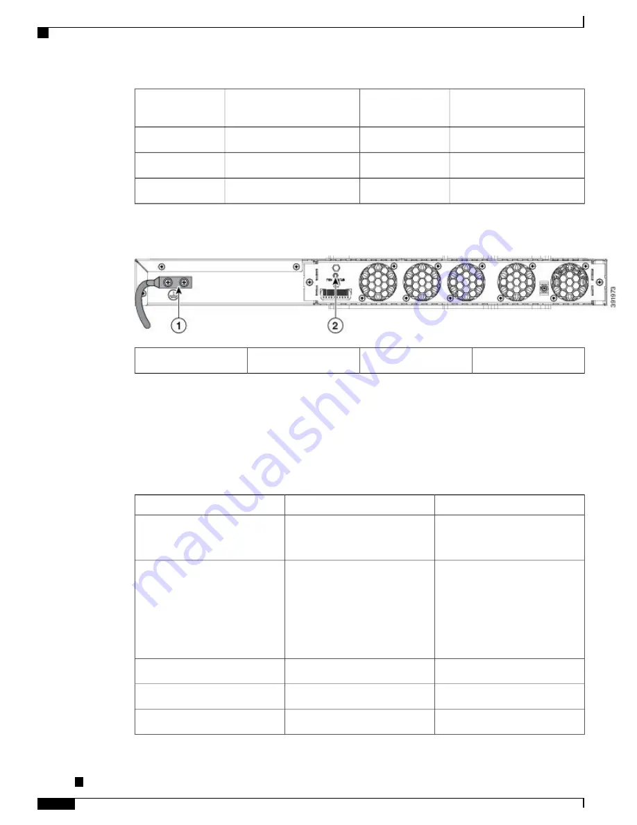
Figure 9: Back Panel of Cisco ASR-920-24SZ-M, ASR-920-24TZ-M Router

Fan status LED

2

Grounding lugs

1

Specifications

The table below describes the other features of Cisco ASR-920-24SZ-IM Router (AC and DC) and Cisco
ASR-920-24SZ-M, ASR-920-24TZ-M Router (AC and DC) Routers.

Table 3: Cisco ASR 920-24SZ-IM, ASR-920-24SZ-M, ASR-920-24TZ-M Router Specifications

ASR-920-24SZ-M, ASR-920-24TZ-M

ASR-920-24SZ-IM

Specification

17.5 x 9.43 x 1.72 inches

Dimensions exclude the
PSU and IM handle.

Note

17.5 x 9.43 x 2.6 inches

Dimensions exclude the
PSU and IM handle.

Note

DimensionWidth x Depth x Height

ASR-920-24SZ-M: 5.53 kg

ASR-920-24TZ-M: 4.90 kg

(inclusive of rack brackets,
twenty-four SFP (only for
ASR-920-24SZ-M) and four SFP+
optics and two AC PSUs)

7.08 kg

(inclusive of rack brackets,
twenty-four SFP and four SFP+
optics, two AC PSUs and an IM
card)

Weight

One RU

One and a half RU

Rack Unit

Front to back

Front to back and side to back

Airflow

Front cable access

Front cable access

Cable access

   Cisco ASR-920-24SZ-IM, ASR-920-24SZ-M, ASR-920-24TZ-M Aggregation Services Router Hardware Installation

Guide

12

Overview

Specifications

Summary of Contents for ASR-920-24SZ-IM

Page 1: ...regation Services Router Hardware Installation Guide First Published 2016 07 04 Americas Headquarters Cisco Systems Inc 170 West Tasman Drive San Jose CA 95134 1706 USA http www cisco com Tel 408 526 4000 800 553 NETS 6387 Fax 408 527 0883 Text Part Number ...

Page 2: ... Cisco Systems Inc All rights reserved ...

Page 3: ...le A900 IMA8T 3 10 Gigabit Ethernet XFP Interface Module A900 IMA1X 4 2x1 10 Gigabit Ethernet SFP Interface Module A900 IMA2Z 5 8 Port 1 Gigabit Ethernet 1 Port 10 Gigabit Ethernet SFP Combination Interface Module 6 8 Port T1 E1 Interface Module A900 IMA8D 7 Interface Availability on Interface Modules 7 Front and Back Panel 9 Specifications 12 External Interfaces 14 Network Interfaces 14 Network T...

Page 4: ...ons for Module Installation and Removal 27 Safety with Electricity 27 Power Supply Considerations 30 Preventing ESD Damage 30 Site Planning 31 General Precautions 31 Site Planning Checklist 31 Site Selection Guidelines 32 Environmental Requirements 32 Physical Characteristics 33 Air Flow Guidelines 33 Air Flow Guidelines for ETSI Rack Installation 36 Floor Loading Considerations 36 Site Power Guid...

Page 5: ...g the Router 49 Prerequisites 49 Installing the Router in a Rack 50 Installing the Chassis Brackets 50 Installing the Router Chassis in the Rack 56 Attaching the Cable Guides 59 Wall Mounting the Routers 61 Attaching the Brackets to the Router for Wall Mounting 62 Mounting Routers on the Wall 62 Installing and Removing the Interface Module 66 Installing the Interface Module 66 Removing the Interfa...

Page 6: ...SFP Modules 97 Installing the Chassis Ground Connection 98 Power Connection Guidelines 100 Guidelines for DC Powered Systems 101 Guidelines for AC Powered Systems 101 Preventing Power Loss 101 Activating a DC Power Supply 102 Activating an AC Power Supply 102 Connecting a Router to the Network 103 Connecting Console Cables 103 Connecting to the USB Serial Port Using Microsoft Windows 103 Connectin...

Page 7: ...r 118 Verifying the Front Panel LEDs 121 Verifying the Hardware Configuration 121 Checking Hardware and Software Compatibility 122 Configuring the Router at Startup 122 Accessing the CLI Using the Console 122 Configuring Global Parameters 124 Checking the Running Configuration Settings 125 Saving the Running Configuration to NVRAM 125 Safely Powering Off the Router 125 Automatic Shutdown of the Ro...

Page 8: ... Fiber Specifications 132 Alarm Conditions 132 C H A P T E R 6 Site Log 133 C H A P T E R 7 Supported PIDs 135 Cisco ASR 920 24SZ IM ASR 920 24SZ M ASR 920 24TZ M Aggregation Services Router Hardware Installation Guide viii Contents ...

Page 9: ...920 24SZ M Twenty Four 1GE Fiber ports and Four 10G ports with replaceable redundant AC and DC power supplies ASR 920 24TZ M Twenty Four 1 GE Copper ports and Four 10G ports with replaceable redundant AC and DC power supplies Document Revision History page ix Document Audience page x Document Organization page x Document Conventions page x Obtaining Documentation and Submitting a Service Request p...

Page 10: ...r Installation on page 25 Describes the installation of router on a rack as well as installation of its components Installing the Router on page 49 Describes basic router configuration Initial Configuration on page 117 Describes troubleshooting information Troubleshooting on page 127 Provides a record of actions related to installing and maintaining the router Site Log on page 133 Describes the su...

Page 11: ...tes a comment line Means reader take note Notes contain helpful suggestions or references to material not covered in the manual Note Means the following information will help you solve a problem The tips information might not be troubleshooting or even an action but could be useful information similar to a Timesaver Tip Means reader be careful In this situation you might perform an action that cou...

Page 12: ...latory and customer requirements Warning Obtaining Documentation and Submitting a Service Request For information on obtaining documentation submitting a service request and gathering additional information see the monthly What s New in Cisco Product Documentation which also lists all new and revised Cisco technical documentation Subscribe to the What s New in Cisco Product Documentation which lis...

Page 13: ...four 10GE and twenty four 1GE Fiber one slot for modular interface card and redundant modular power supplies AC DC The interface modules from ASR 900 family of routers can be leveraged for use with this model ASR 920 Fixed ASR 920 24SZ M ASR 920 24TZ M This sub family with 1 RU form factor has fixed ENET interfaces four 10GE and twenty four 1GE Copper or SFP and redundant modular power supplies AC...

Page 14: ...e X SFP modules Copper SFP modules Digital optical monitoring as specified by the SFP Any mix of SFPs is supported unless specifically noted Pause flow control as defined by the 802 3x standard Frame size of 9216 bytes Synchronous ENET operation that provides its recovered receive clock as an input clock source for the SETS as well as uses the system wide reference clock to derive its transmit clo...

Page 15: ...gabit Ethernet copper ports The figure below shows the interface module Figure 1 8 x 1 Gigabit Ethernet RJ45 Copper Interface Module For more information about installing an RJ45 Gigabit Ethernet module see the Installing the Interface Module section To determine interfaces available on the RJ45 Gigabit Ethernet module see the Interface Availability on Interface Modules section Cisco ASR 920 24SZ ...

Page 16: ...e Installing the Interface Module section To determine interfaces available on the 10 Gigabit Ethernet XFP module see the Interface Availability on Interface Modules section For information on supported SFPs see the Cisco ASR 900 Series Aggregation Services Router Interface Modules Data Sheet at http www cisco com c en us products routers asr 903 series aggregation services routers datasheet listi...

Page 17: ...terface Module section To determine interfaces available on the 2X10 GE SFP Gigabit Ethernet module see the Interface Availability on Interface Modules section For information on supported SFPs see the Cisco ASR 900 Series Aggregation Services Router Interface Modules Data Sheet at http www cisco com c en us products routers asr 903 series aggregation services routers datasheet listing html Cisco ...

Page 18: ... Gigabit Ethernet interface module is a high density combination interface module This module supports 8 Gigabit Ethernet Copper ports and 1 10 Gigabit Ethernet SFP port Figure 4 8 port 1 GE RJ45 1 port 10 GE SFP Interface Module Cisco ASR 920 24SZ IM ASR 920 24SZ M ASR 920 24TZ M Aggregation Services Router Hardware Installation Guide 6 Overview Interface Modules ...

Page 19: ... on the 8 Port T1 E1 interface module see the 8 T1 E1 Interface Module LEDs section For RJ45C pinout information on the 8 Port T1 E1 interface module see the RJ45C Port Pinouts section Interface Availability on Interface Modules Cisco ASR 920 24SZ IM Router does not support over subscription mode You must disable the ports as appropriate to restrict the system usage to 64 Gbps Enabling all the int...

Page 20: ...tity Interface Module DS3 E3 OC3 OC12 T1 E1 10GE SFP Cu 0 0 0 4 24 0 0 None 16 to 23 No 0 0 0 4 16 8 1 A900 IMA8T Yes 0 0 0 6 24 0 1 A900 IMA2Z Yes 0 0 0 5 24 0 1 A900 IMA1X 20 to 23 No 0 0 8 4 20 0 1 A900 IMA8D Cisco ASR 920 24SZ IM ASR 920 24SZ M ASR 920 24TZ M Aggregation Services Router Hardware Installation Guide 8 Overview Interface Modules ...

Page 21: ...24SZ IM Router Figure 6 Front Panel of Cisco ASR 920 24SZ IM Router 4x10GE SFP 12 Power Supply 0 AC or DC 1 Alarm port 13 Power Supply 0 LED AC or DC 2 Cisco ASR 920 24SZ IM ASR 920 24SZ M ASR 920 24TZ M Aggregation Services Router Hardware Installation Guide 9 Overview Front and Back Panel ...

Page 22: ... 18 Console port TIA EIA 232F 7 IM Status LED 19 Auxiliary Console port 8 System Status LED 20 Management port 9 Board power LED 21 24x1GE SFP Fiber ports 10 Slot for ports on the interface module 11 Figure 7 Back Panel of Cisco ASR 920 24SZ IM Router Fan status LED 2 Grounding lugs 1 Cisco ASR 920 24SZ IM ASR 920 24SZ M ASR 920 24TZ M Aggregation Services Router Hardware Installation Guide 10 Ove...

Page 23: ...4SZ M 24x1GE SFP Copper Cisco ASR 920 24TZ M 8 Power Supply 0 AC or DC 1 4x10GE SFP 9 Power Supply 0 LED AC or DC 2 USB Memory port 10 Power Supply 1 AC or DC 3 Cisco ASR 920 24SZ IM ASR 920 24SZ M ASR 920 24TZ M Aggregation Services Router Hardware Installation Guide 11 Overview Front and Back Panel ...

Page 24: ... 920 24TZ M ASR 920 24SZ IM Specification 17 5 x 9 43 x 1 72 inches Dimensions exclude the PSU and IM handle Note 17 5 x 9 43 x 2 6 inches Dimensions exclude the PSU and IM handle Note DimensionWidth x Depth x Height ASR 920 24SZ M 5 53 kg ASR 920 24TZ M 4 90 kg inclusive of rack brackets twenty four SFP only for ASR 920 24SZ M and four SFP optics and two AC PSUs 7 08 kg inclusive of rack brackets...

Page 25: ... 24SZ M 494 76 BTU hr Maximum 375 33 BTU hr Typical ASR 920 24TZ M Max 443 57 BTU hr Maximum 341 21 BTU hr Typical 614 18 BTU hr Maximum 443 57 BTU hr Typical including installed IM Power Dissipation 40º C to 70º C 5 95 RH 40º C to 70º C 5 95 RH Operating Temperature Humidity 4 alarm dry contact inputs normally open LED indicators for critical major and minor alarms 4 alarm dry contact inputs norm...

Page 26: ...tem Status LEDManagement Port LEDPSU LEDFan Tray LED Data Port LEDsSystem Status LEDManagement Port LEDPSU LEDFan Tray LED LEDs Five temperature sensors for Board Two temperature sensors for each PSU Five temperature sensors for Board Two temperature sensors for each PSU Temperature Sensors No external timing ports1588v2 and SyncE feature supported External ports for BITS ToDSMA ports for 1 PPS an...

Page 27: ... software GPS 1 PPS input and output 1 PPS input for GPS Synchronization This connector on the front panel can provide 1 PPS output as well from Cisco ASR 920 24SZ IM Router The direction can be configured using software External Alarm Inputs The Cisco ASR 920 24SZ IM ASR 920 24SZ M ASR 920 24TZ M Router supports four dry contact alarm inputs through an RJ 45 jack on the front panel Normally Open ...

Page 28: ... device SPD is required at the AC power service equipment Note For DC systems if a surge of more than 1KV is expected add an appropriate external surge protective device Note The Cisco ASR 920 24SZ IM ASR 920 24SZ M ASR 920 24TZ M Router have removable fan tray as part of the system The fan tray is hot swappable The system is designed to operate at its maximum operating temperature of 70º C and at...

Page 29: ... validated FPGA image Digital code signing passed the control to Microloader to boot ROMMON Off Flashing Amber and Green alternatively System is in unresponsive state No console messages Digital code signing reported failure in ROMMON image validation Red Flashing Amber and Green alternatively Both LEDs turn Green once provisioning is complete ZTP process has begun Flashing Amber Green IOS XE imag...

Page 30: ...ing Amber Orange Link down Off Link up in full duplex Green Right Link up in half duplex Off SFP LEDs Each SFP port has an LED indicator The LED is configured such that the up arrow indicates the port on the upside and the down arrow indicates the port on the downside Table 7 SFP Port LED Indication Indication LED State LED Link up in 1000Base X 100Base FX Green Labeled same as the SFP port number...

Page 31: ...Indication LED State LED Active Green Active Operationally down card is disabled or shut down Off All ports up Green Port All ports up and one or more ports in a loopback state Blinking green One or more configured ports are down Amber One or more configured ports are down and at least one configured port is in a loopback state Blinking amber All ports disabled or shut down Off Cisco ASR 920 24SZ ...

Page 32: ...s right LED indicates the status of the duplex LED Table 10 RJ 45 LED Indication Indication LED State LED Link up in 10 100 1000Base T Green Left Activity in 10 100 1000Base T Blinking Green Fault Error Yellow Link down Off Link up in full duplex Green Right Link up in half duplex Off Power Supply Unit LEDs Each power supply unit has a corresponding LED on the front panel Cisco ASR 920 24SZ IM ASR...

Page 33: ...onnect Off Green Green IOS No shut cable connect media type RJ 45 Green Off Off IOS No shut cable connect media type SFP Green Off Off IOS No shut cable connect media type auto Table 13 Management Port LED Indication Management Port LEDs Link Duplex 10G Port LEDs Event Green Green 1000 Mbps Full Duplex Orange Green 100 10 Mbps Full Duplex Off ROMMON cable connect Off Off Off ROMMON cable disconnec...

Page 34: ...es the entire load without disruption Except for TDM IM you can hot swap an interface module with a similar interface module on Cisco ASR 920 24SZ IM Router For more information see Hot Swapping the Interface Module section When a fan tray is removed or replaced there is no need to power down the router However when the fan tray is removed from chassis the router shuts down automatically after som...

Page 35: ...Metro IP Access Metro Access default The following methods are used to activate the above licenses Cisco Software Licensing The Cisco Software License Activation feature is a set of processes and components to activate Cisco software feature sets by obtaining and validating fee based Cisco software licenses Licenses generated by the Cisco Software Licensing are tied to the UDI of the chassis and a...

Page 36: ...Cisco ASR 920 24SZ IM ASR 920 24SZ M ASR 920 24TZ M Aggregation Services Router Hardware Installation Guide 24 Overview External Interfaces ...

Page 37: ...ard Warning Statements To prevent bodily injury when mounting or servicing this unit in a rack you must take special precautions to ensure that the system remains stable The following guidelines are provided to ensure your safety This unit should be mounted at the bottom of the rack if it is the only unit in the rack When mounting this unit in a partially filled rack load the rack from the bottom ...

Page 38: ... product In a domestic environment this product may cause radio interference in which case the user may be required to take adequate measures Statement 340 Warning This equipment is in compliance with the essential requirements and other relevant provisions of Directive 1999 5 EC Statement 287 Warning For other standard warning messages and their translations see the Regulatory Compliance and Safe...

Page 39: ...ion may be emitted from disconnected fibers or connectors Do not stare into beams or view directly with optical instruments Statement 1051 Warning Safety with Electricity Before working on a chassis or working near power supplies unplug the power cord on AC units disconnect the power at the circuit breaker on DC units Statement 12 Warning Before working on equipment that is connected to power line...

Page 40: ...ork voltage TNV circuits LAN ports contain SELV circuits and WAN ports contain TNV circuits Some LAN and WAN ports both use RJ45 connectors Use caution when connecting cables Statement 1021 Warning A readily accessible two poled disconnect device must be incorporated in the fixed wiring Statement 1022 Warning To reduce the risk of fire use only 26 AWG or larger telecommunication line cord Statemen...

Page 41: ...nals Always replace cover when terminals are not in service Be sure uninsulated conductors are not accessible when cover is in place Statement 1086 Warning To see the safety with electricity see the Regulatory Compliance and Safety Information for the Cisco ASR 920 Series Aggregation Services Router document When working on equipment powered by electricity follow these guidelines Locate the room s...

Page 42: ... ESD Damage This equipment needs to be grounded Use a green and yellow 6 AWG ground wire to connect the host to earth ground during normal use Statement 383 Warning Electrostatic discharge ESD can damage equipment and impair electrical circuitry ESD may occur when electronic printed circuit cards are improperly handled and can cause complete or intermittent failures When removing and replacing mod...

Page 43: ...r Cisco ASR 920 24SZ IM ASR 920 24SZ M ASR 920 24TZ M Router Keep your system components away from radiators and heat sources and do not block cooling vents Do not spill food or liquids on your system components and never operate the product in a wet environment Do not push any objects into the openings of your system components Doing so can cause fire or electric shock by shorting out interior co...

Page 44: ...safety and environmental standards described in the Regulatory Compliance and Safety Information for the Cisco ASR 920 Series Router document Environmental Requirements Environmental monitoring of the Cisco ASR 920 24SZ IM ASR 920 24SZ M ASR 920 24TZ M Router protects the system and components from damage caused by excessive voltage and temperature conditions To ensure normal operation and avoid u...

Page 45: ...24TZ M Router by fans located along the back side of the router The internal fans maintain acceptable operating temperatures for the internal components by drawing in cool air through the vents and circulating the air through the chassis The direction of air flow is from front to back The following figure shows the direction of the air flow through the Cisco ASR 920 24SZ IM Router Figure 10 Air Fl...

Page 46: ...Z M Router To ensure adequate air flow through the equipment rack it is recommended that you maintain a minimum clearance distance as mentioned below at all times front clearance 12 7 cm rear clearance 10 cm Cisco ASR 920 24SZ IM ASR 920 24SZ M ASR 920 24TZ M Aggregation Services Router Hardware Installation Guide 34 Preparing for Installation Site Selection Guidelines ...

Page 47: ...outer generates heat An enclosed rack should have louvered sides and a fan to provide cooling air Heat that is generated by the equipment near the bottom of the rack can be drawn upward into the intake ports of the equipment above When mounting a chassis in an open rack ensure that the rack frame does not block the exhaust fans When rack installed equipment fails especially equipment in an enclose...

Page 48: ...these precautions and recommendations when planning your site power for the Cisco ASR 920 24SZ IM ASR 920 24SZ M ASR 920 24TZ M Router The redundant power option provides a second identical power supply to ensure that power to the chassis continues uninterrupted if one power supply fails or input power on one line fails Connect each of the two power supplies to a separate input power source If you...

Page 49: ...r the distance limitations for signaling electromagnetic interference EMI and connector compatibility Possible cable types are fiber thick or thin coaxial foil twisted pair or unshielded twisted pair cabling Also consider any additional interface equipment you need such as transceivers hubs switches modems channel service units CSU or data service units DSU Before you install the Cisco ASR 920 24S...

Page 50: ...properly grounded and shielded electrical environment paying special attention to the need for electrical surge suppression For information about the electrode magnetic compliance standards supported on the Cisco ASR 920 24SZ IM ASR 920 24SZ M ASR 920 24TZ M Router see the Regulatory Compliance and Safety Information for the Cisco ASR 920 Series Router document Radio Frequency Interference When el...

Page 51: ...ost or four post 19 inch equipment racks that comply with the Electronic Industries Association EIA standard for equipment racks EIA 310 D 19 inch The rack must have at least two posts with mounting flanges to mount the chassis When mounting a chassis in any type of rack equipment ensure that the inlet air to the chassis does not exceed 70 C Caution The distance between the center lines of the mou...

Page 52: ...cm rear clearance 10 cm This space ensures that you can remove the Cisco ASR 920 24SZ IM ASR 920 24SZ M ASR 920 24TZ M Router components and perform routine maintenance and upgrades easily Avoid installing the Cisco ASR 920 24SZ IM ASR 920 24SZ M ASR 920 24TZ M Router in a congested rack and consider how routing of cables from other pieces of equipment in the same rack could affect access to the r...

Page 53: ...rocedure After the checklist is completed place it in your Site Log along with the other records pertaining to your new Cisco router Table 15 Cisco ASR 920 24SZ IM ASR 920 24SZ M ASR 920 24TZ M Router Installation Checklist Date Verified By Task Date on which chassis received Chassis and all accessories unpacked Types and numbers of interfaces verified Safety recommendations and guidelines reviewe...

Page 54: ...r appears Creating a Site Log The Site Log provides a record of all the actions related to installing and maintaining the router Keep it in an accessible place near the chassis so that anyone who performs tasks has access to it Create the Site Log prior to the installation See Site Log section for more information about the Site Log as well as a sample Site Log that can be used to make copies Cisc...

Page 55: ...llowing figures Figure 12 Cisco ASR 920 24SZ IM Router Packaged for Shipping Description Label Description Label Packing carton 4 Outside carton for accessories 1 Carton sealing tape 5 Assembly packaging material 2 Cisco ASR 920 24SZ IM ASR 920 24SZ M ASR 920 24TZ M Aggregation Services Router Hardware Installation Guide 43 Preparing for Installation Receiving the Router ...

Page 56: ...the system ensure that your site is properly prepared so that you can avoid having to move the chassis later to accommodate power sources and network connections Each time you lift the chassis or any heavy object follow these guidelines Ensure that your footing is solid and balance the weight of the chassis between your feet Lift the chassis slowly never move suddenly or twist your body as you lif...

Page 57: ...depending on the configuration For more information about cable specifications see the Troubleshooting section Note Ethernet hub switch or PC with a network interface card for connecting to the Ethernet ports Console terminal an ASCII terminal or a PC running terminal emulation software that is configured for 9600 baud 8 data bits no parity no flow control and 1stop bit Console cable for connectin...

Page 58: ...er You will need the container if you move or ship the Cisco ASR 920 24SZ IM ASR 920 24SZ M ASR 920 24TZ M Router in the future Table 16 Cisco ASR 920 24SZ IM ASR 920 24SZ M ASR 920 24TZ M Router Default Shipping Container Contents Description Component Cisco ASR 920 24SZ IM ASR 920 24SZ M ASR 920 24TZ M Router chassis Chassis Chassis rack mount brackets 19 inch EIA with eight screws Accessories k...

Page 59: ...Cisco ASR 920 24SZ IM ASR 920 24SZ M ASR 920 24TZ M Aggregation Services Router Hardware Installation Guide 47 Preparing for Installation Unpacking and Verifying the Shipped Contents ...

Page 60: ...Cisco ASR 920 24SZ IM ASR 920 24SZ M ASR 920 24TZ M Aggregation Services Router Hardware Installation Guide 48 Preparing for Installation Unpacking and Verifying the Shipped Contents ...

Page 61: ...o ASR 920 24SZ IM ASR 920 24SZ M ASR 920 24TZ M Router it is important to prepare for the installation by Preparing the site site planning and reviewing the installation plans or method of procedures MOP See Site Planning section Unpacking and inspecting the Cisco ASR 920 24SZ IM ASR 920 24SZ M ASR 920 24TZ M Router See Receiving the Router section Gathering the tools and test equipment required t...

Page 62: ...s removed when performing Step 1 The recommended maximum torque is 10 in lb 4 Repeat Step 3 and Step 3 for the other bracket DETAILED STEPS Step 1 Remove the rack mount brackets from the accessory kit and position them beside the router chassis Step 2 Position one of the brackets against the chassis side and align the screw holes 19 inch EIA Rack The following figures show how to attach the bracke...

Page 63: ...M Router for a 19 inch EIA rack Figure 15 Attaching Mounting Brackets to Cisco ASR 920 24SZ M ASR 920 24TZ M Router for a 19 inch EIA Rack Front Middle and Rear Positions Cisco ASR 920 24SZ IM ASR 920 24SZ M ASR 920 24TZ M Aggregation Services Router Hardware Installation Guide 51 Installing the Router Installing the Chassis Brackets ...

Page 64: ...for a 23 inch rack Figure 16 Attaching Mounting Brackets to Cisco ASR 920 24SZ IM Router for a 23 inch Rack Front Middle and Rear Positions Cisco ASR 920 24SZ IM ASR 920 24SZ M ASR 920 24TZ M Aggregation Services Router Hardware Installation Guide 52 Installing the Router Installing the Chassis Brackets ...

Page 65: ... 23 inch rack Figure 17 Attaching Mounting Brackets to Cisco ASR 920 24SZ M ASR 920 24TZ M Routerfor a 23 inch Rack Front Middle and Rear Positions Cisco ASR 920 24SZ IM ASR 920 24SZ M ASR 920 24TZ M Aggregation Services Router Hardware Installation Guide 53 Installing the Router Installing the Chassis Brackets ...

Page 66: ...r a 300 mm ETSI rack Figure 18 Attaching Mounting Brackets to Cisco ASR 920 24SZ IM Router for a 300 mm ETSI Rack Front Middle and Rear Positions Cisco ASR 920 24SZ IM ASR 920 24SZ M ASR 920 24TZ M Aggregation Services Router Hardware Installation Guide 54 Installing the Router Installing the Chassis Brackets ...

Page 67: ...mm ETSI rack Figure 19 Attaching Mounting Brackets to Cisco ASR 920 24SZ M ASR 920 24TZ M Router for a 300 mm ETSI Rack Front Middle and Rear Positions Cisco ASR 920 24SZ IM ASR 920 24SZ M ASR 920 24TZ M Aggregation Services Router Hardware Installation Guide 55 Installing the Router Installing the Chassis Brackets ...

Page 68: ...tion Note To install the router chassis in the equipment rack perform these steps SUMMARY STEPS 1 Position the chassis in the rack as follows 2 Align the mounting holes in the bracket and optional cable guide with the mounting holes in the equipment rack 3 Install the four M6x12mm zinc plated steel screws through the holes in the bracket and into the threaded holes in the equipment rack posts 4 Us...

Page 69: ... rear of the chassis is at the front of the rack insert the front of the chassis between the mounting posts Step 2 Align the mounting holes in the bracket and optional cable guide with the mounting holes in the equipment rack Cisco ASR 920 24SZ IM ASR 920 24SZ M ASR 920 24TZ M Aggregation Services Router Hardware Installation Guide 57 Installing the Router Installing the Router Chassis in the Rack...

Page 70: ... the Cisco ASR 920 24SZ IM Router in a 19 inch EIA Rack Figure 21 Installing the Cisco ASR 920 24SZ M ASR 920 24TZ M Router in a 19 inch EIA Rac Cisco ASR 920 24SZ IM ASR 920 24SZ M ASR 920 24TZ M Aggregation Services Router Hardware Installation Guide 58 Installing the Router Installing the Router Chassis in the Rack ...

Page 71: ... the chassis is mounted using 19 inch brackets you must assemble the cable guides before installing the chassis on the rack Note To install the cable guides perform these steps SUMMARY STEPS 1 Position the cable guide left and cable guide right against the front of the chassis and align the four screw holes as shown in the figure for 19 inch rack and in the figure for other racks using standard ki...

Page 72: ... figure for other racks using standard kit Figure 22 Cable Guide Installation On Cisco ASR 920 24SZ IM Router For 19 inch Rack Brackets Figure 23 Installing the Cable Guides on Cisco ASR 920 24SZ IM Router As Per the Standard Kit Cisco ASR 920 24SZ IM ASR 920 24SZ M ASR 920 24TZ M Aggregation Services Router Hardware Installation Guide 60 Installing the Router Attaching the Cable Guides ...

Page 73: ...rque is 3N m Wall Mounting the Routers This section shows the procedures to install the Cisco ASR 920 24SZ IM ASR 920 24SZ M ASR 920 24TZ M Router on a wall Cisco ASR 920 24SZ IM ASR 920 24SZ M ASR 920 24TZ M Aggregation Services Router Hardware Installation Guide 61 Installing the Router Wall Mounting the Routers ...

Page 74: ...outer for Wall Mounting Mounting Routers on the Wall For the best support of the Cisco ASR 920 24SZ IM ASR 920 24SZ M ASR 920 24TZ M Router and cables ensure the router is attached securely to wall studs or to a firmly attached plywood mounting backboard Cisco ASR 920 24SZ IM ASR 920 24SZ M ASR 920 24TZ M Aggregation Services Router Hardware Installation Guide 62 Installing the Router Attaching th...

Page 75: ...figures 2 Place the drip tray below the router as shown in the figure above 3 Tighten the four screws to affix the drip tray to the wall DETAILED STEPS Step 1 Mount the router with the front panel as shown in the following figures Cisco ASR 920 24SZ IM ASR 920 24SZ M ASR 920 24TZ M Aggregation Services Router Hardware Installation Guide 63 Installing the Router Mounting Routers on the Wall ...

Page 76: ...isco ASR 920 24SZ M ASR 920 24TZ M Router Figure 25 Mounting the Cisco ASR 920 24SZ IM Router on the Wall Drip tray for Cisco ASR 920 24SZ IM Router 1 Cisco ASR 920 24SZ IM ASR 920 24SZ M ASR 920 24TZ M Aggregation Services Router Hardware Installation Guide 64 Installing the Router Mounting Routers on the Wall ...

Page 77: ...tray Cisco part number 700 47267 01 as shown below to meet IEC 60950 1 product safety requirements Caution To install the drip tray for Cisco ASR 920 24SZ IM Router complete the following steps Step 2 Place the drip tray below the router as shown in the figure above Step 3 Tighten the four screws to affix the drip tray to the wall Cisco ASR 920 24SZ IM ASR 920 24SZ M ASR 920 24TZ M Aggregation Ser...

Page 78: ...etely out of the router slot using the captive screws 3 To insert the interface module carefully align the edges of the interface module between the upper and lower edges of the interface module slot in the router 4 Carefully slide the interface module into the router slot until the interface module makes contact with the backplane The following figure shows how to install the interface module on ...

Page 79: ...er Step 4 Carefully slide the interface module into the router slot until the interface module makes contact with the backplane The following figure shows how to install the interface module on Cisco ASR 920 24SZ IM Router Figure 27 Inserting an Interface Module on Cisco ASR 920 24SZ IM Router Step 5 Tighten the locking thumbscrews on both sides of the interface module The recommended maximum torq...

Page 80: ... Slide the interface module out of the router slot by pulling on the handles If you are removing a blank filler plate pull the blank filler plate completely out of the router slot using the captive screws DETAILED STEPS Step 1 To remove an interface module disconnect all the cables from each interface module Step 2 Loosen the locking thumbscrews on both sides of the interface module Step 3 Slide t...

Page 81: ...face Module section in the Cisco ASR 920 Series Aggregation Services Router Configuration Guide Note The Cisco ASR 920 24SZ IM Router provides a feature that allows you to remove and replace an interface module without powering down the router This feature called hot swapping or Online Insertion and Removal OIR allows you to remove and replace an interface module without disrupting router operatio...

Page 82: ...nd should be removed To avoid erroneous failure messages note the current configuration of all the interfaces before you remove or replace an interface module and allow at least 2 minutes for the system to reinitialize after a module has been removed or replaced This time is recommended in order to allow for synchronization between components within the interface module and for synchronization wit...

Page 83: ... ASR 920 24SZ IM Router and Cisco ASR 920 24SZ M ASR 920 24TZ M Router respectively Keep your fingers clothing and jewelry away from the fans Always handle the fan tray by the handle Caution Cisco ASR 920 24SZ IM ASR 920 24SZ M ASR 920 24TZ M Aggregation Services Router Hardware Installation Guide 71 Installing the Router Installing the Fan Tray ...

Page 84: ...is 5 5 in lb 62 N m Figure 29 Installing the Fan Tray on Cisco ASR 920 24SZ IM Router Figure 30 Installing the Fan Tray on Cisco ASR 920 24SZ M ASR 920 24TZ M Router Cisco ASR 920 24SZ IM ASR 920 24SZ M ASR 920 24TZ M Aggregation Services Router Hardware Installation Guide 72 Installing the Router Installing the Fan Tray ...

Page 85: ...n five minutes The router can stay active for up to 5 minutes if the temperature is below the ambient limit However in the event of an overtemperature alarm the router can shut down in less than 5 minutes In the event of a critical temperature alarm the router shuts down immediately Caution To avoid erroneous failure messages allow at least 2 minutes for the system to reinitialize after the fan tr...

Page 86: ...u no more than 1 inch to disengage it from the power receptacle on the midplane 3 Wait at least 5 seconds to allow the fans to stop spinning Then pull the fan tray backward towards you and out of the chassis DETAILED STEPS Step 1 Using a No 2 Phillips screwdriver or your fingers loosen the captive installation screws that secures the fan tray to the chassis Figure 3 18 shows the front of the Cisco...

Page 87: ...nstallation screws Figure 31 Removing the Fan Tray From Cisco ASR 920 24SZ IM Router Figure 32 Removing the Fan Tray From Cisco ASR 920 24SZ M ASR 920 24TZ M Route Cisco ASR 920 24SZ IM ASR 920 24SZ M ASR 920 24TZ M Aggregation Services Router Hardware Installation Guide 75 Installing the Router Removing the Fan Tray ...

Page 88: ...bottom of the fan tray with one hand and keep your other hand on the fan tray handle Note This completes the steps for removing the fan tray from the chassis To install a new fan tray follow the steps in the Installing the Fan Tray section Installing the Power Supply The Cisco ASR 920 24SZ IM ASR 920 24SZ M ASR 920 24TZ M Router provides the choice of two different power supplies DC power 48 V 60 ...

Page 89: ...20 24SZ IM ASR 920 24SZ M ASR 920 24TZ M Router power supplies Preventing Power Loss Use the following guidelines to prevent power loss to the router To prevent loss of input power ensure that the total maximum load on each circuit supplying the power supplies is within the current ratings of the wiring and breakers In some systems you can use an UPS to protect against power failures at your site ...

Page 90: ...not connect the DC return wire to the system frame or to the system grounding equipment Use the grounding lug to attach a wrist strap for ESD protection during servicing Guidelines for AC Powered Systems Basic guidelines for AC powered systems include the following Each chassis power supply should have its own dedicated branch circuit The circuit breaker should be sized according to the power supp...

Page 91: ...ation screws 3 Verify that power to the DC circuit connected to the power supply you are installing is off To ensure that power has been removed from the DC circuits locate the circuit breakers for the DC circuits switch the circuit breakers to the OFF position and tape the circuit breaker switches in the OFF position 4 Grasp the power supply metal tab with one hand Place your other hand underneat...

Page 92: ...rasp the power supply metal tab with one hand Place your other hand underneath the power supply Slide the power supply into the power supply bay as shown in the figure below Make sure that the power supply is fully seated in the bay Figure 33 Installing a DC Power Supply Step 5 Tighten the captive installation screw of the power supply The recommended maximum torque is 5 5 in lb 62 N m If you are ...

Page 93: ...uard DETAILED STEPS Step 1 Open the DC power supply guard Step 2 Attach the DC supply wires in the designated screws See the figure below Figure 34 Connecting the DC Power Supply Wires Step 3 Close the DC power supply guard Cisco ASR 920 24SZ IM ASR 920 24SZ M ASR 920 24TZ M Aggregation Services Router Hardware Installation Guide 81 Installing the Router Installing a DC Power Supply ...

Page 94: ... the figure below Figure 35 Powering on the Router power on off switch 1 Step 2 Connect the front panel ports See the Connecting to SFP Modules section to complete the installation Removing and Replacing a DC Power Supply This section provides information about removing and replacing a DC power supply in the Cisco ASR 920 24SZ IM ASR 920 24SZ M ASR 920 24TZ M Router Cisco ASR 920 24SZ IM ASR 920 2...

Page 95: ...n the Cisco ASR 920 24SZ IM ASR 920 24SZ M ASR 920 24TZ M Router SUMMARY STEPS 1 Before servicing the power supply switch off the circuit breaker in your equipment area As an additional precaution tape the circuit breaker switch in the Off position 2 Slip on the ESD preventive wrist strap that was included in the accessory kit 3 Switch the power supply circuit breaker switch to the Off O position ...

Page 96: ...e captive installation screw to pull out the power supply Caution Step 6 Grasping the power supply handle with one hand pull the power supply out from the chassis while supporting it with the other hand Step 7 Replace the DC power supply within 5 minutes See Installing a DC Power Supply figure If the power supply bay is to remain empty install a blank filler plate Cisco part number 800 39165 01 ov...

Page 97: ...ection section 2 If necessary remove the blank power supply filler plate from the chassis power supply bay opening by loosening the captive installation screws 3 Grasp the power supply handle with one hand Place your other hand underneath the power supply as shown in the figure below Slide the power supply into the power supply bay Make sure that the power supply is fully seated in the bay 4 Tight...

Page 98: ... in the figure below Slide the power supply into the power supply bay Make sure that the power supply is fully seated in the bay Figure 37 Installing the AC Power Supply Step 4 Tighten the captive installation screw of the power supply The recommended maximum torque is 5 5 in lb 62 N m Power supply captive installation screws must be tight to ensure protective grounding continuity Statement 289 Wa...

Page 99: ...tion by checking that the power supply LED is green 6 If the LEDs indicate a power problem see LED Indicators section for troubleshooting information 7 If you are installing a redundant power supply repeat these steps for the second power source DETAILED STEPS Step 1 Attach the AC power retainer cord as shown in the figure below Figure 38 Attaching the AC Power Retainer Cord Cisco ASR 920 24SZ IM ...

Page 100: ... is green Step 6 If the LEDs indicate a power problem see LED Indicators section for troubleshooting information Step 7 If you are installing a redundant power supply repeat these steps for the second power source If you are installing a redundant AC power supply ensure that each power supply is connected to a separate power source in order to prevent power loss in the event of a power failure Not...

Page 101: ...ectrical codes Statement 1074 Warning Follow these steps to remove and replace an AC power supply SUMMARY STEPS 1 Disconnect the power cord from the power source Do not touch the metal prongs on the power cord when it is still connected to the power supply 2 Remove the power cord from the power connection on the power supply Do not touch the metal prongs embedded in the power supply 3 Loosen the c...

Page 102: ...d slide it completely out of the chassis See Installing the AC Power Supply figure Step 5 Replace the AC power supply within 5 minutes See Installing the AC Power Supply figure If the power supply bay is to remain empty install a blank filler plate Cisco part number 800 39165 01 over the opening and secure it with captive installation screws Installing and Removing SFP Modules These sections descr...

Page 103: ...le can shorten its useful life Do not remove and insert SFP modules more often than is absolutely necessary Caution Figure 41 SFP Module with a Bale Clasp Latch To insert an SFP module into the module slot follow these steps SUMMARY STEPS 1 Attach an ESD preventive wrist strap to your wrist and to a bare metal surface on the chassis 2 If the SFP module that you are using has the markings use them ...

Page 104: ...tep 3 Align the SFP module in front of the slot opening Step 4 Insert the SFP module into the slot until you feel the connector on the module snap into place in the rear of the slot See Installing an SFP Module with a Bale Clasp Latch into an SFP Module Slot on Cisco ASR 920 24SZ IM ASR 920 24SZ M ASR 920 24TZ M Router figure for installing SFP Module with a Bale Clasp Latch and Installing an SFP ...

Page 105: ... Bale Clasp Latch into an SFP Module Slot on Cisco ASR 920 24SZ IM ASR 920 24SZ M ASR 920 24TZ M Router Figure 43 Installing an SFP Module without a Bale Clasp Latch into an SFP Module Slot on Cisco ASR 920 24SZ IM ASR 920 24SZ M ASR 920 24TZ M Router Cisco ASR 920 24SZ IM ASR 920 24SZ M ASR 920 24TZ M Aggregation Services Router Hardware Installation Guide 93 Installing the Router Installing SFP ...

Page 106: ... Pull the bale out and down to eject the module as shown in the figure below If the bale clasp latch is obstructed and you cannot use your index finger to open it use a small flat blade screwdriver or other long narrow instrument to open the bale clasp latch 4 Grasp the SFP module between your thumb and index finger and carefully remove it from the module slot 5 For fiber optic SFP modules insert ...

Page 107: ...lasp Latch From Cisco ASR 920 24SZ IM ASR 920 24SZ M ASR 920 24TZ M Router Figure 45 Removing a SFP Module without Bale Clasp Latch From Cisco ASR 920 24SZ IM ASR 920 24SZ M ASR 920 24TZ M Router SFP module without Bale Clasp Latch Use the extraction tool to remove the SFP by inserting the tool into the side of the SFP module and pulling it out of the module as shown in the figure below Cisco ASR ...

Page 108: ...ice have established link 3 Reconfigure and reboot the connected device if necessary 4 Repeat Steps 1 through 3 to connect each device DETAILED STEPS Step 1 When connecting to workstations servers and routers connect a straight through cable to an RJ 45 connector on the front panel When connecting to routers or repeaters use a crossover cable You can use the mdix auto interface configuration comma...

Page 109: ...ve the rubber plugs from the module port and fiber optic cable and store them for future use 2 Insert one end of the fiber optic cable into the SFP module port 3 Insert the other cable end into a fiber optic connector on a target device 4 Observe the port status LED 5 If necessary reconfigure and restart the router or target device DETAILED STEPS Step 1 Remove the rubber plugs from the module port...

Page 110: ...uter Ensure that the grounding lug wire does not cover the fan opening Tip Figure 46 Attaching a Grounding Lug to the Rear of the Cisco ASR 920 24SZ IM Router Fan status LED 2 Grounding lugs 1 Figure 47 Attaching a Grounding Lug to the Rear of the Cisco ASR 920 24SZ M ASR 920 24TZ M Router Fan status LED 2 Grounding lugs 1 To ensure that the chassis ground connection that you provide is adequate y...

Page 111: ...46 Warning This unit is to be installed in a restrictive access location and must be permanently grounded to a minimum 6 AWG copper ground wire Perform the following procedure to ground the Cisco ASR 920 24SZ IM ASR 920 24SZ M ASR 920 24TZ M Router using a 2 hole lug and the corresponding mounting point Most carriers require a minimum 6 AWG ground connection Verify your carrier s requirements for ...

Page 112: ...e below Figure 49 Crimping a Ground Lug on to the Ground Wire Step 4 Use a Phillips head screwdriver to attach the 2 hole ground lug and wire assembly to the router with the 2 pan head Phillips head screws Step 5 Connect the other end of the ground wire to a suitable grounding point at your site Power Connection Guidelines This section provides guidelines for connecting the Cisco ASR 920 Series Ag...

Page 113: ...power supply input rating and local or national code requirements The circuit breaker is considered the disconnect device and should be easily accessible The system ground is the power supply and chassis ground Do not connect the DC return wire to the system frame or to the system grounding equipment Use the grounding lug to attach a wrist strap for ESD protection during servicing Ensure the DC re...

Page 114: ... circuit breaker router handle to the On position 2 Verify power supply operation by checking if the respective power supply front panel LED PS0 or PS1 is green 3 If the LEDs indicate a power problem see the Troubleshooting section 4 If you are connecting a redundant DC power supply repeat these steps for the second power source DETAILED STEPS Step 1 Remove the tape from the circuit breaker router...

Page 115: ...ower supply ensure that each power supply is connected to a separate power source in order to prevent power loss in the event of a power failure Note Connecting a Router to the Network The sections describe how to connect a Cisco ASR 920 24SZ IM ASR 920 24SZ M ASR 920 24TZ M Router to the network Connect only SELV services to all the Cisco ASR 920 24SZ IM ASR 920 24SZ M ASR 920 24TZ M Router ports...

Page 116: ...ws based PC install the USB driver now according to the instructions in the following sections Installing the Cisco USB Device Driver Uninstalling the Cisco USB Device Driver You cannot use the USB port and the EIA port concurrently When the USB port is used it takes priority over the EIA port Note Step 2 Connect the USB Type A cable to the PC Step 3 To communicate with the router start a terminal...

Page 117: ...he Finder to choose Applications Utilities Terminal Step 2 Connect the OS X USB port to the router Step 3 Enter the following commands to find the OS X USB port number Example macbook user cd dev macbook user ls ltr dev usb crw rw rw 1 root wheel 19 6 Dec 9 16 25 dev tty usbmodem1411 crw rw rw 1 root wheel 19 7 Dec 9 16 25 dev cu usbmodem1411DT macbook dev user Step 4 Connect to the USB port with ...

Page 118: ...oot usb suse dev screen dev ttyACM0 9600 To disconnect the Linux USB console from the terminal window enter Ctrl a followed by then quit Installing the Cisco USB Device Driver A USB device driver must be installed the first time a Microsoft Windows based PC is connected to the USB serial port on the router This procedure describes how to install the Microsoft Windows USB device driver in Microsoft...

Page 119: ...w is displayed Step 4 Click Finish Step 5 Connect the USB cable to the PC and router USB console ports Follow the on screen instructions to complete the installation of the driver Step 6 XR21V1401 USB UART Device driver successfully installed message is displayed The USB console is ready for use Uninstalling the Cisco USB Device Driver This procedure describes how to uninstall the Microsoft Window...

Page 120: ... IM ASR 920 24SZ M ASR 920 24TZ M Router it is ordered separately Note To connect a terminal to the EIA Console port on the router follow these steps SUMMARY STEPS 1 Connect the USB end of the USB to RJ 45 cable to the EIA Console port 2 Connect the RJ 45 end of the DB 9 adapter cable to the USB to RJ 45 cable as shown in the figure below 3 Connect the DB 9 end of the console cable to the DB 9 end...

Page 121: ...rt 1 Desktop or system 4 RJ 45 to DB 9 cable 3 Step 3 Connect the DB 9 end of the console cable to the DB 9 end of the terminal Step 4 To communicate with the router start a terminal emulator application such as Microsoft Windows HyperTerminal This software should be configured with the following parameters 9600 baud 8 data bits no parity 1 stop bit no flow control Cisco ASR 920 24SZ IM ASR 920 24...

Page 122: ...ient protection in order to connect these interfaces metallically to OSP wiring Statement Warning Installing and Removing SFP and SFP Modules The Cisco ASR 920 24SZ IM ASR 920 24SZ M ASR 920 24TZ M Router supports a variety of SFP and SFP modules including optical and Ethernet modules For information on how to install and remove SFP and SFP modules see the documentation for the SFP or SFP module a...

Page 123: ...ess of whether the router is powered up or not DETAILED STEPS Step 1 Pull the memory stick from the USB port Step 2 To replace the Cisco USB Flash memory stick simply insert the module into the USB port labeled USB MEM as shown in Cisco ASR 920 24SZ IM ASR 920 24SZ M ASR 920 24TZ M Router Flash Token Memory Stick figure The Flash memory module can be inserted only one way and can be inserted or re...

Page 124: ...embly must not be metallically connected to interfaces that connect to the OSP or its wiring These interfaces are designed for use as intra building interfaces only Type 2 or Type 4 ports as described in GR 1089 CORE and require isolation from the exposed OSP cabling The addition of Primary Protectors is not sufficient protection in order to connect these interfaces metallically to OSP wiring Stat...

Page 125: ...10 Mhz or 1 PPS port on the RSP of the Cisco ASR 920 24SZ IM Router Connecting a Cable to the ToD Interface SUMMARY STEPS 1 Connect one end of a straight through Ethernet cable to the GPS unit 2 Connect the other end of the straight through Ethernet cable to the ToD or 1 PPS port on the RSP of the Cisco ASR 920 24SZ IM Router DETAILED STEPS Step 1 Connect one end of a straight through Ethernet cab...

Page 126: ...ables are available commercially To comply with the Telcordia GR 1089 NEBS standard for electromagnetic compatibility and safety connect the Gigabit Ethernet ports only to intra building or unexposed wiring or cable The intrabuilding cable must be shielded and the shield must be grounded at both ends The intra building port s of the equipment or subassembly must not be metallically connected to in...

Page 127: ... products hw modules ps5455 prod_installation_guides_list html Connector and Cable Specifications For more information on cable specifications and pinouts see the Troubleshooting section Cisco ASR 920 24SZ IM ASR 920 24SZ M ASR 920 24TZ M Aggregation Services Router Hardware Installation Guide 115 Installing the Router Connecting Cables to SFP Modules ...

Page 128: ...Cisco ASR 920 24SZ IM ASR 920 24SZ M ASR 920 24TZ M Aggregation Services Router Hardware Installation Guide 116 Installing the Router Connector and Cable Specifications ...

Page 129: ... the Router page 125 Automatic Shutdown of the Router page 126 Checking Conditions Prior to System Startup Ensure that the following conditions are addressed before starting up the router The optional Gigabit Ethernet Management port cable is installed The chassis is securely mounted and grounded The power and interface cables are connected Your PC with terminal emulation program HyperTerminal or ...

Page 130: ...lk9_npe BLD_V155_1_S_XE314_THROTTLE_LATEST_20140909_040038 std bin Image size 266103444 inode num 13 bks cnt 64967 blk size 8 512 Boot image size 266103444 0xfdc6a94 bytes Package header rev 0 structure detected Calculating SHA 1 hash done validate_package SHA 1 hash calculated c1ecf015 d2973516 c7f1f486 d12c6c55 af781feb expected c1ecf015 d2973516 c7f1f486 d12c6c55 af781feb Image validated Passin...

Page 131: ... Smart Agent registered as a CF client succeeded Sep 25 23 30 01 541 TRACE Smart Agent set CF bundle mode succeeded Sep 25 23 30 03 678 IOS_LICENSE_IMAGE_APPLICATION 6 LICENSE_LEVEL Module name ASR 920 24TZ M Next reboot level metroaccess and License No valid license found Sep 25 23 30 09 212 IOSXE_RP_NV 3 NV_ACCESS_FAIL Initial read of NVRAM contents failed Sep 25 23 30 12 458 IOSXE_RP_NV 3 BACKU...

Page 132: ...bitEthernet0 0 5 changed state to down Sep 25 23 32 30 751 LINEPROTO 5 UPDOWN Line protocol on Interface GigabitEthernet0 0 6 changed state to down Sep 25 23 32 30 752 LINEPROTO 5 UPDOWN Line protocol on Interface GigabitEthernet0 0 7 changed state to down Sep 25 23 32 30 752 LINEPROTO 5 UPDOWN Line protocol on Interface GigabitEthernet0 0 8 changed state to down Sep 25 23 32 30 753 LINEPROTO 5 UP...

Page 133: ...ense not activated activate license to use port Sep 25 23 33 42 361 GigabitEthernet0 0 19 Port License not activated activate license to use port Sep 25 23 33 42 457 GigabitEthernet0 0 20 Port License not activated activate license to use port Sep 25 23 33 42 553 GigabitEthernet0 0 21 Port License not activated activate license to use port Sep 25 23 33 42 649 GigabitEthernet0 0 22 Port License not...

Page 134: ...istrator or consult your network plan to determine the correct addresses before you can complete the router configuration Note Before continuing the configuration process check the current state of the router by entering the show version command This command displays the release of Cisco IOS software that is available on the router For information on modifying the configuration after you create it...

Page 135: ... mode The following prompt is displayed Example Router Step 3 From the user EXEC mode enter the enable command as shown in the following example Example Router enable Step 4 At the password prompt enter your system password as shown in the following example If an enable password has not been set on your system you can skip this step Example Password enablepass When your password is accepted the pr...

Page 136: ... by the Government is subject to restrictions as set forth in subparagraph c of the Commercial Computer Software Restricted Rights clause at FAR sec 52 227 19 and subparagraph c 1 ii of the Rights in Technical Data and Computer Software clause at DFARS sec 252 227 7013 cisco Systems Inc 170 West Tasman Drive San Jose California 95134 1706 System Configuration Dialog Would you like to enter the ini...

Page 137: ...ll be lost and will not be available when you reload the router next Safely Powering Off the Router This section explains how to shut down the Cisco ASR 920 24SZ IM ASR 920 24SZ M ASR 920 24TZ M Router We recommend that before turning off all power to the chassis you issue the reload command This ensures that the operating system cleans up all the file systems After the reload operation is complet...

Page 138: ...o the Off O position For power supplies with a standby switch place the standby switch in the Standby position After powering off the router wait for a minimum of 30 seconds before powering it on again Note Automatic Shutdown of the Router This section lists the scenarios in which the Cisco ASR 920 24SZ IM ASR 920 24SZ M ASR 920 24TZ M Router shutdown is automatically initiated by software 1 After...

Page 139: ... M ASR 920 24TZ M Router interfaces BITS Port Pinouts BITS port is supported only on Cisco ASR 920 24SZ IM Router Note The table below summarizes the BITS port pinouts Table 17 BITS Port Pinouts Description Direction Signal Name Pin Receive Ring Input RX Ring 1 Receive Tip Input RX Tip 2 Not used 3 TX Ring Output TX Ring 4 TX Tip Output TX Tip 5 Not used 6 Cisco ASR 920 24SZ IM ASR 920 24SZ M ASR ...

Page 140: ...ut and output Input Pulse shape Output Pulse shape Input Sine wave Output Square wave Waveform Input 2 4 volts TTL compatible Output 2 4 volts TTL compatible Input 1 7 volt p p 8 to 10 dBm Output 2 4 volts TTL compatible Amplitude 50 ohms 50 ohms Impedance 26 microseconds 50 duty cycle Pulse Width 40 nanoseconds Input AC coupled Output 5 nanoseconds Rise Time Time of Day Port Pinouts The table bel...

Page 141: ...Day character Output or Input TOD_P 8 Alarm Port Pinouts The table below summarizes the external alarm input pinouts Table 20 External Alarm Input Pinouts Description Signal Name Pin Alarm input 0 ALARM0_IN 1 Alarm input 1 ALARM1_IN 2 No connect 3 Alarm input 2 ALARM2_IN 4 Alarm input 3 ALARM3_IN 5 No connect 6 No connect 7 Alarm common COMMON 8 Cisco ASR 920 24SZ IM ASR 920 24SZ M ASR 920 24TZ M ...

Page 142: ...inouts The table below summarizes the USB console port pinouts Table 22 Single USB Console Port Pinouts Description Signal Name Pin 5VDC Vcc A1 Data D A2 Data D A3 Ground Gnd A4 The USB console port 5VDC is input and operates as an USB peripheral device Note Cisco ASR 920 24SZ IM ASR 920 24SZ M ASR 920 24TZ M Aggregation Services Router Hardware Installation Guide 130 Troubleshooting Management Et...

Page 143: ... 920 24SZ IM ASR 920 24SZ M ASR 920 24TZ M Router provides power for USB flash or MEM port This port operates as a USB host device Note RJ45C Port Pinouts The table below summarizes the RJ45C port pinouts on the 8 Port T1 E1 Interface Module Table 24 RJ45C Port Pinouts Signal Name Pin RX_TIP 1 RX_RING 2 TX_TIP 4 TX_RING 5 Not Connected 3 6 7 8 Cisco ASR 920 24SZ IM ASR 920 24SZ M ASR 920 24TZ M Ag...

Page 144: ...s hw modules ps5455 prod_installation_guides_list html Alarm Conditions The table below summarizes the meaning of the alarm conditions on the Cisco ASR 920 24SZ IM ASR 920 24SZ M ASR 920 24TZ M Router Table 25 Alarm Condition Summary Alarm Meaning Alarm Type Port in down state Environmental sensor threshold exceeded critical level voltage temperature Critical Environmental sensor threshold exceede...

Page 145: ...sk Upgrade removal and maintenance procedures Use the Site Log as a record of ongoing router maintenance and expansion history Each time a task is performed on the Cisco ASR 920 24SZ IM ASR 920 24SZ M ASR 920 24TZ M Router update the Site Log to reflect the following Removal or replacement of interface modules Configuration changes Maintenance schedules and requirements Maintenance procedures perf...

Page 146: ...Initials Description of Action Performed or Symptom Observed Date Cisco ASR 920 24SZ IM ASR 920 24SZ M ASR 920 24TZ M Aggregation Services Router Hardware Installation Guide 134 Site Log ...

Page 147: ... MC License Paper PAK ASR920 1588 Cisco ASR920 Series 12 ports GE license Paper PAK ASR920 1G 12 Cisco ASR920 Series 12 ports GE license Paper PAK ASR920 1G 12 Cisco ASR920 Series 2 ports 10GE license Paper PAK ASR920 10G 2 Cisco ASR920 Series 12 ports 1GE and 2 ports 10GE license ASR920 12G 2 10G ASR 920 Metro IP to Advanced Metro IP Access Paper PAK ASR920 S I A ASR 920 Metro Access to Metro IP ...

Page 148: ...L ASR920 S I A ASR 920 Metro Access to Metro IP Access E Delivery PAK L ASR920 S M I Cisco ASR920 Series 12 ports GE license E Delivery PAK L ASR920 1G 12 Cisco ASR920 Series 2 ports 10GE license E Delivery PAK L ASR920 10G 2 Power Supply Cables Power Cord South Africa 16 10A 250V 1830mm 40C to 85C CAB AC SA Power Cord Argentina 10A 250V 2500mm 40C to 85C CAB AC ARG Power Cord Israel 16 10A 250V 2...

Page 149: ...Rack mount Option for the Cisco ASR 920 A920 RCKMT ETSI ETSI Rack mount Option for the Cisco ASR 920 Spare A920 RCKMT ETSI EIA 19in Rack mount Option for the Cisco ASR 920 A920 RCKMT 19 EIA 19in Rack mount Option for the Cisco ASR 920 Spare A920 RCKMT 19 EIA 23in Rack mount Option for the Cisco ASR 920 A920 RCKMT 23 EIA 23in Rack mount Option for the Cisco ASR 920 Spare A920 RCKMT 23 ASR 900 USB C...

Page 150: ...ay Modular Spare A920 DRIP TRAY ASR 920 SFP dust cap Spare If the SFP ports are unused install the SFP dust cap for the unused ports Note A900 DCAP SFP L ASR 920 RJ 45 dust cap Spare If the RJ 45 ports are unused install the RJ 45 dust cap for the unused ports Note A900 DCAP RJ45 L ASR 920 USB dust cap Spare If the USB ports are unused install the USB dust cap for the unused ports Note A900 DCAP U...

Reviews: