C H A P T E R
11
Cabling the Power Filter Units
This chapter provides information and instructions for applying the power supply and return cables to the
Power Filter Units (PFUs) .
This chapter includes the following sections:
•
Power Considerations, page 125
•
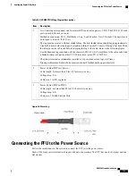
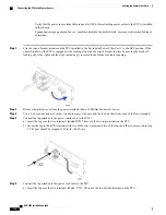
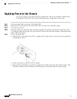
Connecting the PFU to the Power Source, page 129
Power Considerations
Each chassis supports one or two 165-amp PFUs.
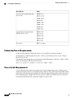
The following table describes the power requirements for the chassis.
These requirements are guidelines to assure that the cabling for your system meets safety requirements.
Note
Table 46: Chassis Power Requirements
Value
Characteristic
Maximum range:
-40VDC to -60VDC
Nominal range:
-48VDC to -60 VDC
Input Voltage
165A @ -48 VDC
TUV Rated Peak Current Load
5760W
Maximum Peak Power Load
800W
Empty Chassis Maximum Power Load
(includes fan trays)
ASR 5000 Installation Guide
125
Summary of Contents for ASR 5000
Page 16: ...ASR 5000 Installation Guide xvi About this Guide Contacting Customer Support ...
Page 64: ...ASR 5000 Installation Guide 48 Installation Procedure Overview Laser Notice ...
Page 100: ...ASR 5000 Installation Guide 84 Line Card Installation Installing the XGLC ...
Page 122: ...ASR 5000 Installation Guide 106 Cabling the Fast Ethernet 10 100 Line Card FLC2 Interfaces ...
Page 206: ...ASR 5000 Installation Guide 190 Removing and Installing SMC PC Cards Removing PC Cards ...
Page 212: ...ASR 5000 Installation Guide 196 Replacing the Chassis Air Filter Installing the Air Filter ...
Page 220: ...ASR 5000 Installation Guide 204 Replacing a Power Filter Unit What to do with the Failed PFU ...
Page 266: ...ASR 5000 Installation Guide 250 Safety Electrical and EMC Certifications Korean EMC ...
Page 270: ...ASR 5000 Installation Guide 254 Environmental Specifications Chassis Air Flow ...

