background image


6-18

Firepower 8000 Series Hardware Installation Guide


Chapter 6      Deploying Firepower Managed Devices

  Complex Network Deployments

Complex Network Deployments

Your enterprise’s network may require remote access, such as using a VPN, or have multiple entry 
points, such as a business partner or banking connection.

Integrating with VPNs

Virtual private networks, or VPNs, use IP tunneling techniques to provide the security of a local network 
to remote users over the Internet. In general, VPN solutions encrypt the data payload in an IP packet. 
The IP header is unencrypted so that the packet can be transmitted over public networks in much the 
same way as any other packet. When the packet arrives at its destination network, the payload is 
decrypted and the packet is directed to the proper host.

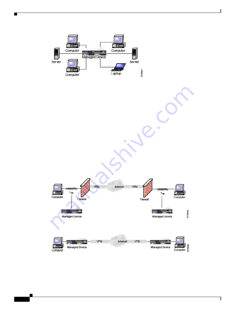
Because network appliances cannot analyze the encrypted payload of a VPN packet, placing managed 
devices outside the terminating endpoints of the VPN connections ensures that all packet information 
can be accessed. The following diagram illustrates how managed devices can be deployed in a VPN 
environment.

You can replace the firewall and the tap on either side of the VPN connection with the managed device. 
Note that if you replace the tap with a managed device, you lose the tap packet delivery guarantee.

Summary of Contents for AMP8050

Page 1: ... has more than 200 offices worldwide Addresses phone numbers and fax numbers are listed on the Cisco website at www cisco com go offices Firepower 8000 Series Hardware Installation Guide First Published July 22 2016 Last Updated May 5 2017 ...

Page 2: ... OR IMPLIED INCLUDING WITHOUT LIMITATION THOSE OF MERCHANTABILITY FITNESS FOR A PARTICULAR PURPOSE AND NONINFRINGEMENT OR ARISING FROM A COURSE OF DEALING USAGE OR TRADE PRACTICE IN NO EVENT SHALL CISCO OR ITS SUPPLIERS BE LIABLE FOR ANY INDIRECT SPECIAL CONSEQUENTIAL OR INCIDENTAL DAMAGES INCLUDING WITHOUT LIMITATION LOST PROFITS OR LOSS OR DAMAGE TO DATA ARISING OUT OF THE USE OR INABILITY TO US...

Page 3: ...eries Devices 2 1 Firepower 8000 Series Chassis Front View 2 2 Firepower 8000 Series Chassis Rear View 2 6 Firepower 8000 Series Physical and Environmental Parameters 2 9 Firepower 8000 Series Modules 2 12 Installing a Firepower 8000 Series Device 3 1 Unpacking and Inspecting the Appliance 3 1 Security Considerations 3 2 Identifying the Management Interfaces 3 2 Firepower 8000 Series 3 2 Identifyi...

Page 4: ...Single Management Interface 5 2 Multiple Management Interfaces 5 2 Deployment Options 5 3 Deploying with Traffic Channels 5 3 Deploying with Network Routes 5 4 Security Considerations 5 5 Special Case Connecting 8000 Series Devices 5 5 Deploying Firepower Managed Devices 6 1 Sensing Deployment Considerations 6 1 Understanding Sensing Interfaces 6 1 Passive Interfaces 6 2 Inline Interfaces 6 2 Swit...

Page 5: ...irepower 8000 Series Devices A 1 Warnings and Cautions A 1 Static Control A 1 Firepower 81xx Family Appliances A 1 AC Installation A 2 DC Installation A 3 Grounding Earthing Requirements A 4 Firepower 82xx Family Appliances A 5 AC Installation A 6 DC Installation A 7 Grounding Earthing Requirements A 8 Firepower and AMP 83xx Family Appliances A 9 AC Installation A 10 DC Installation A 11 Grounding...

Page 6: ... Before You Begin C 2 Malware Storage Pack Kit for 1U Devices C 3 Malware Storage Pack Kit for 2U Devices C 3 Installation C 4 Installing a Malware Storage Pack During an Upgrade C 4 Installing a Malware Storage Pack on a Version 6 0 1 Device C 5 Instructions for the 81xx Family Devices C 5 Instructions for the 82xx Family and 83xx Family Devices C 8 Post Installation C 11 Removing a Malware Stora...

Page 7: ...ws Chapter Title Description Chapter 1 About the Firepower 8000 Series Provides an overview of the devices included in the 8000 Series Chapter 2 Hardware Specifications Describes the hardware specifications for the Firepower 8000 Series models Chapter 3 Installing a Firepower 8000 Series Device Describes how to install a Firepower 8000 Series device in a rack how to connect the management interfac...

Page 8: ...n Indication bold type Commands and keywords and user entered text appear in bold type italic type Document titles new or emphasized terms and arguments for which you supply values are in italic type Elements in square brackets are optional x y z Required alternative keywords are grouped in braces and separated by vertical bars x y z Optional alternative keywords are grouped in brackets and separa...

Page 9: ...e viii Installation Instructions Warning page viii Chassis Warning for Rack Mounting and Servicing page viii Short Circuit Protection Warning page viii SELV Circuit Warning page viii Ground Conductor Warning page viii Faceplates and Cover Panels Warning page ix Product Disposal Warning page ix Compliance with Local and National Electrical Codes Warning page ix Grounded Equipment Warning page ix Sa...

Page 10: ...mounting this unit in a partially filled rack load the rack from the bottom to the top with the heaviest component at the bottom of the rack If the rack is provided with stabilizing devices install the stabilizers before mounting or servicing the unit in the rack Statement 1006 Short Circuit Protection Warning Warning This product requires short circuit overcurrent protection to be provided as par...

Page 11: ...des Warning Warning Installation of the equipment must comply with local and national electrical codes Statement 1074 Grounded Equipment Warning Warning This equipment is intended to be grounded Ensure that the host is connected to earth ground during normal use Statement 39 Safety Cover Requirement Warning The safety cover is an integral part of the product Do not operate the unit without the saf...

Page 12: ... Documentation and Submitting a Service Request For information on obtaining documentation using the Cisco Bug Search Tool BST submitting a service request and gathering additional information see What s New in Cisco Product Documentation at http www cisco com c en us td docs general whatsnew whatsnew html Subscribe to What s New in Cisco Product Documentation which lists all new and revised Cisco...

Page 13: ... traffic based on multiple criteria You must manage Firepower 8000 Series devices with a Firepower Management Center Warning Only trained and qualified personnel should install replace or service this equipment Statement 49 Firepower 8000 Series Managed Devices Delivered with Firepower System The following table lists the Firepower 8000 Series managed devices that Cisco delivers with the Firepower...

Page 14: ... appears on the regulatory label on the outside of the chassis and is the official reference code for hardware certifications and safety Table 1 2 8000 Series Chassis Models Firepower and AMP Device Model Hardware Chassis Code AMP8050 AC or DC power CHAS 1U AC DC 8120 8130 8140 AMP8150 AC or DC power CHAS 1U AC DC 8250 8260 8270 8290 AC or DC power CHAS 2U AC DC 8350 8360 8370 8390 AC or DC power ...

Page 15: ...together using the 8000 Series stacking cable See Using Devices in a Stacked Configuration page 3 10 for more information The Firepower 8000 Series device can be delivered on a variety of chassis AMP8050 is a 1U chassis and can contain up to three modules Firepower 8120 8130 8140 and AMP8150 also known as the 81xx Family is a 1U chassis and can contain up to three modules For the Firepower 8140 on...

Page 16: ... configuration Firepower 8390 and AMP8390 part of the 83xx Family is an 8U configuration with four 2U chassis The primary chassis contains three stacking modules and up to four sensing modules Each secondary chassis contains one stacking module This model is fully configured and does not accept a stacking kit Note The AMP models have many of the same form factors as their Firepower counterparts bu...

Page 17: ...ont panel for the Firepower and AMP 81xx Family 82xx Family and 83xx Family contain the same components Figure 2 3 Firepower 81xx Family Front Panel Table 2 1 Firepower 8000 Series System Components Front View Feature Description Module slots Contain the modules For information on available modules see Firepower 8000 Series Modules page 2 12 LCD panel Operates in multiple modes to configure the de...

Page 18: ...activity Green indicates there is network activity If the light is off there is no network activity Hard drive activity Indicates the hard drive status Blinking green indicates the fixed disk drive is active Amber indicates a fixed disk drive fault If the light is off there is no drive activity or the system is powered off System status Indicates the system status Green indicates the system is ope...

Page 19: ...ly installed processors or processor incompatibility critical event logging errors including System Memory Uncorrectable ECC error and fatal uncorrectable bus errors such as PCI SERR and PERR Non critical A non critical condition is a threshold crossing associated with the following events temperature voltage or fan non critical threshold crossing chassis intrusion Set Fault Indication command fro...

Page 20: ... the chassis contains connection ports the management interface and the power supplies Figure 2 5 AMP8x50 and Firepower 81xx Family Chassis CHAS 1U AC DC Rear View Firepower 82xx Family Chassis Rear View The rear view of the chassis contains power supplies connection ports and the management interface Figure 2 6 Firepower 82xx Family Chassis CHAS 2U AC DC Rear View Firepower and AMP 83xx Family Ch...

Page 21: ...ect access to all of the management services on the device The RJ45 serial port is used for maintenance and configuration purposes only and is not intended to carry service traffic RS232 serial port 83xx Family Allows you to establish a direct workstation to appliance connection for direct access to all of the management services on the device The RJ232 serial port is used for maintenance and conf...

Page 22: ...he link is up A light indicates the link is up No light indicates there is no link Table 2 7 Firepower 8000 Series Power Supply LEDs LED Description Off The power supply is not plugged in Amber No power supplied to this module or A power supply critical event such as module failure a blown fuse or a fan failure the power supply shuts down Blinking amber A power supply warning event such as high te...

Page 23: ...s multimode fiber 850 nm at 550 m standard Copper 1000BASE T non bypass NetMod Quad port Gigabit copper Ethernet non bypass interfaces in a paired configuration Cable and distance Cat5E at 50 m Fiber 10GBASE non bypass MMSR or SMLR NetMod Quad port fiber non bypass interfaces with LC connectors Cable and distance LR is single mode at 5000 m available SR is multimode fiber 850 nm at 550 m standard ...

Page 24: ...ir at the front of the appliance Table 2 9 AMP8x50 and 81xx Family Physical and Environmental Parameters continued Parameter Description Table 2 10 Firepower 82xx Family and Firepower and AMP 83xx Family Physical and Environmental Parameters Parameter Description Form factor 2U Dimensions D x W x H 29 0 in x 17 2 in x 3 48 in 73 5 cm x 43 3 cm x 88 2 cm Weight maximum installed 82xx Family 58 lbs ...

Page 25: ...mily Dual 1000 W redundant power supplies designed for AC or DC AC Voltage 100 VAC to 240 VAC nominal 85 VAC to 264 VAC maximum AC Current 11A maximum over the full range per supply 5 5A maximum for 187 VAC to 264 VAC per supply AC Frequency range 47 Hz to 63 Hz DC Voltage 48 VDC nominal referenced to RTN 40 VDC to 72 VDC maximum DC Current 25A maximum per supply Operating temperature 82xx Family ...

Page 26: ... 1000BASE T Copper Non Bypass NetMod page 2 18 for more information a quad port 1000BASE SX fiber interface without bypass capability See Quad Port 1000BASE SX Fiber Non Bypass NetMod page 2 18 for more information a quad port 10GBASE MMSR or SMLR fiber interface without bypass capability See Quad Port 10GBASE MMSR or SMLR Fiber Non Bypass NetMod page 2 19 for more information In addition you can ...

Page 27: ...ins four fiber ports and link activity and bypass LEDs Use the following table to understand link and activity LEDs of the fiber interfaces Table 2 11 Copper Link Activity LEDs Status Description Both LEDs off The interface does not have link and is not in bypass mode Link amber The speed of the traffic on the interface is 10Mb or 100Mb Link green The speed of the traffic on the interface is 1Gb A...

Page 28: ...he light is always on Table 2 14 Fiber Bypass LEDs Status Description Off The interface does not have link and is not in bypass mode Steady green The interface has link and is passing traffic Steady amber The interface has been intentionally brought down Blinking amber The interface is in bypass mode that is it has failed open Table 2 15 1000BASE SX NetMod Optical Parameters Parameter 1000BASE SX ...

Page 29: ...e interface A blinking light indicates the interface has activity No light indicates there is no activity Bottom For an inline interface A light indicates the interface has activity No light indicates there is no activity For a passive interface the light is always on Table 2 17 Fiber Bypass LEDs Status Description Off The interface does not have link and is not in bypass mode Steady green The int...

Page 30: ... 860 nm 850 nm typical 85 ft 26 m to 108 ft 33 m for 62 5 µm 125 µm fiber modal BW 160 to 200 respectively 216 ft 66 m to 269 ft 82 m for 50 µm 125 µm fiber modal BW 400 to 500 respectively Distances to 980 ft 300 m are available with higher quality OM3 fiber Minimum distances all 6ft 2 m 1270 1355 nm 1310 nm typical 6 ft to 6 2 miles 2 m to 10 km for 9 µm 125 µm fiber Transmitter wavelength 840 8...

Page 31: ...ctivity The light flashes when the interface has activity If dark there is no activity Bottom link The light is on when the interface has link If dark there is no link Table 2 20 Fiber Bypass LED Status Description Off The interface pair does not have link and is not in bypass mode or has no power Steady green The interface pair has link and is passing traffic Steady amber The interface has been i...

Page 32: ...fiber ports and link and activity LEDs Use the following table to understand the link and activity LEDs on the fiber interfaces Minimum average launch power 7 8 dBm Maximum average power at receiver 2 4 dBm Receiver sensitivity 9 5 dBm Table 2 21 40GBASE SR4 NetMod Optical Parameters continued Parameter 40GBASE SR4 Table 2 22 Non Bypass Copper Link Activity LEDs Status Description Both LEDs Off Th...

Page 33: ... Fiber Link Activity LEDs Status Description Top Activity For an inline or passive interface the light flashes when the interface has activity If dark there is no activity Bottom Link For an inline interface the light is on when the interface has link If dark there is no link For a passive interface the light is always on Table 2 24 1000BASE SX NetMod Optical Parameters Parameter 1000BASE SX Optic...

Page 34: ...ameters Parameter 10GBASE MMSR 10GBASE SMLR Optical connectors LC duplex LC duplex Bit rate 10 000Gbps 10 000Gbps Baud rate encoding tolerance 10 3125Gbps 64 66b encoding 100 ppm 10 3125Gbps 64 66b encoding 100 ppm Optical interface Multimode Single mode only Operating distance 840 860 nm 850 nm typical 85 ft 26 m to 108 ft 33 m for 62 5 µm 125 µm fiber modal BW 160 to 200 respectively 216 ft 66 m...

Page 35: ...following 8000 Series stacked configurations Firepower 8260 8270 and 8290 Firepower and AMP 8360 8370 and 8390 You can use the following table to understand the stacking LEDs Table 2 27 Stacking LEDs Status Description Top Indicates activity on the interface A blinking light indicates there is activity on the interface No light indicates there is no activity Bottom Indicates whether the interface ...

Page 36: ...2 22 Firepower 8000 Series Hardware Installation Guide Chapter 2 Hardware Specifications Firepower 8000 Series Devices ...

Page 37: ...on see Firepower Management Center Configuration Guide You can pre configure multiple appliances at one location to be used in different deployment locations For guidance on pre configuring see the Firepower 8000 Series Getting Started Guide Unpacking and Inspecting the Appliance Tip Keep the shipping container in case the server requires shipping in the future Note The chassis is thoroughly inspe...

Page 38: ...specific workstation IP addresses that can be allowed to access appliances Restrict access to the appliance to only those specific hosts using Access Lists within the appliance s system policy For more information see the Firepower Management Center Configuration Guide Identifying the Management Interfaces You connect each appliance in your deployment to the network using the management interface ...

Page 39: ...epower 8000 Series page 3 3 To locate the module slots on the 8000 Series on the Firepower 8000 Series page 3 3 To locate the sensing interfaces on the 8000 Series NetMods see Firepower 8000 Series Modules page 3 4 For information on connection types see Understanding Sensing Interfaces page 6 2 Firepower 8000 Series The 8000 Series is available as a 1U device with a 10G network switch or a 2U dev...

Page 40: ...ore identically configured appliances The stacking module is optional on the Firepower 8140 8250 and 8350 and is provided in the Firepower 8260 8270 8290 and the Firepower and AMP 8360 8370 8390 stacked configurations Caution Modules are not hot swappable See Inserting and Removing Firepower 8000 Series Modules page B 1 for more information The following illustrations of the front of the chassis i...

Page 41: ...lity See Figure 3 9Quad Port 1000BASE SX Fiber Non Bypass NetMod page 3 8 for more information a quad port 10GBASE MMSR or SMLR fiber interface without bypass capability See Figure 3 10Quad Port 10GBASE MMSR or SMLR Fiber Non Bypass NetMod page 3 8 for more information A stacking module is optional on the Firepower 8140 8250 and 8350 and is provided in the Firepower 8260 8270 8290 and the Firepowe...

Page 42: ... flow even if the device fails or loses power You must also use the web interface to configure a pair of interfaces as an inline set and enable bypass mode on the inline set Figure 3 5 Dual Port 10GBASE MMSR or SMLR Fiber Configurable Bypass NetMod The dual port 10GBASE fiber configurable bypass configuration uses LC type Local Connector optical transceivers Note that these can be either MMSR or S...

Page 43: ...he 40G interface screen on its managing Firepower Management Center web interface displays red A 40G capable 8250 displays 8250 40G on the LCD Panel and a 40G capable 8350 displays 8350 40G on the LCD Panel You can use this configuration to passively monitor up to two separate network segments You also can use the paired interface in inline or inline with bypass mode which allows you to deploy the...

Page 44: ...four separate network segments You also can use paired interfaces in inline configuration on up to two network segments Tip For best performance use the interface sets consecutively If you skip interfaces you may experience degraded performance Figure 3 10 Quad Port 10GBASE MMSR or SMLR Fiber Non Bypass NetMod The quad port 10GBASE fiber non bypass configuration uses LC type Local Connector optica...

Page 45: ...an be delivered with the stacking module The Firepower 8260 stacked configuration is delivered with one stacking module in the primary device and one stacking module in the secondary device The Firepower and AMP 8360 stacked configurations are delivered with one stacking module in the primary device and one stacking module in the secondary device The Firepower 8270 stacked configuration is deliver...

Page 46: ...Firepower or AMP 8360 a 40G capable primary device and a secondary device a Firepower or AMP 8370 a 40G capable primary device and two secondary devices a Firepower or AMP 8390 a 40G capable primary device and three secondary devices For the Firepower 8260 and 8270 devices and Firepower or AMP 8360 and 8370 devices you can stack additional devices for a total of four devices in the stack One devic...

Page 47: ...e left stacking interface on the primary device to the left stacking interface on the secondary device then use the Firepower Management Center that manages the devices to establish the stacked device relationship in the system Note that the right stacking interface is not connected See Managing Stacked Devices page 3 15 Caution You must have management interfaces configured and working for all de...

Page 48: ...mary device as required for the number of secondary devices in the configuration Caution You must have management interfaces configured and working for all device stack members Register all devices as single devices stack them and never remove or disable the management interfaces for stacked secondary devices This allows each stack member to report health and exchange configuration information 825...

Page 49: ...d secondary devices For each configuration 8270 or 8370 one secondary device is installed above the primary device and the other is installed below the primary device 8290 or 8390 Primary Device 40G and Three Secondary Devices The following example shows a Firepower 8290 or a 8390 Firepower or AMP configuration The Firepower 8290 includes a 40G capable 8250 primary device and three dedicated secon...

Page 50: ...ondary device Step 3 Repeat steps 1 and 2 for each secondary device you want to connect Step 4 Use the Firepower Management Center that manages the devices to establish the stacked device relationship and manage their joint resources See Managing Stacked Devices page 3 15 Caution You must have management interfaces configured and working for all device stack members Register all devices as single ...

Page 51: ... up then insert the keyed end into the port on the stacking module until you hear the latch click into place To remove an 8000 Series stacking cable Step 1 To remove the cable pull on the release tab to release the latch then remove the cable end Managing Stacked Devices A Firepower Management Center establishes the stacked relationship between the devices controls the interface sets of the primar...

Page 52: ...cess the console in the following additional ways Serial Connection Laptop You can connect a computer to any Firepower device using the physical serial port Connect the appropriate rollover serial cable also known as a NULL modem cable or Cisco console cable at any time then configure the remote management console to redirect the default VGA output to the serial port To interact with the appliance...

Page 53: ...ork segment you want to analyze Fiber Tap If you are deploying the device with an optional fiber optic tap connect the SC plug on the optional multimode fiber cable to the analyzer port on the tap Connect the tap to the network segment you want to analyze Copper Tap If you are deploying the device with an optional copper tap connect the A and B ports on the left of the tap to the network segment y...

Page 54: ...on configuring an interface set for inline bypass mode To test a device with inline bypass interface installation Access Admin Step 1 Set all interfaces on the switch the firewall and the device sensing interfaces to auto negotiate Note Firepower System devices require auto negotiate when using auto MDIX on the device Step 2 Power off the device and disconnect all network cables Reconnect the devi...

Page 55: ... following sets of conditions device powered off device powered on policy with no rules applied inline intrusion policy protection mode device powered on policy with no rules applied inline intrusion policy protection tap mode device powered on policy with tuned rules applied inline intrusion policy protection mode Ensure that the latency periods are acceptable for your installation For informatio...

Page 56: ...3 20 Firepower 8000 Series Hardware Installation Guide Chapter 3 Installing a Firepower 8000 Series Device Testing an Inline Bypass Interface Installation ...

Page 57: ...tion Mode page 4 4 explains how to use the LCD panel to configure the network configuration for the device s management interface the IPv4 or IPv6 address subnet mask or prefix and default gateway Caution Allowing reconfiguration using the LCD panel may present a security risk You need only physical access not authentication to configure using the LCD panel System Status Mode page 4 6 explains how...

Page 58: ...Display mode which does not include a key map Figure 4 1 LCD Panel Idle Display mode In Idle Display mode the panel alternates between displaying the CPU utilization and free memory available and the chassis serial number Press any key to interrupt the Idle Display mode and enter the LCD panel s main menu where you can access Network Configuration System Status and Information modes The following ...

Page 59: ...lti function key functions Idle Display Mode The LCD panel enters Idle Display mode after 60 seconds of inactivity you have not pressed any multi function keys with no detected errors If the system detects an error the panel enters Error Alert mode see Error Alert Mode page 4 9 until the error is resolved Idle Display mode is also disabled when you are editing your network configuration or running...

Page 60: ...ult gateway If you edit the IP address of a Firepower device using the LCD panel confirm that the changes are reflected on the managing Management Center In some cases you may need to edit the device management settings manually See the for more information By default the ability to change network configuration using the LCD panel is disabled You can enable it during the initial setup process or u...

Page 61: ...IP address To edit the digit press the minus or plus keys on the top row to decrease or increase the digit by one To move to the next digit in the IP address press the right arrow key on the bottom row to move the cursor to the next digit to the right With the cursor on the first digit the LCD panel displays the cancel and right arrow symbols at the end of the IP address With the cursor on any oth...

Page 62: ...escribed in the following procedure To allow network reconfiguration using a device s LCD panel Access Admin Step 1 After you complete the initial setup of the device log into the device s web interface using an account with Administrator privileges Step 2 Select System Local Configuration The Information page appears Step 3 Click Network The Network Settings page appears Step 4 Under LCD Panel se...

Page 63: ... scroll through the options by pressing the down arrow â key until the LCD panel displays the LCD Brightness and LCD Contrast options LCD Brightness Table 4 2 System Status Mode Options Option Description Resources Displays the CPU utilization and free memory available Note that Idle Display mode also shows this information Link State Displays a list of any inline sets currently in use and the lin...

Page 64: ...ber IP address model and software and firmware versions Support may require this information if you call for assistance The following table describes the information available in this mode To enter Information mode and view identifying system information Step 1 In Idle Display mode press any multi function key to enter the main menu The main menu appears Network Config System Status Step 2 Scroll ...

Page 65: ... error conditions are resolved The LCD panel always displays the platform daemon error message first followed by a list of other hardware error messages The following table provides basic information on Firepower device error messages where X indicates the NFE accelerator card 0 or 1 that generated the alert Table 4 4 LCD Panel Error Alerts Error Description Hardware alarm Alerts on hardware alarm...

Page 66: ...ou resolve the error that triggered the alert the LCD panel returns to Error Alert mode Contact Support for assistance NFEMessDX message daemon Alerts when the message daemon fails NFEHardware hardware status Alerts when one or more accelerator cards is not communicating NFEcount cards detected Alerts when the number of accelerator cards detected on the device does not match the expected accelerat...

Page 67: ...fficient and effective system Will you use the default single management interface to connect your device to your Management Center Will you enable additional management interfaces to improve performance or to isolate traffic received on the Management Center from different networks See Understanding Management Interfaces page 5 2 for more information Do you want to enable traffic channels to crea...

Page 68: ...he default configuration to enable traffic channels and multiple management interfaces using the web interface on each appliance For configuration information see Configuring Appliance Settings in the Firepower Management Center Configuration Guide Management interfaces are often located on the back of the appliance See Identifying the Management Interfaces page 3 2 for more information Single Man...

Page 69: ...or more management interfaces on the Management Center However because the 70xx Family contains only one management interface the device receives traffic sent from the Management Center on only one management interface Deployment Options You can manage traffic flow using traffic channels to improve performance on your system using one or more management interfaces In addition you can create a rout...

Page 70: ...erface for event traffic channels Deploying with Network Routes You can create a route from a specific management interface on your Management Center to a different network When you register a device from that network to the specified management interface on the Management Center you provide an isolated connection between the Management Center and the device on a different network Configure both t...

Page 71: ... network that is protected from unauthorized access Identify the specific workstation IP addresses that can be allowed to access appliances Restrict access to the appliance to only those specific hosts using Access Lists within the appliance s system policy For more information see the Firepower Management Center Configuration Guide Special Case Connecting 8000 Series Devices Supported Devices 800...

Page 72: ...5 6 Firepower 8000 Series Hardware Installation Guide Chapter 5 Deploying on a Management Network Special Case Connecting 8000 Series Devices ...

Page 73: ...at penetrate your firewall Do you have specific assets on your network such as financial accounting or personnel records production code or other sensitive protected information that require special security policies See Deployment Options page 6 7 for more information Will you use multiple sensing interfaces on your managed device to recombine the separate connections from a network tap or to cap...

Page 74: ...segment and on another network segment you cannot permit uninspected traffic Using configurable bypass inline sets you can manage the traffic flow of your network traffic in one of the following ways Bypass an interface pair configured for bypass allows all traffic to flow if the device fails The traffic bypasses the device and any inspection or other processing by the device Bypass allows uninspe...

Page 75: ...u can configure your device as a virtual switch and use the remaining interfaces to connect to network segments you want to monitor To use a virtual switch on your device create physical switched interfaces and then follow the instructions for Setting Up Virtual Switches in the Firepower Management Center Configuration Guide Routed Interfaces You can configure routed interfaces on a Firepower devi...

Page 76: ...aces with network address translation NAT to pass traffic between networks For more information see Deploying with Policy Based NAT page 6 11 If you want to use hybrid interfaces on your device define a hybrid interface on the device and then follow the instructions for Setting Up Hybrid Interfaces in the Firepower Management Center Configuration Guide Connecting Devices to Your Network You can co...

Page 77: ...he switch By design network taps divide incoming and outgoing traffic into two different streams over two different cables Managed devices offer multiple sensing interface options that recombine the two sides of the conversation so that the entire traffic stream is evaluated by the decoders the preprocessors and the detection engine Cabling Inline Deployments on Copper Interfaces If you deploy you...

Page 78: ...ould repeat the process of ensuring that the endpoints can communicate with the new device powered down to protect against the case where the original device and its replacement have different bypass characteristics The Auto MDI X setting functions correctly only if you allow the network interfaces to auto negotiate If your network environment requires that you turn off the Auto Negotiate option o...

Page 79: ...l switch to allow traffic you configure two or more switched interfaces on a physical port add and configure a virtual switch and then assign the virtual switch to the switched interfaces The system drops any traffic received on an external physical interface that does not have a switched interface waiting for it If the system receives a packet with no VLAN tag and you have not configured a physic...

Page 80: ... use a virtual router with a gateway VPN For more information see Deploying a Gateway VPN page 6 10 A virtual router can contain either physical or logical routed configurations from one or more individual devices within the same broadcast domain You must associate each logical interface with a VLAN tag to handle traffic received by the physical interface with that specific tag You must assign a l...

Page 81: ... See Deploying with Policy Based NAT page 6 11 A hybrid interface must contain one or more switched interfaces and one or more routed interfaces A common deployment consists of two switched interfaces configured as a virtual switch to pass traffic on a local network and virtual routers to route traffic to networks either private or public To create a hybrid interface you first configure a virtual ...

Page 82: ...nd the local gateway can connect to the hosts behind the remote gateway through the secure VPN tunnel The VPN endpoints authenticate each other with either the Internet Key Exchange IKE version 1 or version 2 protocol to create a security association for the tunnel The system runs in either IPSec authentication header AH mode or the IPSec encapsulating security payload ESP mode Both AH and ESP pro...

Page 83: ... the public network Allow access to a private network service When a public network accesses your private network NAT translates your public address to your private network address The public network can access your specific private network address Redirect traffic between multiple private networks When a server on a private network accesses a server on a connected private network NAT translates t...

Page 84: ...e 6 12 explains how access control functions on traffic that passes through the firewall On the DMZ page 6 13 explains how access control within the DMZ can protect outward facing servers On the Internal Network page 6 14 explains how access control can protect your internal network from intentional or accidental attack On the Core Network page 6 14 explains how an access control policy with stric...

Page 85: ...ecific criteria On the DMZ The DMZ contains outward facing servers for example web FTP DNS and mail and may also provide services such as mail relay and web proxy to users on the internal network Content stored in the DMZ is static and changes are planned and executed with clear communication and advance notice Attacks in this segment are typically inbound and become immediately apparent because o...

Page 86: ...ition to outbound traffic Add access control rules to tightly control traffic between users and applications On the Core Network Core assets are those assets critical to the success of your business that must be protected at all cost Although core assets vary depending on the nature of your business typical core assets include financial and management centers or intellectual property repositories ...

Page 87: ...al devices for business purposes for example using a smart phone to access corporate email are becoming increasingly common These networks can be highly dynamic environments with rapid and continual change Deploying a managed device on a dedicated mobile or remote network allows you to create a strict access control policy to monitor and manage traffic to and from unknown external sources Your pol...

Page 88: ...put for which the device is rated the total traffic on the managed device cannot exceed its bandwidth rating without some packet loss Deploying multiple sensing interfaces on a managed device with a network tap is a straightforward process The following diagram shows a network tap installed on a high traffic network segment In this scenario the tap transmits incoming and outgoing traffic through s...

Page 89: ...at if you replace the tap with a virtual switch you lose the tap packet delivery guarantee You can also create interfaces to capture data from separate networks The following diagram shows a single device with a dual sensing interface adapter and two interfaces connected to two networks In addition to using one device to monitor both network segments you can use the virtual switch capability of th...

Page 90: ...ader is unencrypted so that the packet can be transmitted over public networks in much the same way as any other packet When the packet arrives at its destination network the payload is decrypted and the packet is directed to the proper host Because network appliances cannot analyze the encrypted payload of a VPN packet placing managed devices outside the terminating endpoints of the VPN connectio...

Page 91: ... of the Internet modem banks and direct links to business partner networks In general you should deploy managed devices near firewalls either inside the firewall outside the firewall or both and on network segments that are important to the integrity and confidentiality of your business data The following diagram shows how managed devices can be installed at key locations on a complex network with...

Page 92: ...rom managed devices deployed throughout the organization s many locations Unlike deploying multiple managed devices and Firepower Management Centers in the same geographic location on the same network when deploying managed devices in disparate geographic locations you must take precautions to ensure the security of the managed devices and the data stream To secure the data you must isolate the ma...

Page 93: ...r 8000 Series Hardware Installation Guide Chapter 6 Deploying Firepower Managed Devices Complex Network Deployments You can replace the firewalls and routers with the managed device deployed in each network segment ...

Page 94: ... allow you to add a management interface with a unique IP address IPv4 or IPv6 to your Firepower Management Center and create a route from that management interface to a network that contains the device you want to manage When you register your device to the new management interface traffic on that device is isolated from traffic on devices registered to the default management interface on the Fir...

Page 95: ... or NAT device In this case Cisco recommends that you position managed devices inside the network segment protected by the proxy or NAT device to ensure that hosts are correctly detected Integrating with Load Balancing Methods In some network environments server farm configurations are used to perform network load balancing for services such as web hosting FTP storage sites and so on In load balan...

Page 96: ...6 24 Firepower 8000 Series Hardware Installation Guide Chapter 6 Deploying Firepower Managed Devices Complex Network Deployments ...

Page 97: ...e 4 and require isolation from the exposed OSP cabling The addition of the primary protectors is not sufficient protection to connect these interfaces metallically to OSP wiring Static Control Caution Electrostatic discharge control procedures such as using grounded wrist straps and an ESD work surface must be in place before unpacking installing or moving the appliance Excessive electrostatic dis...

Page 98: ... the appliance Use an external Surge Protection Device at the input of the network equipment where the Firepower System is to be installed Separate Circuit Installation If separate circuits are used each one must be rated the full rating of the appliance This configuration provides for circuit failure and power supply failure Example Each supply is attached to a different 220V circuit Each circuit...

Page 99: ...er to each power supply to run the entire appliance The voltage and current ratings for each supply are listed on the label on the appliance Use an external Surge Protection Device at the input of the network equipment where the Firepower System is to be installed Separate Circuit Installation If separate circuits are used each circuit must be rated to the full rating of the appliance This configu...

Page 100: ...rovided The circuit breaker must meet the following requirements UL Recognized CSA Approved Recommended VDE Approved Recommended Support the maximum load 20A Support the installation voltage 40V to 72VDC as required by the power supply Rated for DC use A recommended breaker is Airpax IELK1 1 72 20 0 01 V The terminal option used will depend on the installation This breaker is a single pole 20A bre...

Page 101: ...t For AC circuits see AC Current page A 2 For DC currents see DC Current page A 4 Bare conductors must be coated with antioxidant before crimp connections are made Only copper cables can be used for grounding purposes DC Supplies The DC power supplies have additional ground connections on each supply This allows the hot swappable supply to be connected to power return and ground so that it may be ...

Page 102: ...on the appliance Use an external Surge Protection Device at the input of the network equipment where the Firepower System is to be installed Separate Circuit Installation If separate circuits are used each one must be rated the full rating of the appliance This configuration provides for circuit failure and power supply failure Example Each supply is attached to a different 220V circuit Each circu...

Page 103: ...er to each power supply to run the entire appliance The voltage and current ratings for each supply are listed on the label on the appliance Use an external Surge Protection Device at the input of the network equipment where the Firepower System is to be installed Separate Circuit Installation If separate circuits are used each circuit must be rated to the full rating of the appliance This configu...

Page 104: ...rovided The circuit breaker must meet the following requirements UL Recognized CSA Approved Recommended VDE Approved Recommended Support the maximum load 20A Support the installation voltage 40V to 72VDC as required by the power supply Rated for DC use A recommended breaker is Airpax IELK1 1 72 20 0 01 V The terminal option used will depend on the installation This breaker is a single pole 20A bre...

Page 105: ...d be equal to the current of the breaker used to protect the circuit For AC circuits see AC Current page A 2 For DC currents see DC Current page A 4 Bare conductors must be coated with antioxidant before crimp connections are made Only copper cables can be used for grounding purposes DC Supplies The DC power supplies have additional ground connections on each supply This allows the hot swappable s...

Page 106: ...e and current ratings for each supply are listed on the label on the appliance Use an external Surge Protection Device at the input of the network equipment where the Firepower System is to be installed Separate Circuit Installation If separate circuits are used each one must be rated the full rating of the appliance This configuration provides for circuit failure and power supply failure Example ...

Page 107: ...t power to each power supply to run the entire appliance The voltage and current ratings for each supply are listed on the label on the appliance Use an external Surge Protection Device at the input of the network equipment where the Firepower System is to be installed Separate Circuit Installation If separate circuits are used each circuit must be rated to the full rating of the appliance This co...

Page 108: ... be provided The circuit breaker must meet the following requirements UL Recognized CSA Approved Recommended VDE Approved Recommended Support the maximum load 20A Support the installation voltage 40V to 72VDC as required by the power supply Rated for DC use A recommended breaker is Airpax IELK1 1 72 20 0 01 V The terminal option used will depend on the installation This breaker is a single pole 20...

Page 109: ...d This is a UL approved ring terminal with a hole for a 8 stud Ground Wire Requirements The ground wire must be sized sufficiently to handle the current of the circuit in case of a single fault The size of the ground wire should be equal to the current of the breaker used to protect the circuit For AC circuits see AC Current page A 10 For DC currents see DC Current page A 12 Bare conductors must b...

Page 110: ...A 14 Firepower 8000 Series Hardware Installation Guide Appendix A Power Requirements for Firepower 8000 Series Devices Firepower and AMP 83xx Family Appliances ...

Page 111: ...configuration complete all procedures on the secondary units first then perform any replacements on the primary unit About Firepower 8000 Series Modules For a new appliance assemble your device before installing the Firepower System See the assembly instructions included with your NetMods Note Replacing a NetMod can alter the configuration of a fully configured Korean certified KCC mark Firepower ...

Page 112: ...eries Modules page 2 12 for complete information about Firepower 8000 Series modules Module Slots on the Firepower 8000 Series Devices The following illustrations of the front of the chassis indicates the location of the module slots that contain NetMods for sensing interfaces Firepower 81xx Family devices can use the modules in the following slots Figure B 3 Firepower 81xx Family Primary Device F...

Page 113: ...device See Using Devices in a Stacked Configuration page 3 10 for complete information about stacking See the 8000 Series Device Stacking chapter in the Firepower Management Center Configuration Guide for information about managing device stacks with your Firepower Management Center Included Items Your module assembly kit includes a T8 Torx screwdriver and one or more of the following modules quad...

Page 114: ...age appears in the web interface on the managing Management Center when you attempt to configure the NetMod Contact support for assistance Power Down the Appliance Caution You cannot hot swap NetMods You must power down and unplug both power cords from the appliance before inserting or removing modules Before You Begin Prepare to insert or remove your module using the following guidelines Identify...

Page 115: ... Device in a Stack in a High Availability Pair chapter in the Firepower Management Center Configuration Guide Remove the Module or Slot Cover Use proper electrostatic discharge ESD practices such as wearing wrist straps and using an ESD work surface when handling the modules Store unused modules in an ESD bag or box to prevent damage Procedure Step 1 Remove and reserve the T8 Torx screw from the l...

Page 116: ...arge ESD practices such as wearing wrist straps and using an ESD work surface when handling the modules Store unused modules in an ESD bag or box to prevent damage Procedure Step 1 Remove and reserve the T8 Torx screw from the lever of the module using the included screwdriver Step 2 Pull the lever away from the module to open the latch The near end of the latch is visible The far end of the latch...

Page 117: ...the Module or Slot Cover Step 3 Insert the module into the slot until the far end of the latch is inside the slot and the near end of the latch touches the outside of the module slot Correct module alignment Incorrect module alignment Step 4 Push the lever toward the module so that the latch engages and pulls the module into the slot ...

Page 118: ...r Caution Do not use excessive force If the latch does not engage remove and realign the module then try again Step 5 Press firmly on the screw hole to push the lever fully against the module to secure the latch The lever is fully against the module and the module is flush with the chassis Step 6 Insert and tighten the reserved T8 Torx screw into the lever ...

Page 119: ...liance is part of a device stack or high availability pair bring the device out of maintenance mode from the Firepower Management Center Choose Devices Device Management Next to the stack member or peer click the toggle maintenance mode icon to bring the device out of maintenance mode What to Do Next Configure the new interfaces See the Interface Configuration Settings chapter in the Firepower Man...

Page 120: ...k Modules Apply Changes to the Appliance Tip You can apply device changes from the Device Management page or from the Interfaces tab of the appliance editor Procedure Step 1 Select Devices Device Management Step 2 Next to the device where you want to apply changes click the apply icon Step 3 When prompted click Apply ...

Page 121: ...t if you require assistance with malware storage packs These instructions are for use with Firepower 8000 Series devices running version 5 3 or greater of the Firepower System and contains the following sections Malware Storage Pack Overview page C 1 Supported Devices page C 2 Before You Begin page C 2 Installation page C 4 Post Installation page C 11 Malware Storage Pack Overview Firepower 8000 S...

Page 122: ...reater of the Firepower System The following 8000 Series devices support the malware storage pack 81xx Family devices Firepower 8120 8130 8140 but not the AMP8150 82xx Family devices Firepower 8250 8260 8270 8290 83xx Family devices Firepower 8350 8360 8370 8390 You must be running version 5 3 or greater of the Firepower System software before you install the malware storage pack For additional gu...

Page 123: ...ge Pack Kit for 1U Devices page C 3 Malware Storage Pack Kit for 2U Devices page C 3 Malware Storage Pack Kit for 1U Devices The 81xx Family of devices requires a malware storage pack kit for the 1U chassis consisting of a malware storage pack installed in a chassis compatible SSD tray a T8 Torx driver an instruction guide this document Malware Storage Pack Kit for 2U Devices The 82xx Family and 8...

Page 124: ...the device see the Managing Devices chapter in the Firepower Management Center Configuration Guide Installing a Malware Storage Pack During an Upgrade Use the following procedure to install a malware storage pack in a device in the field and reimage the Firepower System To install a malware storage pack during a customer upgrade Step 1 Shut down the system Step 2 Power off the device Step 3 Instal...

Page 125: ...Install the malware storage pack For 81xx Family devices refer to Blue Instructions for the 81xx Family Devices on page 5 For 82xx Family and 83xx Family devices refer to Blue Instructions for the 82xx Family and 83xx Family Devices on page 8 Step 4 Turn on the system Refer to Blue Post Installation on page 11 for information on restarting a device after a second SSD has been installed Instruction...

Page 126: ...ck Note Use proper electrostatic discharge ESD practices such as wrist straps and an ESD work surface Step 1 Ensure the device is powered off before you begin to install or remove a malware storage pack Step 2 Use the T8 Torx driver to remove the Torx screw on the right side of the second SSD tray Retain the screw Step 3 Unscrew and pull on the thumbscrew to remove the empty SSD tray from the devi...

Page 127: ...nsert the malware storage pack into the device Step 6 Tighten the thumb screw on the malware storage pack to secure the storage pack into the device Step 7 Use the T8 Torx driver to replace the screw removed in Step 1 Step 8 Turn on the system Refer to Blue Post Installation on page 11 for information on restarting a device after a malware storage pack has been installed ...

Page 128: ... storage pack SSD in the following 8000 Series devices with 2U chassis 82xx Family devices Firepower 8250 8260 8270 8290 83xx Family devices Firepower 8350 8360 8370 8390 82xx Family Chassis Rear View The SSD trays are located on the rear of the 82xx Family chassis Figure C 3 82xx Family Rear View 83xx Family Chassis Rear View The SSD trays are located on the rear of the 83xx Family chassis Figure...

Page 129: ...ve the empty SSD tray and replace it with the appropriate malware storage pack Note Use proper electrostatic discharge ESD practices such as wrist straps and an ESD work surface Step 1 Ensure the device is powered off before you begin to install or remove a malware storage pack Step 2 Use the 3 mm hex wrench to unlock the latch release on the bottom SSD tray by turning the hex screw one quarter tu...

Page 130: ...emove the malware storage pack at any time re install the empty tray in the device Step 5 Remove the malware storage pack from its packaging Step 6 Press the latch lock to release the latch handle The latch handle opens toward you Note If the latch release is locked use the 3 mm hex wrench to unlock the latch release on the malware storage pack by turning the hex screw one quarter turn counter clo...

Page 131: ...k the latch release on the malware storage pack by turning the hex screw one quarter turn clockwise towards the lock icon Step 10 Turn on the system Refer to Blue Post Installation on page 11 for information on restarting a device after a malware storage pack has been installed Post Installation After installation of a malware storage pack is completed you can restart the device to resume normal o...

Page 132: ...ia a console warning message that file capture data is being transferred from the primary SSD The file transfer process can take five or more minutes Do not reboot or otherwise interrupt this process Note that you can remove a malware storage pack from a device at any time A malware storage pack with file capture data can be relocated to another compatible device running Firepower System Any file ...

Page 133: ...Guide Monitoring a Malware Storage Pack Use the Firepower System to monitor your malware storage pack The Firepower System provides information on usage including the percentage of space used on the malware storage pack and the capacity of the malware storage pack The Firepower System also provides many useful monitoring features to assist you in the daily administration of your system including h...

Page 134: ...C 14 Firepower 8000 Series Hardware Installation Guide Appendix C Installing a Malware Storage Pack Post Installation ...

Reviews: