background image

10


e.

CAPWAP UDP ports (UDP 5246/5247) must not be blocked in the network.

f.

The access point must be able to find the IP address of the controller. This can be 
accomplished using DHCP, DNS, or IP subnet broadcast. This guide describes the DHCP 
method to convey the controller IP address. For other methods, refer to the product 
documentation. See also the “Using DHCP Option 43” section on page 15 for more 
information.

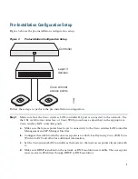
Step 2

Apply power to the access point:

a.

The access point is 802.3af (15.4 W) compliant and can be powered by any of the following 
802.3af compliant devices:

2106 controller

WS-C3550, WS-C3560, and WS-C3750 switches

C1880 switch

2600, 2610, 2611, 2621, 2650, and 2651 multiservice platforms

2610XM, 2611XM, 2621XM, 2650XM, 2651XM, and 2691 multiservice platforms

2811, 2821, and 2851 integrated services routers

3620, 3631-telco, 3640, and 3660 multiservice platforms

3725 and 3745 multiservice access routers

3825 and 3845 integrated services routers

The recommended external power supply for the access point is the Cisco AIR-PWR-B 
power supply. The access point can also be powered by the following optional external 
power sources: 

Any 802.3af compliant power injector

Note

The 1260 series access point requires a Gigibit Ethernet link to prevent the Ethernet 
port from becoming a bottleneck for traffic because wireless traffic speeds exceed 
transmit speeds of a 10/100 Ethernet port.

1250 series access point power injector (AIR-PWRINJ4)

b.

As the access point attempts to connect to the controller, the LEDs cycle through a green, red, 
and amber sequence, which can take up to 5 minutes.

Note

If the access point remains in this mode for more than five minutes, the access point is 
unable to find the Master Cisco wireless LAN controller. Check the connection between 
the access point and the Cisco wireless LAN controller and be sure that they are on the 
same subnet. 

Summary of Contents for Aironet 1260 Series

Page 1: ...ew 5 Configuring the Access Point 6 Additional Configuration for the Access Point in Autonomous Mode 7 Mounting the Access Point 8 Deploying the Access Point on the Wireless Network 9 Troubleshooting 10 Declarations of Conformity and Regulatory Information 11 Configuring DHCP Option 43 and DHCP Option 60 12 Access Point Specifications ...

Page 2: ...NS This warning symbol means danger You are in a situation that could cause bodily injury Before you work on any equipment be aware of the hazards involved with electrical circuitry and be familiar with standard practices for preventing accidents Use the statement number provided at the end of each warning to locate its translation in the translated safety warnings that accompanied this device Sta...

Page 3: ... Statement 332 Caution The fasteners you use to mount an access point on a ceiling must be capable of maintaining a minimum pullout force of 20 lbs 9 kg and must use all 4 indented holes on the mounting bracket Caution This product and all interconnected equipment must be installed indoors within the same building including the associated LAN connections as defined by Environment A of the IEEE 802...

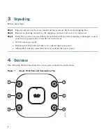
Page 4: ...e received the items listed below If any item is missing or damaged contact your Cisco representative or reseller for instructions 1260 series access point Mounting bracket selected when you ordered the access point Adjustable T rail clip selected when you ordered the access point 4 Overview The following illustrations show the access point connections and features Figure 1 Access Point Ports and ...

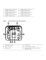
Page 5: ...na connector C labelled with black text 5 5 GHz antenna connector C labelled with blue text 3 2 4 GHz antenna connector A labelled with black text 6 5 GHz antenna connector B labelled with blue text 1 Kensington lock slot 4 Console port 2 Power connection 5 Security padlock and hasp 3 Ethernet port 6 Mounting bracket pins feet for desk or table top mount 272377 2 3 4 1 5 6 6 ...

Page 6: ...ovided by the controller does not change except for customers who have Layer 2 deployments which CAPWAP does not support In a CAPWAP environment a wireless access point discovers a controller by using CAPWAP discovery mechanisms and then sends it a CAPWAP join request The controller sends the access point a CAPWAP join response allowing the access point to join the controller When the access point...

Page 7: ...ain name server DNS For the access point to do so you must configure your DNS to return controller IP addresses in response to CISCO LWAPP CONTROLLER localdomain where localdomain is the access point domain name Configuring the CISCO LWAPP CONTROLLER provides backwards compatibility in an existing customer deployment When an access point receives an IP address and DNS information from a DHCP serve...

Page 8: ...ional Mounting the access point Grounding the access point Deploying the access point on the wireless network Performing a Pre Installation Configuration The following procedures ensure that your access point installation and initial operation go as expected A pre installation configuration is also known as priming the access point This procedure is optional Note Performing a pre installation conf...

Page 9: ...N controller guide a Make sure that access points have Layer 3 connectivity to the Cisco wireless LAN controller Management and AP Manager Interface b Configure the switch to which your access point is to attach See Deploying Cisco 440X Series Wireless LAN Controllers for additional information c Set the Cisco wireless LAN controller as the master so that new access points always join with it d Ma...

Page 10: ...and 3660 multiservice platforms 3725 and 3745 multiservice access routers 3825 and 3845 integrated services routers The recommended external power supply for the access point is the Cisco AIR PWR B power supply The access point can also be powered by the following optional external power sources Any 802 3af compliant power injector Note The 1260 series access point requires a Gigibit Ethernet link...

Page 11: ...n at which you intend to deploy it on the wireless network Step 5 If your access point does not indicate normal operation turn it off and repeat the pre installation configuration Note When you are installing a Layer 3 access point on a different subnet than the Cisco wireless LAN controller be sure that a DHCP server is reachable from the subnet on which you will be installing the access point an...

Page 12: ...ole in Radio Network Optimize Radio Network For Aironet Extensions Configuring Security Settings After you assign basic settings to your access point you must configure security settings to prevent unauthorized access to your network Because it is a radio device the access point can communicate beyond the physical boundaries of your work site Basic security settings are explained in the Configurin...

Page 13: ...13 Note The 802 11n radio only supports no encryption WPA2 Enterprise and WPA 2 Personal WPA 2 Enterprise and WPA 2 Personal requires AES encryption ...

Page 14: ...he access point has joined a controller the LED is green if no clients are associated or blue if one or more clients are associated b If the LED is not on the access point is most likely not receiving power c If the LED blinks sequentially for more than 5 minutes the access point is unable to find its primary secondary and tertiary Cisco wireless LAN controller Check the connection between the acc...

Page 15: ...eless Domain Services WDS and cannot communicate with WDS devices However the controller provides functionality equivalent to WDS when the access point joins it CAPWAP does not support Layer 2 The access point must get an IP address and discover the controller using Layer 3 DHCP DNS or IP subnet broadcast The access point console port is enabled for monitoring and debug purposes all configuration ...

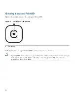
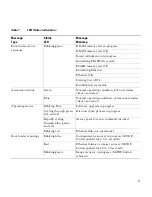
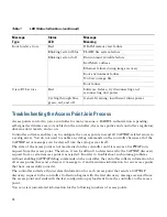
Page 16: ...ion Table 1 shows the access point Status LED indications for various conditions Note Regarding LED status colors it is expected that there will be small variations in color intensity and hue from unit to unit This is within the normal range of the LED manufacturer s specifications and is not a defect 1 Status LED 272378 1 ...

Page 17: ...ss client associated Blue Normal operating condition at least one wireless client association Operating status Blinking blue Software upgrade in progress Cycling through green red and off Discovery join process in progress Rapidly cycling through blue green and red Access point location command invoked Blinking red Ethernet link not operational Boot loader warnings Blinking blue Configuration reco...

Page 18: ... the controller the controller collects information for all access points that send a discovery message to it and maintains information for any access points that have successfully joined it The controller collects all join related information for each access point that sends a CAPWAP discovery request to the controller Collection begins with the first discovery message received from the access po...

Page 19: ...essages to this IP address until it is overridden by one of the following scenarios The access point is still connected to the same controller and the global syslog server IP address configuration on the controller has been changed using the config ap syslog host global syslog_server_IP_address command In this case the controller sends the new global syslog server IP address to the access point Th...

Page 20: ...erence received including interference that may cause undesired operation This equipment has been tested and found to comply with the limits of a Class B digital device pursuant to Part 15 of the FCC Rules These limits are designed to provide reasonable protection against harmful interference when the equipment is operated in a residential environment This equipment generates uses and radiates rad...

Page 21: ...ates on a non interference basis with other devices operating at this frequency when using the integrated antennas Any changes or modification to the product not expressly approved by Cisco could void the user s authority to operate this device Caution Within the 5 15 to 5 25 GHz and 5 47 5 725 GHz bands this device is restricted to indoor operations to reduce any potential for harmful interferenc...

Page 22: ...remises radio stations and unlicensed specified low power radio stations used in factory production lines 1 Before using this equipment make sure that no premises radio stations or specified low power radio stations of RF ID are used in the vicinity 2 If this equipment causes RF interference to a premises radio station of RF ID promptly change the frequency or stop using the device contact the num...

Page 23: ...fied by Electrical Appliance and Material Safety Law that have PSE shown on the code is not limited to CISCO designated products Industry Canada Canadian Compliance Statement This Class B Digital apparatus meets all the requirements of the Canadian Interference Causing Equipment Regulations Cet appareil numerique de la classe B respecte les exigences du Reglement sur le material broilleur du Canad...

Page 24: ...cal Industry Canada office This device has been designed to operate with antennas having a maximum gain of 6 dBi Antennas having a gain greater than 6 dBi are strictly prohibited for use with this device The required antenna impedance is 50 ohms To reduce potential radio interference to other users the antenna type and its gain should be so chosen that the equivalent isotropically radiated power E...

Page 25: ...25 Declaration of Conformity with regard to the R TTE Directive 1999 5 EC Medical Directive 93 42 EEC ...

Page 26: ...EN 301 489 1 v1 4 1 EN 301 489 17 v1 2 1 Health Safety EN60950 1 2001 EN 50385 2002 Radio EN 300 328 v 1 7 1 EN 301 893 v 1 5 1 The conformity assessment procedure referred to in Article 10 4 and Annex III of Directive 1999 5 EC has been followed ...

Page 27: ... inches 20cm to maintain compliance Canada This system has been evaluated for RF exposure for Humans in reference to ANSI C 95 1 American National Standards Institute limits The evaluation was based on RSS 102 Rev 2 The minimum separation distance from the antenna to general bystander is 7 9 inches 20cm to maintain compliance European Union This system has been evaluated for RF exposure for Humans...

Page 28: ...ission on Non Ionizing Radiation Protection limits The minimum separation distance from the antenna to general bystander is 20cm 7 9 inches Administrative Rules for Cisco Aironet Access Points in Taiwan This section provides administrative rules for operating Cisco Aironet access points in Taiwan The rules for all access points are provided in both Chinese and English Chinese Translation ...

Page 29: ...l interference is caused to aviation safety and authorized radio station and if interference is caused the user must stop operating the device immediately and can t re operate it until the harmful interference is clear The authorized radio station means a radio communication service operating in accordance with the Communication Act The operation of the low power radio frequency devices is subject...

Page 30: ...mation Infrastructure 4 7 5 Within the 5 25 5 35 GHz band U NII devices will be restricted to indoor operations to reduce any potential for harmful interference to co channel MSS operations 4 7 6 The U NII devices shall accept any interference from legal communications and shall not interfere the legal communications If interference is caused the user must stop operating the device immediately and...

Page 31: ...kind This equipment may not cause harmful interference to systems operating on a primary basis Declaration of Conformity Statements All the Declaration of Conformity statements related to this product can be found at the following location http www ciscofax com 11 Configuring DHCP Option 43 and DHCP Option 60 This section contains a DHCP Option 43 configuration example on a Windows 2003 Enterprise...

Page 32: ...co IOS CLI Step 2 Create the DHCP pool including the necessary parameters such as default router and name server A DHCP scope example is as follows ip dhcp pool pool name network IP Network Netmask default router Default router dns server DNS Server Where pool name is the name of the DHCP pool such as AP1260 IP Network is the network IP address where the controller resides such as 10 0 15 1 Netmas...

Page 33: ...r the 1260 series access point Table 2 Access Point Specifications Category Specification Dimensions LxWxD 8 68 x 8 68 x 1 84 in 22 04 x 22 04 x 4 67 cm Weight 1 9 lbs 0 86 kg Operating temperature 4 to 131 degrees F 20 to 55 degrees C Storage temperature 22 to 185 degrees F 30 to 85 degrees C Humidity 10 to 90 noncondensing Antenna Diversity system with RP TNC connectors for external antennas Com...

Page 34: ...e Cisco Logo are trademarks of Cisco Systems Inc and or its affiliates in the U S and other countries A listing of Cisco s trademarks can be found at www cisco com go trademarks Third party trademarks mentioned are the property of their respective owners The use of the word partner does not imply a partnership relationship between Cisco and any other company 1005R 2010 Cisco Systems Inc All rights...

Reviews: