background image

3

Rack-Mount the Router

22061

Cisco 7100

 SERIES

22062

0

2

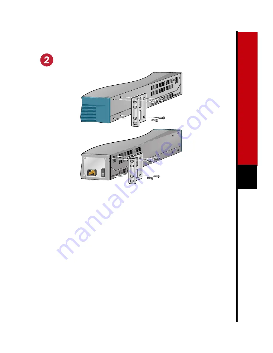
Attach the Brackets to the
Router

1

Locate the brackets and screws.

2

Use a Phillips screwdriver to attach the
brackets on the side panels of the router
in one of the following ways:

— Front panel forward

— Rear panel forward

Note: Although these installations show
the 19-inch brackets, the procedure is the
same for the larger brackets.

Note: This procedure assumes you are
installing the router in a rack. For tabletop
installation, refer to the 
Cisco 7100 Series
VPN Router Installation and Configuration
Guide.

Summary of Contents for 7100 Series

Page 1: ...PREPARE FOR INSTALLATION RACK MOUNT THE ROUTER CONNECT THE ROUTER TO THE NETWORK CONNECT THE POWER START THE SYSTEM 1 2 3 4 5 Quick Start Guide CISCO 7100 SERIES VPN ROUTER 18481 Cisco 7100SERIES ...

Page 2: ......

Page 3: ...rity and is controlled by the authority responsible for the location 1 Ensure the site is set up properly and ensure your safety when installing the router Lift the router safely out of the packing container Ensure the power service at the site is suitable for the router you are installing 2 Check the packing slip to ensure that all the proper components are present 3 Verify that you have the requ...

Page 4: ...imately 0 27 inch 6 858 mm The wire s length is dependent on your router location and site environment This wire is not available from Cisco Systems it is available from any commercial cable vendor Crimping tool large enough to accommodate the diameter of the wire receptacle on your grounding lug Wire stripper Prepare for Installation continued ...

Page 5: ...the side panels of the router in one of the following ways Front panel forward Rear panel forward Note Although these installations show the 19 inch brackets the procedure is the same for the larger brackets Note This procedure assumes you are installing the router in a rack For tabletop installation refer to the Cisco 7100 Series VPN Router Installation and Configuration Guide ...

Page 6: ...to the equipment rack 3 Align the bracket holes with the mounting holes in the equipment rack 4 Use a Phillips screwdriver to attach the router to the equipment rack Warning Do not touch the power supply when the power cord is connected For systems with a power switch line voltages are present within the power supply even when the power switch is off and the power cord is connected For systems wit...

Page 7: ... the 6 AWG wire into the wire receptacle on the grounding lug 4 Use the crimping tool to carefully crimp the wire receptacle around the wire this step is required to ensure a proper mechanical connection 5 Insert the two screws through the holes in the grounding lug Ensure that the grounding lug does not interfere with other router hardware 6 Use a Phillips screwdriver to carefully tighten the scr...

Page 8: ...e Fast Ethernet Ports The 10BaseT 100BaseTX Fast Ethernet ports support IEEE 802 3 and IEEE 802 3u specifications for 10 Mbps and 100 Mbps transmission over unshielded twisted pair UTP cables These ports support autosensing and autonegotiation of the proper transmission mode with an attached device Note Unless noted otherwise all procedures apply to any Cisco 7100 series router 1 Attach a standard...

Page 9: ...ur T1 ports operate at T1 1 544 Mbps and E1 2 048 Mbps speeds Each port uses an identical 60 pin D shell receptacle that supports the following interface types EIA TIA 232 V 35 EIA TIA 449 X 21 EIA 530 1 Attach the appropriate serial cable directly to the receptacle on the router and tighten the strain relief screws 2 Attach the network end of the serial cable to a DSU CSU DTE or other external sy...

Page 10: ...o EIA TIA 612 and EIA TIA 613 specifications The T3 serial ports on the router are considered to be DTE devices Note The T3 ports support several types of integrated DSUs For a listing of DSU feature compatibilities refer to Appendix C Cable Specifications in the Cisco 7100 Series VPN Router Installation and Configuration Guide 1 Attach the appropriate 75 ohm coaxial cable directly to the receptac...

Page 11: ...e E3 serial ports on the router are considered to be DTE devices Note The E3 ports support several types of integrated DSUs For a listing of DSU feature compatibilities refer to Appendix C Cable Specifications in the Cisco 7100 Series VPN Router Installation and Configuration Guide 1 Attach the appropriate 75 ohm coaxial cable directly to the receptacle on the router and tighten the strain relief ...

Page 12: ... at E3 34 Mbps speeds Use a 75 ohm coaxial cable to connect to a T3 or E3 ATM serial network Serial cables conform to EIA TIA 612 and EIA TIA 613 specifications The T3 and E3 serial ports on the router are considered to be DTE devices 1 Attach a 75 ohm coaxial cable directly to the receptacle on the router 2 Attach the network end of the cable to the external synchronous serial equipment Note The ...

Page 13: ...ectors Warning Class 1 laser product Warning Because invisible laser radiation may be emitted from the aperature of the port when no fiber cable is connected avoid exposure to laser radiation and do not stare into open apertures 1 Attach the fiber optic cable either one duplex SC type connector or two simplex SC type connectors directly to the receptacle on the router 2 Attach the network end of t...

Page 14: ...terminal or PC terminal emulation software for 9600 baud 8 data bits no parity and 2 stop bits Note Refer to the Connecting the Console Port and Auxiliary Port section in Chapter 3 Installing Cisco 7100 Series Routers in the Cisco 7100 Series VPN Router Installation and Configuration Guide AC OK DC OK OTF AC OK DC OK OTF RX TX E3 RX 5 TX E3 RX EN CEL CAR ALM I CONS FE 0 0 FE ACT 0 1 AUX 0 2 7140 2...

Page 15: ...ce of a suitably installed ground conductor Contact the appropriate electrical inspection authority or an electrician if you are uncertain that suitable grounding is available Warning The AC power supply has double pole neutral fusing Warning The plug socket combination must be accessible at all times because it serves as the main disconnecting device 1 At the rear of the router check that the pow...

Page 16: ...le retention clip up away from the AC receptacle and plug in the power cable 3 Secure the cable in the power supply AC receptacle by sliding the cable retention clip down until it fits around the connector The cable retention clip provides strain relief for the AC power cable 4 Plug the AC power supply cable into the AC power source Note For full redundancy plug the second AC power cord into a sep...

Page 17: ...n power LED on the router goes on 2 Listen for the fans you should immediately hear them operating 3 During the boot process observe the system LEDs The LEDs on most of the fixed interfaces and port adapters go on and off in irregular sequence 4 Observe the initialization process When the system boot is complete a few seconds the network processor begins to initialize the interfaces During this in...

Page 18: ... system banner similar to the following When you see this information you have successfully booted your router Restricted Rights Legend Use duplication or disclosure by the Government is subject to restrictions as set forth in subparagraph c of the Commercial Computer Software Restricted Rights clause at FAR sec 52 227 19 and subparagraph c 1 ii of the Rights in Technical Data and Computer Softwar...

Page 19: ...brackets Basic management setup configures only enough connectivity for management of the system extended setup will ask you to configure each interface on the system 3 Enter yes or press Return to see the current interface summary First would you like to see the current interface summary yes yes Any interface listed with OK value NO does not have a valid configuration Interface IP Address OK Meth...

Page 20: ...o Configure SNMP Network Management yes no Note The Simple Network Management Protocol SNMP is the most widely supported open standard for network management It provides a means to access and set configuration and run time parameters of routers and communication servers SNMP defines a set of functions that can be used to monitor and control network elements 6 Enter yes or press Return to configure...

Page 21: ...LED descriptions in Chaper 1 Cisco 7100 Series VPN Router Product Overview in the Cisco 7100 Series VPN Router Installation and Configuration Guide to check the status of the interfaces 8 Configure the ATM port in slot 1 Use your own addresses and subnet mask at the setup prompts Consult with your network administrator for this information Do you want to configure ATM1 0 interface yes yes Configur...

Page 22: ...1 enable password betty line vty 0 4 password fred no snmp server ip routing no clns routing interface FastEthernet0 0 media type 100BaseX full duplex ip address 10 1 1 20 255 0 0 0 interface FastEthernet0 1 shutdown no ip address interface ATM1 0 ip address 10 1 1 10 255 0 0 0 interface ATM2 0 shutdown no ip address router igrp 15 redistribute connected network 1 0 0 0 end ...

Page 23: ...ion in the Cisco 7100 Series VPN Router Installation and Configuration Guide for troubleshooting recommendations and procedures For More Information For information on additional interface configuration and specific system configurations see the following publications Cisco 7100 Series VPN Configuration Guide that shipped with your router This document contains sample configurations Cisco 7100 Ser...

Page 24: ...e Slovakia Slovenia South Africa Spain Sweden Switzerland Taiwan Thailand Turkey Ukraine United Kingdom United States Venezuela Access Registrar AccessPath Any to Any AtmDirector CCDA CCDE CCDP CCIE CCNA CCNP CCSI CD PAC the Cisco logo Cisco Certified Internetwork Expert logo CiscoLink the Cisco Management Connection logo the Cisco NetWorks logo the Cisco Powered Network logo Cisco Systems Capital...

Reviews: