2-14
Cisco 6160 Hardware Installation Guide
OL-2190-02 B0
Chapter 2 Preparing for Installation
Site Requirements
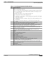
The typical power required for your Cisco 6160 system will depend on your configuration type. Use
to calculate the power required for each of the Cisco 6160 system components and the total
power required for the system.
Warning
Only a DC power source that is isolated from AC mains with reinforced insulation, and that complies
with the other safety extra-low voltage (SELV) requirements in UL1950, CSA 950 3rd Edition, EN 60950,
and IEC950, can be connected to a Cisco 6160 system. This requirement ensures that in a catastrophic
power source fault condition, hazardous voltages are not present on power terminals and connectors.
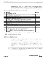
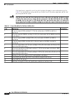
Table 2-3
Power Calculation for the Cisco 6160 System
Step
Instructions
Calculation
1
If you are using 8xIDSLs, multiply 5.5W by the total number of 8xIDSLs installed in
the chassis.
2
If you are using 8xG.SHDSLs, multiply 16.5W by the total number of 8xG.SHDSLs installed
in the chassis.
3
If you are using 8xDMTs, multiply 24W by the total number of 8xDMTs installed in
the chassis.
4
If you are using 4xSDSLs, multiply 9W by the total number of 4xSDSLs installed in
the chassis.
5
If you are using 4xflexis in G.lite mode, multiply 13W by the total number of 4xflexis (G.lite
mode) installed in the chassis.
6
If you are using 4xflexis in DMT mode, multiply 17.5W by the total number of 4xflexis (DMT
mode) installed in the chassis.
7
If you are using 4xflexis in CAP mode, multiply 13.5W by the total number of 4xflexis (CAP
mode) installed in the chassis.
8
Multiply 33.5W by the number of NI-2 cards installed in the chassis.
9
Enter 60W for the PEM. Add 6W if a second PEM is installed in the chassis.
10
Enter 104W for the fan tray.
11
Add lines 1 through 10. This is the typical power required for the Cisco 6160.

