background image

C-3

Cisco ASA 5500 Series Hardware Installation Guide

OL-10089-01

Appendix C      Cable Pinouts

  RJ-45 to DB-9

Examine the sequence of colored wires to determine the type of RJ-45 cable, as follows:

Straight-through—The colored wires are in the same sequence at both ends of the cable. 

Crossover—The first (far left) colored wire at one end of the cable is the third colored wire at the 
other end of the cable.


RJ-45 to DB-9 

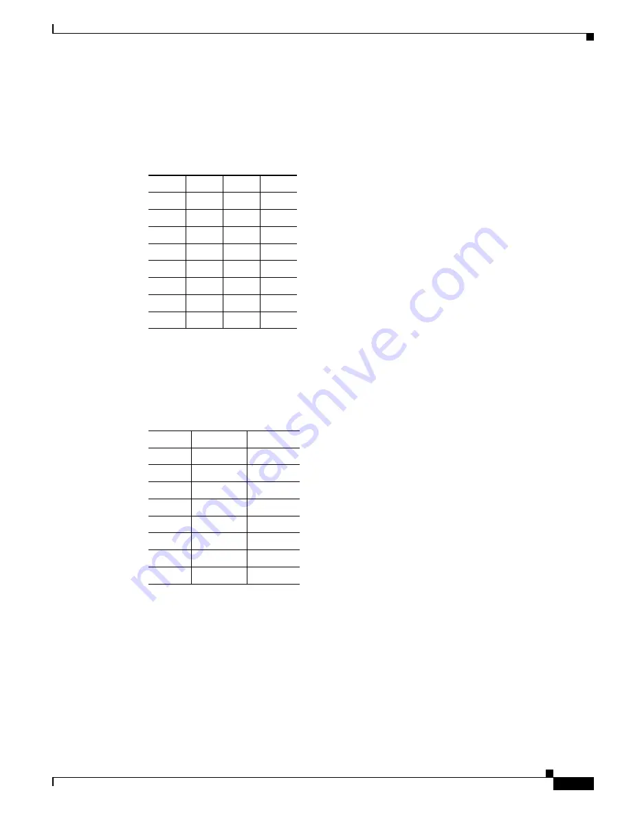
Table C-2

 lists the cable pinouts for RJ-45 to DB-9 or DB-25.

MGMT 10/100/1000 Ethernet Port 

The MGMT 10/100/1000 Ethernet port is an Ethernet port with an RJ-45 connector. You can use a 
modular, RJ-45, straight-through UTP cable to connect the management port to an external hub, switch, 
or router.

Table C-3

 lists the cable pinouts for 10/100/1000BASE-T Management Port Cable Pinouts (MDI).

Table C-1

RJ-45 Rolled (Console) Cable Pinouts 

Signal Pin

Pin

Pin

-

1

8

-

-

2

7

-

-

3

6

-

-

4

5

-

-

5

4

-

-

6

3

-

-

7

2

-

-

8

1

-

Table C-2

Cable Pinouts for RJ-45 to DB-9 or DB-25

Signal 

RJ-45 Pin

DB-9 Pin

RTS

8

8

DTR

7

6

TxD

6

2

GND

5

5

GND

4

5

RxD

3

3

DSR

2

4

CTS

1

7

Summary of Contents for 5505 - ASA Firewall Edition Bundle

Page 1: ...nuals Other 7 I prefer this access method Cisco com CD ROM Printed manuals Other 8 I use the following three product features the most Document Information Document Title Cisco ASA 5500 Series Hardware Installation Guide Part Number OL 10089 01 S W Release if applicable On a scale of 1 5 5 being the best please let us know how we rate in the following areas The document is complete The information...

Page 2: ... L A S S M A I L P E R M I T N O 4 6 3 1 S A N J O S E C A POSTAGE WILL BE PAID BY ADDRESSEE NO POSTAGE NECESSARY IF MAILED IN THE UNITED STATES DOCUMENT RESOURCE CONNECTION CISCO SYSTEMS INC 170 WEST TASMAN DR SAN JOSE CA 95134 9916 ...

Page 3: ...ystems Inc 170 West Tasman Drive San Jose CA 95134 1706 USA http www cisco com Tel 408 526 4000 800 553 NETS 6387 Fax 408 526 4100 Cisco ASA 5500 Series Hardware Installation Guide Customer Order Number Text Part Number OL 10089 01 ...

Page 4: ...erference by using one or more of the following measures Turn the television or radio antenna until the interference stops Move the equipment to one side or the other of the television or radio Move the equipment farther away from the television or radio Plug the equipment into an outlet that is on a different circuit from the television or radio That is make certain the equipment and the televisi...

Page 5: ...y Overview xv Reporting Security Problems in Cisco Products xv Obtaining Technical Assistance xvi Cisco Technical Support Website xvi Submitting a Service Request xvi Definitions of Service Request Severity xvii Obtaining Additional Publications and Information xvii C H A P T E R 1 Preparing for Installation 1 1 Overview 1 1 Installation Overview 1 2 Safety Recommendations 1 2 Maintaining Safety w...

Page 6: ...3 8 A P P E N D I X A Installing and Replacing the SSM A 1 Installing and Replacing the 4GE SSM A 1 Overview A 2 Installing the 4GE SSM A 3 Replacing the 4GE SSM A 4 Installing and Removing the SFP Modules A 4 SFP Module A 5 Installing the SFP Module A 6 Removing the SFP Module A 7 Installing and Replacing the SSM A 8 Installing an SSM A 9 Replacing an SSM A 10 A P P E N D I X B Maintenance and Up...

Page 7: ...the System CompactFlash B 10 Replacing the System CompactFlash B 12 Removing the User CompactFlash B 13 Replacing the User CompactFlash B 14 A P P E N D I X C Cable Pinouts C 1 10 100 1000BaseT Connectors C 1 Console Port RJ 45 C 2 RJ 45 to DB 9 C 3 MGMT 10 100 1000 Ethernet Port C 3 Gigabit and Fibre Channel Ports C 4 I N D E X ...

Page 8: ...Contents iv Cisco ASA 5500 Series Hardware Installation Guide OL 10089 01 ...

Page 9: ...entation Feedback page xv Cisco Product Security Overview page xv Obtaining Technical Assistance page xvi Obtaining Additional Publications and Information page xvii Document Objectives This guide describes how to install hardware components in the following Cisco ASA 5500 series adaptive security appliances Audience This guide is for network administrators who perform any of the following tasks M...

Page 10: ...dix C Cable Pinouts describes the cable pinouts Document Conventions Command descriptions use these conventions Braces indicate a required choice Square brackets indicate optional elements Vertical bars separate alternative mutually exclusive elements Boldface indicates commands and keywords that are entered literally as shown Italics indicate arguments for which you supply values Examples use the...

Page 11: ...aaraa Olet tilanteessa joka voi johtaa ruumiinvammaan Ennen kuin työskentelet minkään laitteiston parissa ota selvää sähkökytkentöihin liittyvistä vaaroista ja tavanomaisista onnettomuuksien ehkäisykeinoista Tässä asiakirjassa esitettyjen varoitusten käännökset löydät laitteen mukana toimitetuista ohjeista Huomautus SÄILYTÄ NÄMÄ OHJEET Attention IMPORTANTES INFORMATIONS DE SÉCURITÉ Ce symbole d av...

Page 12: ...r å unngå ulykker For å se oversettelser av advarslene i denne publikasjonen se de oversatte sikkerhetsvarslene som følger med denne enheten Merk TA VARE PÅ DISSE INSTRUKSJONENE Aviso INSTRUÇÕES IMPORTANTES DE SEGURANÇA Este símbolo de aviso significa perigo O utilizador encontra se numa situação que poderá ser causadora de lesões corporais Antes de iniciar a utilização de qualquer equipamento ten...

Page 13: ...nner dig i en situation som kan leda till personskada Innan du utför arbete på någon utrustning måste du vara medveten om farorna med elkretsar och känna till vanliga förfaranden för att förebygga olyckor Se översättningarna av de varningsmeddelanden som finns i denna publikation och se de översatta säkerhetsvarningarna som medföljer denna anordning OBS SPARA DESSA ANVISNINGAR ...

Page 14: ...page xii Product Disposal Warning page xii Short Circuit Protection Warning page xii Compliance with Local and National Electrical Codes Warning page xii DC Power Connection Warning page xii AC Power Disconnection Warning page xii TN Power Warning page xii 48 VDC Power System page xiii Multiple Power Cord page xiii Circuit Breaker 15A Warning page xiii Grounded Equipment Warning page xiii Safety C...

Page 15: ...e rack When mounting this unit in a partially filled rack load the rack from the bottom to the top with the heaviest component at the bottom of the rack If the rack is provided with stabilizing devices install the stabilizers before mounting or servicing the unit in the rack Statement 1006 Short Circuit Protection Warning Warning This product requires short circuit overcurrent protection to be pro...

Page 16: ...ions Statement 1040 Short Circuit Protection Warning Warning This product requires short circuit overcurrent protection to be provided as part of the building installation Install only in accordance with national and local wiring regulations Statement 1045 Compliance with Local and National Electrical Codes Warning Warning Installation of the equipment must comply with local and national electrica...

Page 17: ... Statement 39 Safety Cover Requirement Warning The safety cover is an integral part of the product Do not operate the unit without the safety cover installed Operating the unit without the cover in place will invalidate the safety approvals and pose a risk of fire and electrical hazards Statement 117 Faceplates and Cover Panel Requirement Warning Blank faceplates and cover panels serve three impor...

Page 18: ...product The Documentation DVD is updated regularly and may be more current than printed documentation The Documentation DVD package is available as a single unit Registered Cisco com users Cisco direct customers can order a Cisco Documentation DVD product number DOC DOCDVD from the Ordering tool or Cisco Marketplace Cisco Ordering tool http www cisco com en US partner ordering Cisco Marketplace ht...

Page 19: ...is URL http www cisco com go psirt If you prefer to see advisories and notices as they are updated in real time you can access a Product Security Incident Response Team Really Simple Syndication PSIRT RSS feed from this URL http www cisco com en US products products_psirt_rss_feed html Reporting Security Problems in Cisco Products Cisco is committed to delivering secure products We test our produc...

Page 20: ...ce You can access the CPI tool from the Cisco Technical Support Website by clicking the Tools Resources link under Documentation Tools Choose Cisco Product Identification Tool from the Alphabetical Index drop down list or click the Cisco Product Identification Tool link under Alerts RMAs The CPI tool offers three search options by product ID or model name by tree view or for certain products by co...

Page 21: ...esources during normal business hours to restore service to satisfactory levels Severity 4 S4 You require information or assistance with Cisco product capabilities installation or configuration There is little or no effect on your business operations Obtaining Additional Publications and Information Information about Cisco products technologies and network solutions is available from various onlin...

Page 22: ...help solve them using real world case studies and business strategies to help readers make sound technology investment decisions You can access iQ Magazine at this URL http www cisco com go iqmagazine Internet Protocol Journal is a quarterly journal published by Cisco Systems for engineering professionals involved in designing developing and operating public and private internets and intranets You...

Page 23: ...1 2 General Site Requirements page 1 4 Overview The adaptive security appliance delivers unprecedented levels of defense against threats to the network with deeper web inspection and flow specific analysis improved secure connectivity via end point security posture validation and voice and video over VPN support It also provides enhanced support for intelligent information networks through improve...

Page 24: ...elines may not address all potentially hazardous situations in your working environment so be alert and exercise good judgement at all times Note If you need to remove the chassis cover to install a hardware component such as additional memory or an interface card doing so does not affect your Cisco warranty Upgrading the adaptive security appliance does not require any special tools and does not ...

Page 25: ...person needs rescue breathing or external cardiac compressions then take appropriate action Use the adaptive security appliance chassis within its marked electrical ratings and product usage instructions Install the adaptive security appliance in compliance with local and national electrical codes as listed in the Regulatory Compliance and Safety Information for the Cisco ASA 5500 Series document ...

Page 26: ...Configuration page 1 4 Power Supply Considerations page 1 5 Configuring Equipment Racks page 1 5 Site Environment Place the chassis on a desktop or mount it on a rack The location of the chassis and the layout of the equipment rack or wiring room are extremely important for proper system operation Equipment placed too close together inadequate ventilation and inaccessible panels can cause system m...

Page 27: ... grounding facilities to guard against damage from lightning or power surges In a chassis equipped with a DC input power supply use the following guidelines Each DC input power supply requires dedicated 15 amp service For DC power cables it is recommend to use a minimum of 14 AWG wire cable The DC return connection to this system is to remain isolated from the system frame and chassis Configuring ...

Page 28: ...1 6 Cisco ASA 5500 Series Hardware Installation Guide OL 10089 01 Chapter 1 Preparing for Installation General Site Requirements ...

Page 29: ...all replace or service this equipment Statement 49 Caution Read the safety warnings in the Regulatory Compliance and Safety Information for the Cisco ASA 5500 Series and follow proper safety procedures when performing these steps This chapter describes the product memory requirements and installation procedures and includes the following topics Product Overview page 2 2 Memory Requirements page 2 ...

Page 30: ...ower 8 SSC 153644 0 0 1 2 3 4 5 6 7 LINK ACT Power Status Active VPN SSC 100 MBPS 4 7 8 1 2 3 5 6 Cisco ASA 5505 Series Adaptive Security Appliance 1 Power 48VDC 5 Console port 2 SSC slot 6 USB 2 0 interface 3 Network interface LEDs 7 Reset button 4 Network interfaces1 1 Ports 6 and 7 are PoE ports used for devices that can be powered by the network interface IP phones for example They can also be...

Page 31: ...nstall replace or service this equipment Statement 49 Caution Read the safety warnings in the Regulatory Compliance and Safety Information for the Cisco ASA 5500 Series and follow proper safety procedures when performing these steps To connect cables to the ports perform the following steps Step 1 Place the chassis on a flat stable surface Step 2 Before connecting a computer or terminal to the por...

Page 32: ...tch ports that support PoE ports numbered 6 and 7 Step 3 Check the LINK LED to verify that the network devices have basic connectivity to the ASA 5505 on one of the inside ports numbered 0 through 7 When connectivity is established the LINK LED on the front panel of the ASA 5505 lights up solid green Figure 2 3 Connecting Cables to Network Interfaces Step 4 Connect the power cord to the security a...

Page 33: ...inal for 9600 baud 8 data bits no parity and 1 stop bit Figure 2 4 Connecting to the Console Cable Powering on the ASA 5505 To power on the ASA 5505 perform the following steps Step 1 Connect the power supply with the power cable Step 2 Connect the small rectangular connector of the power supply cable to the power connector on the rear Step 3 Connect the AC power connector of the power supply inpu...

Page 34: ... slot that accepts standard desktop cable locks to provide physical security The cable lock is not included To install a cable lock perform the following steps Step 1 Follow the directions from the manufacturer for attaching the other end of the cable for securing the ASA 5505 Step 2 Attach the cable lock to the lock slot on the back panel of the ASA 5505 ...

Page 35: ... Cisco ASA 5500 Series and follow proper safety procedures when performing these steps This chapter describes the product memory requirements and rack mount and installation procedures and includes the following topics Product Overview page 3 2 Memory Requirements page 3 5 Installing the Chassis page 3 5 Note The illustrations in this chapter show the Cisco ASA 5540 adaptive security appliance The...

Page 36: ... Solid VPN tunnel is established 5 Flash Green Solid The CompactFlash is being accessed 119638 POWER STATUS FLASH ACTIVE VPN CISCO ASA 5540 SERIES Adaptive Security Appliance 1 2 3 4 5 1 Management port1 1 The management 0 0 interface is a Fast Ethernet interface designed for management traffic only 6 USB 2 0 interfaces2 2 Not supported at this time 11 VPN LED 2 External CompactFlash slot 7 Networ...

Page 37: ...anagement 0 0 interface is a Fast Ethernet interface designed for management traffic only 18 External CompactFlash slot 3 RJ 45 Speed LED 11 Network interfaces4 4 GigabitEthernet interfaces from right to left GigabitEthernet 0 0 GigabitEthernet 0 1 GigabitEthernet 0 2 and GigabitEthernet 0 3 19 Serial Console port 4 Power LED 12 Power indicator LED 20 Power switch 5 Status LED 13 Status indicator ...

Page 38: ...ate Description 2 7 LINK Green Solid Flashing There is an Ethernet link There is Ethernet activity 3 8 SPEED Off Green Amber 10 MB 100 MB 1000 MB GigE There is no network activity There is network activity at 100 Mbps There is network activity at 1000 Mbps 4 POWER Green On The system has power 5 STATUS Green Green Amber Flashing Solid Solid The system is booting The system booted correctly The sys...

Page 39: ...lizers before mounting or servicing the unit in the rack Statement 1006 The following information can help plan equipment rack installation Allow clearance around the rack for maintenance If the rack contains stabilizing devices install the stabilizers prior to mounting or servicing the unit in the rack When mounting a device in an enclosed rack ensure adequate ventilation Do not overcrowd an encl...

Page 40: ... brackets to the holes as shown in Figure 3 5 After the brackets are secured to the chassis you can rack mount it Figure 3 5 Installing the Right and Left Brackets Step 2 Attach the chassis to the rack using the supplied screws as shown in Figure 3 6 Figure 3 6 Rack Mounting the Chassis To remove the chassis from the rack remove the screws that attach the chassis to the rack and then remove the ch...

Page 41: ...tifying the Rubber Feet Step 2 Place the chassis upside down on a smooth flat surface Step 3 Peel off the rubber feet from the black adhesive strip and press them adhesive side down onto the bottom four corners of the chassis see Figure 3 8 Figure 3 8 Attaching the Rubber Feet Step 4 Place the chassis right side up on a flat smooth secure surface Step 5 Connect the interface cables See the Connect...

Page 42: ...y warnings in the Regulatory Compliance and Safety Information for the Cisco ASA 5500 Series and follow proper safety procedures when performing these steps To connect cables to the ports perform the following steps Step 1 Place the chassis on a flat stable surface or in a rack if you are rack mounting it Step 2 Before connecting a computer or terminal to the ports check to determine the baud rate...

Page 43: ...rface to be a management only interface using the management only command You can also disable management only mode on the management interface For more information about this command see the management only command in the Cisco Security Appliance Command Reference Connect one RJ 45 connector to the Management0 0 port as shown in Figure 3 9 Connect the other end of the Ethernet cable to the manage...

Page 44: ...onnector on one end for the serial port on your computer and the other end is an RJ 45 connector Connect the RJ 45 connector to the Console port on the adaptive security appliance Connect the other end of the cable the DB 9 connector to the console port on your computer Figure 3 10 Connecting to the Console Cable 1 RJ 45 Console port 2 RJ 45 to DB 9 console cable 126982 FLASH CONSOLE AUX P O W E R...

Page 45: ...nnector on one end for the serial port on your computer and the other end is an RJ 45 connector Connect the RJ 45 connector to the auxiliary port labeled AUX on the adaptive security appliance Connect the other end of the cable the DB 9 connector to the serial port on your computer Figure 3 11 Connecting to the AUX Port 1 RJ 45 AUX port 2 RJ 45 to DB 9 console cable 92686 FLASH CONSOLE AUX P O W E...

Page 46: ...cable to your network device such as a router switch or hub Note The 4GE SSM is optional this connection is necessary only if you have installed the 4GE SSM on the adaptive security appliance Figure 3 12 Connecting to the RJ 45 port Note When using the 4GE SSM you can use the same numbered copper ports RJ 45 and the SFP ports at the same time 1 Ethernet ports 2 RJ 45 connector 143147 USB1 MGMT USB...

Page 47: ...he port Remove the optical port plugs from the installed SFP as shown in Figure 3 13 Figure 3 13 Removing the Optical Port Plug Connect the LC connector to the SFP module as shown in Figure 3 14 Figure 3 14 Connecting the LC Connector Connect the other end to your network devices such as routers switches or hubs 1 Optical port plug 2 SFP module 143146 1 ST AT US 2 1 LC connector 2 SFP module USB1 ...

Page 48: ...ent port on the SSM as shown in Figure 3 15 Connect the other end of the RJ 45 cable to your network devices Note SSMs are optional this connection is necessary only if you have installed an SSM on the adaptive security appliance Figure 3 15 Connecting to the Management Port 1 SSM management port 2 RJ 45 to RJ 45 cable 143149 USB1 MGMT USB2 MGMT USB2 POWER STATUS USB1 2 LINK ACT SPEED 1 ...

Page 49: ...net cable to your network device such as a router switch or hub Figure 3 16 Connecting Cables to Network Interfaces Step 4 Connect the power cord to the security appliance and plug the other end to the power source For information on powering on a DC model see the Installing the DC Model section on page B 8 Step 5 Power on the chassis 1 RJ 45 Ethernet ports 2 RJ 45 connector USB2 USB1 LNK SPD 3 LN...

Page 50: ...3 16 Cisco ASA 5500 Series Hardware Installation Guide 78 17374 01 Chapter 3 ASA 5510 ASA 5520 ASA 5540 and ASA 5550 Installing the Chassis ...

Page 51: ... the SFP or the RJ 45 ports and not both ports at one time Both the SFP and the RJ 45 ports can be plugged in but use the media type command in interface configuration mode to set the media type to copper or fiber Gigabit Ethernet For a complete description of the command syntax see the Cisco Security Appliance Command Reference Installing and Replacing the 4GE SSM The 4GE SSM has four 10 100 1000...

Page 52: ...on page A 4 Table A 1 describes the 4GE SSM LEDs 1 RJ 45 ports 5 Status LED 2 RJ 45 Link LED 6 SFP ports 3 RJ 45 Speed LED 7 SFP Link LED 4 Power LED 8 SFP Speed LED 132983 4 1 6 5 7 8 LNK SPD 0 1 2 3 2 3 Cisco SSM 4GE Table A 1 4GE SSM LEDs LED Color State Description 2 7 LINK Green Solid Flashing There is an Ethernet link There is Ethernet activity 3 8 SPEED Off Green Amber 10 MB 100 MB 1000 MB ...

Page 53: ...2 Removing the Screws from the Slot Cover Step 4 Insert the 4GE SSM through the slot opening as shown in Figure A 3 Figure A 3 Inserting the 4GE SSM into the Slot Step 5 Attach the screws to secure the 4GE SSM to the chassis Step 6 Power on the adaptive security appliance Step 7 Check the LEDs If the 4GE SSM is installed properly the STATUS LED flashes during boot up and is solid when operational ...

Page 54: ...e screws to secure the 4GE SSM to the chassis Step 7 Enter the hw mod mod 1 reset command in privileged EXEC mode to reset the 4GE SSM Step 8 Check the LEDs If the 4GE SSM is installed properly the POWER LED is solid green and the STATUS LED is flashing during boot up Step 9 Connect the RJ 45 cable to the port and the other end of the cable to your network devices For more information see the Conn...

Page 55: ...uirements for the adaptive security appliance Note Only SFP modules certified by Cisco are supported on the adaptive security appliance Caution Protect your SFP modules by inserting clean dust plugs into the SFPs after the cables are extracted from them Be sure to clean the optic surfaces of the fiber cables before you plug them back into the optical bores of another SFP module Avoid getting dust ...

Page 56: ...o position as shown in Figure A 4 Figure A 4 Installing an SFP Module Caution Do not remove the optical port plugs from the SFP until you are ready to connect cabling Step 2 Remove the Optical port plug then connect the network cable to the SFP module Step 3 Connect the other end of the cable to your network For more information on connecting the cables see Connecting the Interface Cables section ...

Page 57: ...e laser radiation may be emitted from the aperture of the port when no cable is connected avoid exposure to laser radiation and do not stare into open apertures Statement 70 Caution The latching mechanism used on many SFPs locks the SFP into place when cables are connected Do not pull on the cabling in an attempt to remove the SFP Step 2 Disconnect the SFP latch as shown in Figure A 5 Note SFP mod...

Page 58: ...te the slot at a time Table A 4 lists the memory specifications for the AIP SSM 10 and the AIP SSM 20 For more information on the AIP SSM see the Managing the AIP SSM section in the Cisco Security Appliance Command Line Configuration Guide The CSC SSM runs Content Security and Control software The CSC SSM provides protection against viruses spyware spam and other unwanted traffic For more informat...

Page 59: ...Power off the adaptive security appliance Step 2 Locate the grounding strap from the accessory kit and fasten it to your wrist so that it contacts your bare skin Attach the other end to the chassis Step 3 Remove the two screws as shown in Figure A 7 at the left rear end of the chassis and remove the slot cover 119644 P W R S T A T U S S P E E D L I N K A C T 1 2 3 4 Table A 6 SSM LEDs LED Color St...

Page 60: ...placing an SSM Note The following is only supported on the ASA 5510 ASA 5520 and ASA 5540 To replace an existing SSM perform the following steps Step 1 Enter the hw mod mod 1 shut command in privileged EXEC mode Verify if the module is down by checking the LEDs Step 2 Locate the grounding strap from the accessory kit and fasten it to your wrist so that it contacts your bare skin Attach the other e...

Page 61: ...cure the SSM to the chassis Step 7 Enter the hw mod mod 1 reset command in privileged EXEC mode to reset the SSM Step 8 Check the LEDs If the SSM is installed properly the POWER LED is solid green and the STATUS LED flashes green Step 9 Connect one end of the RJ 45 cable to the port and the other end of the cable to your network devices For more information see Figure 3 15 ...

Page 62: ...A 12 Cisco ASA 5500 Series Hardware Installation Guide 78 17374 01 Appendix A Installing and Replacing the SSM Installing and Replacing the SSM ...

Page 63: ...place the chassis cover from the adaptive security appliance This section includes the following topics Removing the Chassis Cover page B 1 Replacing the Chassis Cover page B 3 Removing the Chassis Cover To remove the chassis cover perform the following steps Note Removing the chassis cover does not affect Cisco warranty Upgrading the adaptive security appliance does not require any special tools ...

Page 64: ...ws from the top of the chassis Figure B 1 Figure B 1 Removing the Top Panel Screws Step 4 Pull the top panel up as shown in Figure B 2 Put the panel in a safe place Figure B 2 Removing the Chassis Cover 119635 POWER STATUS FLASH ACTIVE VPN CISCO ASA 5540 SERIES Adaptive Security Appliance 119636 POWER STATUS FLASH ACTIVE VPN CISCO ASA 5540 SERIES Adaptive Security Appliance ...

Page 65: ...tep 1 Place the chassis on a secure surface with the front panel facing you Step 2 Hold the top panel so the tabs at the rear of the top panel are aligned with the chassis bottom Step 3 Lower the front of the top panel onto the chassis as shown in Figure B 3 Figure B 3 Replacing the Chassis Cover Step 4 Fasten the top panel with the screws you set aside earlier as shown in Figure B 4 Figure B 4 Re...

Page 66: ... wrist strap and cord must operate properly If no wrist strap is available ground yourself by touching the metal part of the chassis Removing and Replacing the Power Supply This section describes how to remove and replace the power supply and includes the following topics Removing the AC Power Supply page B 4 Replacing the AC Power Supply page B 7 Removing the AC Power Supply To remove the AC powe...

Page 67: ...n Figure B 5 Figure B 5 Removing the Power Supply Screws Step 7 Locate the power connector on the system board Step 8 Unlatch the plug then grasp the sides of the power connector and pull upward while rocking the connector from side to side Disconnect the power connector from the system board as shown in Figure B 6 Figure B 6 Disconnecting the Power Connector 1 Chassis bottom 119581 P O W E R FLAS...

Page 68: ...Replacing the Power Supply Step 9 Remove the power supply brace by pulling it up and then out as shown in Figure B 7 Figure B 7 Removing the Power Supply Step 10 From the back of the chassis push the power supply forward and then lift it up and out 1 Back panel 3 Power supply brace 2 Power supply 4 Front panel 119578 3 1 2 4 ...

Page 69: ... Step 2 Lift the rear of the adaptive security appliance from the surface and reinstall both screws Step 3 Insert the power supply brace and press down until it fits into place as shown in Figure B 8 Figure B 8 Replacing the Power Supply Brace and the AC Power Supply Step 4 Connect the power connector to the system board Step 5 Replace the adaptive security appliance cover See Replacing the Chassi...

Page 70: ...perform the following steps Step 1 Read the Regulatory Compliance and Safety Information for the Cisco ASA 5500 Series document Step 2 Terminate the DC input wiring on a DC source capable of supplying at least 15 amps A 15 amp circuit breaker is required at the 48 VDC facility power source An easily accessible disconnect device should be incorporated into the facility wiring Step 3 Locate the DC i...

Page 71: ...ends of the wires for insertion into the power connect lugs on the adaptive security appliance Step 8 Insert the ground wire into the connector for the earth ground and tighten the screw on the connector See Figure B 10 and using the same method as for the ground wire connect the negative wire and then the positive wire Note The DC return connection to this system is to remain isolated from the sy...

Page 72: ...tFlash external This section includes the following topics Removing the System CompactFlash page B 10 Replacing the System CompactFlash page B 12 Removing the User CompactFlash page B 13 Replacing the User CompactFlash page B 14 Removing the System CompactFlash To remove the system CompactFlash perform the following steps Step 1 Power off the adaptive security appliance Step 2 Remove the power cor...

Page 73: ... Step 6 Carefully slide the CompactFlash out of its connector as shown in Figure B 11 The CompactFlash has a lip on its lower edge which you can use to grip the CompactFlash Otherwise use sliding pressure with your thumb or finger to slide the CompactFlash out of its connector Figure B 11 Removing the System CompactFlash 1 System CompactFlash 119580 1 ...

Page 74: ...owing steps Step 1 Align the new system CompactFlash with the connector on the riser card Step 2 Push the system CompactFlash inward until it is fully seated in the connector see Figure B 12 Figure B 12 Replacing the System CompactFlash Step 3 Replace the adaptive security appliance cover See the Replacing the Chassis Cover section on page B 3 for the procedure Step 4 Reinstall the network interfa...

Page 75: ...ocate the user CompactFlash in its slot in the rear panel of the chassis Step 2 Press the release button to eject the card See Figure B 13 Figure B 13 User CompactFlash Slot Release Button Step 3 Carefully pull the card out of the slot Step 4 Place the removed user CompactFlash on an antistatic surface or in a static shielding bag 1 User CompactFlash slot 2 Release button 126990 FLASH CONSOLE AUX ...

Page 76: ... the user CompactFlash slot in the rear panel of the chassis See Figure B 14 Figure B 14 User CompactFlash Slot Step 2 With the label facing up insert the connector end of the user CompactFlash into the slot until the card is seated in the connector and the release button is pushed out Note The user CompactFlash is keyed so that it cannot be inserted wrong 1 User CompactFlash slot 126989 FLASH CON...

Page 77: ...curity appliance supports 10 100 1000BaseT ports You must use at least a Category 5 cable for 100 1000baseT operations but a Category 3 cable can be used for 10BaseT operations The 10 100 1000BaseT ports use standard RJ 45 connectors and supports MDI and MDI X connectors Ethernet ports normally use MDI connectors and Ethernet ports on a hub normally use an MDI X connector Use an Ethernet straight ...

Page 78: ...ote Cisco does not provide these cables they are widely available from other sources Figure C 3 shows the RJ 45 cable Figure C 3 RJ 45 Cable To identify the RJ 45 cable type hold the two ends of the cable next to each other so that you can see the colored wires inside the ends as shown in Figure C 4 Figure C 4 RJ 45 Cable Identification 60915 2 3 1 4 5 6 7 8 Pin Label 1 2 3 4 5 6 7 8 TP0 TP0 TP1 T...

Page 79: ...ble C 2 lists the cable pinouts for RJ 45 to DB 9 or DB 25 MGMT 10 100 1000 Ethernet Port The MGMT 10 100 1000 Ethernet port is an Ethernet port with an RJ 45 connector You can use a modular RJ 45 straight through UTP cable to connect the management port to an external hub switch or router Table C 3 lists the cable pinouts for 10 100 1000BASE T Management Port Cable Pinouts MDI Table C 1 RJ 45 Rol...

Page 80: ...d connectors used in the adaptive security appliance Table C 3 10 100 1000BASE T Management Port Cable Pinouts MDI Signal Pin TD 1 TD 2 RD 3 RD 6 Not used 4 Not used 5 Not used 7 Not used 8 Table C 4 SFP Modules and Connectors Port Compliance Connector Fiber Type Gigabit Ethernet 1000BASE SX SW MMF 1000BASE LX LW SMF Table C 5 SFP Port Cabling Specifications Cisco Product Number Wavelength nanomet...

Page 81: ...sco warranty 1 2 CompactFlash External 3 2 3 3 Internal B 10 B 13 Console port 3 10 CPU 3 5 CSC SSM see SSM A 8 E electrostatic discharge see ESD equipment racks tips 1 5 ESD preventing 1 4 B 4 F fans ventilation 1 5 G grounding lug attaching B 9 I installing 2 3 3 8 L LC connector 3 13 LEDs 3 4 A 2 A 9 M Management Port 3 9 memory requirements 3 5 MGMT 3 2 3 3 3 9 N Network interfaces 3 2 P panel...

Page 82: ...r panels figure 3 4 Removing B 10 RJ 45 connector pinouts C 3 RJ 45 port 3 12 rubber feet attaching 3 7 S safety 1 2 Serial Console port 3 2 3 3 SFP 3 13 A 4 site environment 1 4 SSM 4GE SSM connecting 3 12 installing A 3 LEDs 3 4 A 2 replacing A 4 Intelligent SSM A 8 connecting 3 14 installing A 9 LEDs A 9 replacing A 10 V ventilation fans 1 5 W warranty 1 2 ...

Reviews: