background image

3

Connect the Hub to Other Network Devices 
(continued)

RATING

100-127 / 200-240 V~

2A /1A   50 / 60 Hz

CONSOLE

UP

MEDIA MODULE

DOWN

DC INPUT

DC INPUTS FOR REMOTE

POWER SUPPLY

SPECIFIED IN MANUAL

+5V     

@

6A, +12V     

@

1A

10/100 BASE-TX

STAT DUP 100

RATING

100-127 / 200-240 V~

2A /1A   50 / 60 Hz

CONSOLE

UP

MEDIA MODULE

DOWN

DC INPUT

DC INPUTS FOR REMOTE

POWER SUPPLY

SPECIFIED IN MANUAL

+5V     

@

6A, +12V     

@

1A

10/100 BASE-TX

STAT DUP 100

RATING

100-127 / 200-240 V~

2A /1A   50 / 60 Hz

CONSOLE

UP

MEDIA MODULE

DOWN

DC INPUT

DC INPUTS FOR REMOTE

POWER SUPPLY

SPECIFIED IN MANUAL

+5V     

@

6A, +12V     

@

1A

DUP

LINK

100 BASE-FX

RX

TX

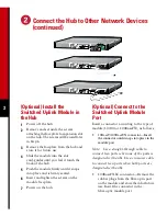
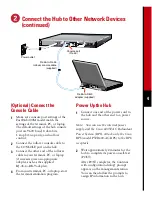
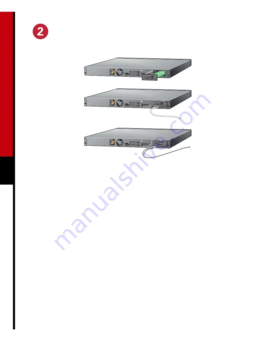
(Optional) Install the 
Switched Uplink Module in 
the Hub

1

Power off the hub.

2

Remove and set aside the screws 
attaching the faceplate to expansion slot 
on the hub. The screws will be used later 
in Step 6.

3

Remove the faceplate from the hub and 
store it for future use.

4

Slide the module into the slot 
card-guides until you feel it touch the 
back of the hub.

5

Push the module firmly until it snaps 
into place and is firmly seated.

6

Insert and tighten the screws on the 
module faceplate.

7

Power on the hub.

(Optional) Connect to the 
Switched Uplink Module 
Port

Insert a connector according to the type of 
module (10/100 or 100BaseFX), as follows:

10BaseT/100BaseTX connector—Insert 
the connector until it snaps into place in the 
module port

.

Note: Use a straight-through cable to 
connect two ports when one of the ports is 
designated with an 

X

. Use a crossover cable 

to connect two ports when both ports are 
designated with an 

X

.

100BaseFX SC connector—Remove the 
rubber plugs from the fiber-optic port 
on the module and store them for future 
use. Insert the connector in the 
fiber-optic module port.

Summary of Contents for 400 Series

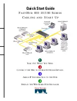
Page 1: ...OUT WHAT YOU NEED CONNECT THE HUB TO OTHER NETWORK DEVICES ASSIGN IP INFORMATION TO THE HUB DISPLAY THE WEB BASED HUB MANAGER 1 2 3 4 Quick Start Guide FASTHUB 400 10 100 SERIES CABLING AND START UP SER IES ...

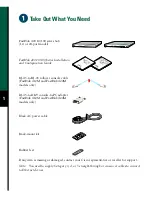
Page 2: ...nd Configuration Guide RJ 45 to RJ 45 rollover console cable FastHub 412M and FastHub 424M models only RJ 45 to DB 9 console to PC adapter FastHub 412M and FastHub 424M models only Black AC power cable Rack mount kit Rubber feet 24 RPS 10 100 MODE 1x 16x 2x 3x 4x 5x 6x 7x 8x 9x 10x 11x 12x 13x 14x 15x 24x 17x 19x 20x 21x 22x 23x 18x 10BaseT 100BaseTx RPS 10 100 MODE 1x 12 10BaseT 100BaseTx 2x 3x 4...

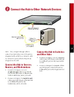
Page 3: ... both ports are designated with an X Connect the Hub to Servers Routers and Workstations Connect a Category 3 4 or 5 straight through cable to any 10 100 port on the hub and to a 10BaseT port on the workstation server or router Connect a Category 5 straight through cable to any 10 100 port on the hub and to a 100BaseTX port on the workstation server or router Connect the Hub to Switches and Other ...

Page 4: ...he hub The screws will be used later in Step 6 3 Remove the faceplate from the hub and store it for future use 4 Slide the module into the slot card guides until you feel it touch the back of the hub 5 Push the module firmly until it snaps into place and is firmly seated 6 Insert and tighten the screws on the module faceplate 7 Power on the hub Optional Connect to the Switched Uplink Module Port I...

Page 5: ...t the rollover console cable to the CONSOLE port on the hub 3 Connect the other end of the rollover cable to your terminal PC or laptop if necessary use an appropriate adapter such as the supplied RJ 45 to DB 9 adapter 4 From your terminal PC or laptop start the terminal emulation program Power Up the Hub 1 Connect one end of the power cord to the hub and the other end to a power source Note You c...

Page 6: ...alog Y 2 Enter the IP address for example 10 1 105 20 Enter IP address 10 1 105 20 3 Enter the subnet mask IP netmask for example 255 255 255 0 Enter IP netmask 255 255 255 0 4 Enter the IP address of the default gateway for example 10 1 105 254 Enter IP default gateway 10 1 105 254 The following information is displayed The following configuration command script was created ip address 10 1 105 20...

Page 7: ... 400 10 100 series Hub Manager online help provide complete information about the web console and describe how to configure and monitor the hub Click Help for procedures and detailed field descriptions Click these topics to move from page to page On Netscape Communicator only when the cursor is above a topic a pop up briefly describes the options on that particular page Click Revert to discard una...

Page 8: ...audi Arabia Scotland Singapore South Africa Spain Sweden Switzerland Taiwan ROC Thailand Turkey United Arab Emirates United States Venezuela AccessPath Any to Any AtmDirector the CCIE logo CD PAC Centri the Cisco Capital logo CiscoLink the Cisco Management Connection logo the Cisco NetWorks logo the Cisco Powered Network logo the Cisco Press logo the Cisco Technologies logo ClickStart ControlStrea...

Reviews: