


5-20
Cisco ONS 15454 Installation and Operations Guide
78-13453-01
Chapter 5 SONET Topologies
Bidirectional Line Switched Rings
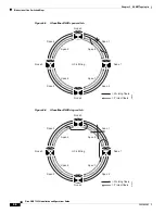
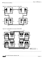
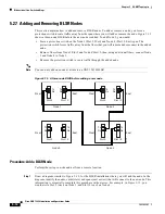
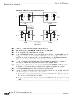
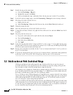
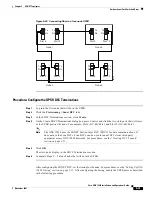
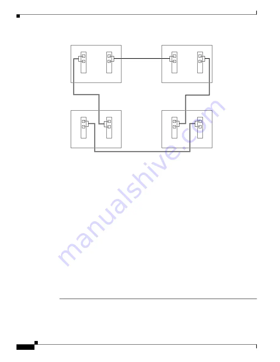
Figure 5-16 A BLSR with a newly-added fourth node
Step 11
Log out of CTC and then log back into any node in the BLSR.
Step 12
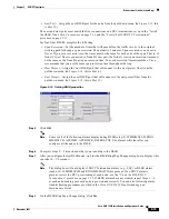
In node view, select the Provisioning > Ring tabs and click Ring Map.
Step 13
On the BLSR Map Ring Change dialog box, click Yes.
Step 14
On the BLSR Ring Map dialog box, verify that the new node is added. If it is, click Accept. If it does
not appear, log into the new node. Verify that the BLSR is provisioned correctly according to the
“Provision the BLSR” procedure on page 5-14
, then repeat Steps 12 – 13. If the node still does not
appear, repeat the steps in the procedure making sure that no errors were made.
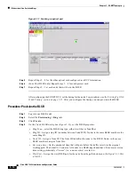
Step 15
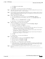
From the Go To menu, select Network View. Click the Circuits tab. Wait until all the circuits are
discovered. The circuits that pass through the new node will be shown as incomplete.
Step 16
In network view, right-click the new node and select Update Circuits With The New Node from the
shortcut menu. Verify that the number of updated circuits displayed in the dialog box is correct.
Step 17
Select the Circuits tab and verify that no incomplete circuits are present.
Step 18
Clear the protection switch for the node that is using its east port to connect to the new node, and for the
node that is using its west port to connect to the new node.
a.
To clear the protection switch from the east port, display the Maintenance > Ring tabs. From the
East Switch list choose CLEAR. Click Apply.
b.
To clear the protection switch from the west port, choose CLEAR from the West Switch list. Click
Apply.
68119
Node 1 Fiber
connected to
Slot 12 (East)
Node 4 Fiber
connected to
Slot 5 (West)
West
East
West
East
West
East
West
East
Slot 5
Tx
Rx
Slot 12
Tx
Rx
Node 3
Slot 5
Tx
Rx
Slot 12
Tx
Rx
Node 2
Node 1
Slot 5
Tx
Rx
Slot 12
Tx
Rx
Node 4
Slot 5
Tx
Rx
Slot 12
Tx
Rx