background image


3-5

Cisco Aironet 1300 Series Wireless Outdoor Access Point/Bridge Hardware Installation Guide

OL-5048-06

Chapter 3      Mounting Overview

LEDs

LEDs

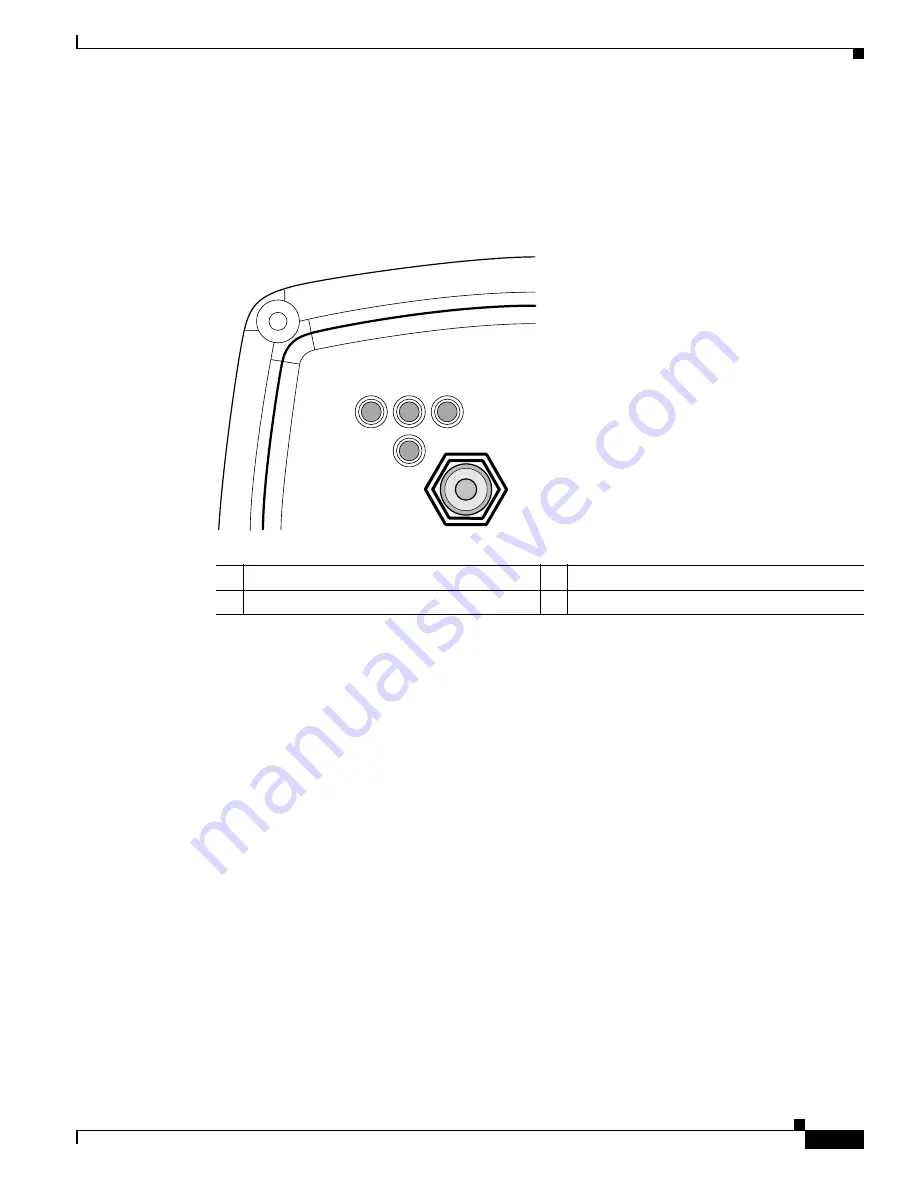
The LEDs indicate the status, radio activity, and Ethernet activity. The LEDs are mounted on the back 
of the housing (see 

Figure 3-2

).

Figure 3-2

LEDs 

For additional information on LED indications, refer to the 

“Troubleshooting Autonomous Access 

Points and Bridges” section on page 4-1

 or the 

“Troubleshooting Lightweight Access Points” section on 

page 5-1

.

Autonomous Access Point/Bridge

When the autonomous access point/bridge running Cisco IOS Release 12.3(4)JA is initially powered-up, 
the unit defaults to a root access point with the radio disabled and no default SSID. To allow client 
associations, you must configure an SSID and enable the radio interface (refer to the 

Cisco IOS Software 

Configuration Guide for Access Points

).

When the autonomous access point/bridge running Cisco IOS Release 12.3(2)JA2 and earlier is initially 
powered-up, the bridge installation mode is activated and the unit attempts to associate to a root bridge 
for 60 seconds. If it is unable to associate with a root bridge, it automatically assumes the root bridge 
role.

R

Radio LED 

E

Ethernet LED 

S

Status LED 

I

Install LED 

117061

R

S

I

E

Summary of Contents for 1310G - Aironet Outdoor Access Point

Page 1: ...est Tasman Drive San Jose CA 95134 1706 USA http www cisco com Tel 408 526 4000 800 553 NETS 6387 Fax 408 526 4100 Cisco Aironet 1300 Series Wireless Outdoor Access Point Bridge Hardware Installation Guide December 2006 Text Part Number OL 5048 06 ...

Page 2: ... or the other of the television or radio Move the equipment farther away from the television or radio Plug the equipment into an outlet that is on a different circuit from the television or radio That is make certain the equipment and the television or radio are on circuits controlled by different circuit breakers or fuses Modifications to this product not authorized by Cisco Systems Inc could voi...

Page 3: ...lems in Cisco Products xiv Product Alerts and Field Notices xiv Obtaining Technical Assistance xv Cisco Support Website xv Locating the Product Serial Number xvi Submitting a Service Request xvii Definitions of Service Request Severity xviii Obtaining Additional Publications and Information xviii C H A P T E R 1 Overview 1 1 Product Terminology 1 1 Autonomous Access Point Bridge 1 1 Lightweight Ac...

Page 4: ... 2 Installation Overview 2 1 Safety Warnings 2 2 All Installations 2 2 Outdoor and DC Power Source Installations 2 3 DC Power Source Installations 2 3 Safety Information 2 3 FCC Safety Compliance Statement 2 3 Safety Precautions 2 4 Typical Outdoor Installation Components 2 5 Installation Guidelines 2 5 Site Surveys 2 6 Unpacking the Access Point Bridge 2 6 Package Contents 2 6 Before Beginning th...

Page 5: ...Using the Web Browser Interface 4 10 Using the CLI on an Autonomous Access Point Bridge 4 10 Reloading the Access Point Bridge Image 4 11 Web Browser Interface 4 11 Browser HTTP Interface 4 11 Browser TFTP Interface 4 12 Obtaining the Autonomous Access Point Bridge Image File 4 13 Obtaining the TFTP Server Software 4 14 C H A P T E R 5 Troubleshooting Lightweight Access Points 5 1 Checking the LED...

Page 6: ...ng Cisco Aironet Access Points and Bridges in Japan B 6 Japanese Translation B 6 English Translation B 7 Administrative Rules for Cisco Aironet Access Points and Bridges in Taiwan B 7 All Access Points and Bridges B 7 Chinese Translation B 7 English Translation B 8 Declaration of Conformity Statements B 8 Declaration of Conformity Statements for European Union Countries B 8 A P P E N D I X C Acces...

Page 7: ...o Aironet 1300 Series Wireless Outdoor Access Point Bridge Hardware Installation Guide OL 5048 06 A P P E N D I X H Load Dump Protection for Transportation Vehicles H 1 Load Dump Protection H 1 G L O S S A R Y I N D E X ...

Page 8: ...Contents viii Cisco Aironet 1300 Series Wireless Outdoor Access Point Bridge Hardware Installation Guide OL 5048 06 ...

Page 9: ...ed information about Cisco IOS commands used with autonomous access points refer to the Cisco IOS Command Reference for Cisco Aironet Access Points and Bridges for this release For information about the standard Cisco IOS Release 12 3 commands refer to the Cisco IOS documentation set available from the Cisco com home page at Technical Support Documentation On the Technical Support Documentation ho...

Page 10: ... regulatory organizations Appendix D Channels and Maximum Power Levels indicates how to access the document that lists the access point bridge radio channels and the maximum power levels supported by the world s regulatory domains Appendix E Console Serial Cable Pinouts identifies the pinouts for the serial cable that connects to the power injector s console serial port Appendix F Priming Lightwei...

Page 11: ... garde figurant dans cette publication veuillez consulter l annexe intitulée Translated Safety Warnings Traduction des avis de sécurité Warnung Dieses Warnsymbol bedeutet Gefahr Sie befinden sich in einer Situation die zu einer Körperverletzung führen könnte Bevor Sie mit der Arbeit an irgendeinem Gerät beginnen seien Sie sich der mit elektrischen Stromkreisen verbundenen Gefahren und der Standard...

Page 12: ...s listed under Wireless LAN Access To browse to controller documentation click Cisco 4400 Series Wireless LAN Controllers or Cisco 2000 Series Wireless LAN Controllers listed under Wireless LAN Controllers Obtaining Documentation Cisco documentation and additional literature are available on Cisco com This section explains the product documentation resources that Cisco offers Cisco com You can acc...

Page 13: ...DOCDVD or DOC DOCDVD SUB from Cisco Marketplace at the Product Documentation Store at this URL http www cisco com go marketplace docstore Ordering Documentation You must be a registered Cisco com user to access Cisco Marketplace Registered users may order Cisco documentation at the Product Documentation Store at this URL http www cisco com go marketplace docstore If you do not have a user ID or pa...

Page 14: ...r conditions are considered nonemergencies For nonemergencies psirt cisco com In an emergency you can also reach PSIRT by telephone 1 877 228 7302 1 408 525 6532 Tip We encourage you to use Pretty Good Privacy PGP or a compatible product for example GnuPG to encrypt any sensitive information that you send to Cisco PSIRT can work with information that has been encrypted with PGP versions 2 x throug...

Page 15: ... com RPF register register do Note Before you submit a request for service online or by phone use the Cisco Product Identification Tool to locate your product serial number You can access this tool from the Cisco Support website by clicking the Get Tools Resources link clicking the All Tools A Z tab and then choosing Cisco Product Identification Tool from the alphabetical list This tool offers thr...

Page 16: ...on Guide OL 5048 06 Preface Obtaining Technical Assistance Locating the Product Serial Number The access point bridge serial number is located on the bottom of the cabinet refer to Figure 1 Figure 1 Location of Access Point Serial Number Label 117062 R S I E SN AAANNNNXXXX SN AAANNNNXXXX ...

Page 17: ...en S3 and S4 service requests S3 and S4 service requests are those in which your network is minimally impaired or for which you require product information After you describe your situation the TAC Service Request Tool provides recommended solutions If your issue is not resolved using the recommended resources your service request is assigned to a Cisco engineer The TAC Service Request Tool is loc...

Page 18: ...nologies and network solutions is available from various online and printed sources The Cisco Online Subscription Center is the website where you can sign up for a variety of Cisco e mail newsletters and other communications Create a profile and then select the subscriptions that you would like to receive To visit the Cisco Online Subscription Center go to this URL http www cisco com offer subscri...

Page 19: ...gies with Cisco experts and other networking professionals Join a discussion at this URL http www cisco com discuss networking What s New in Cisco Documentation is an online publication that provides information about the latest documentation releases for Cisco products Updated monthly this online publication is organized by product category to direct you quickly to the documentation for your prod...

Page 20: ...xx Cisco Aironet 1300 Series Wireless Outdoor Access Point Bridge Hardware Installation Guide OL 5048 06 Preface Obtaining Additional Publications and Information ...

Page 21: ...e autonomous product The term lightweight access point describs only the lightweight product The term access point describes the product when configured to operate as an access point The term bridge describes the product when configured to operate as a bridge Autonomous Access Point Bridge The autonomous access point bridge model AIR BR1310G supports a management system based on Cisco IOS software...

Page 22: ...weight access point and controller do not match After a lightweight access point associates with a controller you can reassign it to any controller on your network LWAPP secures the control communication between the lightweight access point and controller by means of a secure key distribution using X 509 certificates on both the lightweight access point and controller This chapter provides informa...

Page 23: ... Console serial interface on power injector Integrated antenna or external antenna configurations see Figure 1 1 The autonomous access point bridge supports these additional key features Receive Signal Strength Indicator RSSI LED patterns for easy antenna alignment Control using Cisco IOS commands Internet browser SNMP or serial interface Operating modes Root and non root bridge Access point Workg...

Page 24: ...e power injector Dual coax cables are used to provide Ethernet data and power from the power injector to the access point bridge The power injector is an external unit designed for operation in a sheltered environment such as inside a building or vehicle The power injector also functions as an Ethernet repeater by connecting to a Category 5 LAN backbone and using the dual coax cable interface to t...

Page 25: ... RF connectors are provided on the end of the unit to support single or diversity antenna configurations The antennas connect to the access point bridge antenna connectors using a coax cable Table 1 1 lists the external antennas supported by the access point bridge Note To meet regulatory restrictions the external antenna access point bridge unit and the external antenna must be professionally ins...

Page 26: ...efer to Access Point Specifications section on page C 1 Connectors The connectors see Figure 1 2 provided depend upon the access point bridge configuration Integrated antenna access point bridge configuration Dual coax Ethernet connectors used to provide Ethernet signals and in line power External antenna access point bridge configuration Dual coax Ethernet connectors used to provide Ethernet sign...

Page 27: ...The status LED indicates association status Blinking green indicates that the access point bridge is not associated with another bridge Steady green indicates that the unit is associated with at least one other bridge On autonomous access points this LED also provides signal strength readings during installation mode The Ethernet LED indicates Ethernet traffic This LED blinks green when a packet i...

Page 28: ...ss client devices Non Root Bridge Specifies that the unit is operating as a non root bridge that it connects to a remote LAN network and that it must associate with a Cisco Aironet root bridge using the wireless interface Root Bridge with Wireless Clients Specifies that the unit is operating as a root bridge and accepts wireless client associations Non Root Bridge with Wireless Clients Specifies t...

Page 29: ...nge An autonomous access point can be configured as a stand alone repeater to extend the range of your infrastructure or to overcome an obstacle that blocks radio communication The repeater forwards traffic between wireless users and the wired LAN by sending packets to either another repeater or to an access point connected to the wired LAN The data is sent through the route that provides the best...

Page 30: ...s users If more than one autonomous access point is connected to the LAN users can roam from one area of a facility to another without losing their connection to the network As users move out of range of one access point they automatically connect to the network associate through another access point The roaming process is seamless and transparent to the user Figure 1 5 shows access points acting ...

Page 31: ...ll stations together The access point serves as the focal point for communications increasing the communication range of wireless users Figure 1 6 shows an autonomous access point in an all wireless network Figure 1 6 Access Point as Central Unit in All Wireless Network Bridge Network with Wireless Clients The access point supports root bridge and non root bridge roles used to interconnect a remot...

Page 32: ...s classified as a root bridge and the other bridge is classified as a non root bridge Figure 1 8 Point to Point Bridge Configuration Workgroup Bridge Network The access point supports a workgroup bridge role to interconnect remote Ethernet workstations to the main LAN The workgroup bridge can communicate with an access point see Figure 1 9 or with a bridge see Figure 1 10 Figure 1 9 Workgroup Brid...

Page 33: ...3 network operation Lightweight access points and controllers in Layer 3 configurations use IP addresses and UDP packets which can be routed through large networks Layer 3 operation is scalable and recommended by Cisco This section illustrates a typical wireless network configuration containing lightweight access points and a Cisco Wireless LAN Controller see Figure 1 11 Figure 1 11 Typical Lightw...

Page 34: ...1 14 Cisco Aironet 1300 Series Wireless Outdoor Access Point Bridge Hardware Installation Guide OL 5048 06 Chapter 1 Overview Network Examples with Lightweight Access Points ...

Page 35: ...chapter provides warnings safety information and information needed before you begin the installation of your access point bridge system This chapter includes the following sections Safety Warnings page 2 2 Safety Information page 2 3 Unpacking the Access Point Bridge page 2 6 Before Beginning the Installation page 2 7 Installation Summary page 2 9 ...

Page 36: ...5B Warning In order to comply with international radio frequency RF exposure limits dish antennas should be placed at a minimum of 8 7 inches 22 cm from the bodies of all persons Other antennas should be placed a minimum of 7 9 inches 20 cm from the bodies of all persons Statement 346 Warning Do not work on the system or connect or disconnect cables during periods of lightning activity Statement 1...

Page 37: ...sed safety standards Statement 1033 Safety Information Follow the guidelines in this section to ensure proper operation and safe use of the access point bridge FCC Safety Compliance Statement The FCC with its action in ET Docket 96 8 has adopted a safety standard for human exposure to RF electromagnetic energy emitted by FCC certified equipment When used with approved Cisco Aironet antennas Cisco ...

Page 38: ...nience considering your life is at stake 4 Plan your installation carefully and completely before you begin Successful raising of a mast or tower is largely a matter of coordination Each person should be assigned to a specific task and should know what to do and when to do it One person should be in charge of the operation to issue instructions and watch for signs of trouble 5 When installing your...

Page 39: ...e Protection Association NFPA 70 National Electrical Code U S Canadian Electrical Code Part I CSA 22 1 Canada and if local or national electrical codes are not available refer to IEC 364 Part 1 through 7 other countries Note The grounding block is not required for indoor installations of the access point bridge and antenna Installation Guidelines Because the access point bridge is a radio device i...

Page 40: ...interference from other unlicensed radio systems Physical environment Clear or open areas provide better radio range than closed or filled areas Obstructions Physical obstructions such as buildings trees or hills can hinder performance of wireless devices Avoid locating the devices in a location where there is an obstruction between the sending and receiving antennas Unpacking the Access Point Bri...

Page 41: ...d electrical joint compound The optional wall mount kit for indoor use contains these items Wall mount bracket with 4 mounting bolts and washers Two sub mini RG 59 coax cables 12 in or 30 5 cm The optional transportation power injector Power injector LR2T unit Before Beginning the Installation Before you begin the installation process please carefully review the following list of figures to become...

Page 42: ...idge Layout Figure 2 3 Power Injector Indicators and Connectors 1 Grounding studs 4 LEDs 2 Antenna connectors 5 Dual coax Ethernet ports F Type connectors 3 Mounting lugs 117060 1 2 3 4 5 1 Dual coax Ethernet ports F Type connectors 4 Ethernet LAN port RJ 45 connector 2 Power LED 5 Console serial port RJ 45 connector 3 Power jack 117189 C I S C O A I R O N E T P O W E R I N J E C T O R 5 4 1 1 3 2...

Page 43: ...rnal antenna access point bridge unit and the external antenna must be professionally installed The network administrator or other IT professional responsible for installing and configuring the unit is a suitable professional installer Following installation access to the unit should be password protected by the network administrator to maintain regulatory compliance During the installation of the...

Page 44: ... is available Statement 1024 Connect a ground wire to the access point bridge use the ground lug For outdoor installations connect the dual coax Ethernet cables to the grounding block and to the access point bridge For indoor installations connect the dual coax cables directly to the access point bridge Tip You can connect the dual coax cable connectors to either of the grounding block connectors ...

Page 45: ...Point Bridge Hardware Installation Guide OL 5048 06 3 Mounting Overview This chapter provides an access point bridge mounting overview The following sections are included in this chapter Mounting the Access Point Bridge page 3 2 Mounting Hardware page 3 2 LEDs page 3 5 ...

Page 46: ...ional responsible for installing and configuring the unit is a suitable professional installer Following installation access to the unit should be password protected by the network administrator to maintain regulatory compliance The following warning applies to outdoor and vehicle installations Warning Only trained and qualified personnel should be allowed to install replace or service this equipm...

Page 47: ...nt bridge bracket attaches to the back of the unit A mast bracket attaches to the mast tower or roof mount The multi function mount permits easy azimuth and elevation adjustments The basic mounting procedure is shown below 1 Mount the access point bridge bracket to the mounting lugs on the access point bridge 2 Mount the mast bracket to the tower or mast using the supplied U bolts or appropriately...

Page 48: ...the remote antenna The integrated access point bridge antenna is vertically polarized All access point bridges must use the same antenna polarization for best operation Mast Bracket The mast bracket attaches to a mast or tower support and is used to secure the access point bridge see Table 3 1 Note The U bolts provided with the roof mounting kit support mast diameters up to 1 75 in 44 5 mm For lar...

Page 49: ...en the autonomous access point bridge running Cisco IOS Release 12 3 4 JA is initially powered up the unit defaults to a root access point with the radio disabled and no default SSID To allow client associations you must configure an SSID and enable the radio interface refer to the Cisco IOS Software Configuration Guide for Access Points When the autonomous access point bridge running Cisco IOS Re...

Page 50: ...he Install LED blinks amber If the unit associates to a root bridge the Install LED turns amber If the unit does not associate to a root bridge in the first 60 seconds the Install LED blinks green to indicate that beacons are being transmitted and that the unit is waiting for another non root bridge to associate During the first 20 seconds after association the unit reads the receive signal streng...

Page 51: ...stallation Mode RSSI Display RSSI Level dBm Ethernet LED Status LED Radio LED 44 On On On 47 to 44 Fast blink1 1 Slow blinking rate of 1 blink sec On On 50 to 47 Medium blink2 2 Medium blinking rate of 2 blinks sec On On 53 to 50 Slow blink3 3 Fast blinking rate of 4 blinks sec On On 54 to 53 Off On On 57 to 54 Off Fast blink1 On 60 to 57 Off Medium blink2 On 63 to 60 Off Slow blink3 On 66 to 63 O...

Page 52: ...3 8 Cisco Aironet 1300 Series Wireless Outdoor Access Point Bridge Hardware Installation Guide OL 5048 06 Chapter 3 Mounting Overview LEDs ...

Page 53: ...ite at the following URL http www cisco com en US products hw wireless tsd_products_support_category_home html Sections in this chapter include Checking the LEDs on an Autonomous Access Point Bridge page 4 2 Power Injector page 4 5 Checking Power page 4 6 Checking Basic Configuration Settings page 4 6 Antenna Alignment page 4 8 Resetting the Autonomous Access Point Bridge to the Default Configurat...

Page 54: ... the antenna refer to the LEDs section on page 3 5 Figure 4 1 shows the access point bridge LEDs Figure 4 1 LEDs Normal Mode LED Indications for an Autonomous Access Point Bridge During normal operation of your autonomous access point bridge the LEDs provide status information as shown in Table 4 1 R Radio LED E Ethernet LED S Status LED I Install LED 117061 R S I E Table 4 1 LED Indications Ether...

Page 55: ...the power injector power jack If the problem continues contact technical support for assistance Amber Loading firmware Red Amber Red Loading Firmware error disconnect and reconnect the power injector power If the problem continues contact technical support for assistance Off Normal operation Blinking green Transmitting and receiving radio packets normal operation Blinking amber Maximum retries or ...

Page 56: ...cond Digit Ethernet 2 1 Ethernet cable problem verify that the cable is properly connected and not defective This error might also indicate a problem with the Ethernet link If the cable is connected properly and not defective contact technical support for assistance Radio 1 2 Radio not detected contact technical support for assistance 1 3 Radio not ready contact technical support for assistance 1 ...

Page 57: ...successfully completed Upon successfully loading the image the unit initializes and tests the radio The power injector LED is shown in Figure 4 2 Figure 4 2 Power Injector The power injector is available in two models Cisco Aironet Power Injector LR2 standard version included with the bridge 48 VDC input power Uses the 48 VDC power module included with the bridge Cisco Aironet Power Injector LR2T ...

Page 58: ... most common causes of lost wireless connectivity Check the following areas Default IP Address Behavior When you connect an autonomous access point bridge running Cisco IOS Release 12 3 2 JA or later software with a default configuration to your LAN the access point bridge requests an IP address from your DHCP server and if it does not receive an IP address continues to send requests indefinitely ...

Page 59: ...ord is Cisco The username and password are case sensitive Step 3 When the Summary Status page displays click Network Interfaces Radio0 802 11g and the radio status page displays Step 4 Click Settings and the radio settings page displays Step 5 Click Enable in the Enable Radio field Step 6 Click Apply Step 7 Close your web browser SSID To associate all bridges access points workgroup bridges or cli...

Page 60: ...using the Install mode RSSI LED indications For additional information refer to the Aligning the Autonomous Bridge Antenna Using RSSI LED Indications section on page 3 6 For detailed alignment instructions refer to the Cisco Aironet 1300 Series Outdoor Bridge Mounting Instructions that shipped with your access point bridge Note To meet regulatory restrictions the external antenna access point brid...

Page 61: ...mmunication link with an associated wireless device The ping or link test provides two modes of operation Uses a specified number of packets and then displays the test results Continuously operates until you stop the test and then displays the test results Follow these steps to activate the ping or link test Step 1 Open your web browser and enter the access point bridge s IP address in the browser...

Page 62: ...lt IP Address Behavior section on page 4 6 and the Default SSID and Radio Behavior section on page 4 6 Using the Web Browser Interface Follow the steps below to delete the current configuration and return all autonomous access point bridge settings to the factory defaults using the Web browser interface Step 1 Open your web browser and enter the access point bridge s IP address in the browser addr...

Page 63: ...an also see the following CLI message when the load process has finished Line protocol on Interface Dot11Radio0 changed state to up Step 5 After the access point bridge reboots you can reconfigure the access point bridge by using the Web browser interface or the CLI refer to the Cisco IOS Software Configuration Guide for Access Points The access point bridge is configured with the factory default ...

Page 64: ... refer to the Cisco IOS Software Configuration Guide for Access Points For additional information click the Help icon on the Software Upgrade page Browser TFTP Interface The TFTP interface enables you to use a TFTP server on a network device to load the access point bridge image file Follow the instructions below to use a TFTP server Step 1 The PC you intend to use must be configured with a static...

Page 65: ...ccess Points Cisco Aironet 1300 Series Step 3 Click Cisco Aironet 1310 Access Point Bridge Step 4 On the Enter Network Password window enter your Cisco com username and password and click OK Step 5 Click IOS Step 6 Choose the Cisco IOS release desired such as 12 3 11 JA Step 7 Click WIRELESS LAN for an access point image file such as c1310 k9w7 tar 123 11 JA tar Step 8 On the Enter Network Passwor...

Page 66: ...OM port on your PC Figure 4 3 shows the power injector s console serial port connector Figure 4 3 Console Serial Port Connector Note The Cisco part number for the DB 9 to RJ 45 serial cable is AIR CONCAB1200 Browse to http www cisco com go marketplace to order a serial cable Step 2 Set up a terminal emulator to communicate with the access point Use the following settings for the terminal emulator ...

Page 67: ... Autonomous Access Points and Bridges Obtaining the TFTP Server Software Obtaining the TFTP Server Software You can download TFTP server software from several web sites Cisco recommends the shareware TFTP utility available at this URL http tftpd32 jounin net Follow the instructions on the website for installing and using the utility ...

Page 68: ... 16 Cisco Aironet 1300 Series Wireless Outdoor Access Point Bridge Hardware Installation Guide OL 5048 06 Chapter 4 Troubleshooting Autonomous Access Points and Bridges Obtaining the TFTP Server Software ...

Page 69: ...mation refer to the Cisco Technical Support and Documentation website at the following URL http www cisco com en US products hw wireless tsd_products_support_category_home html Sections in this chapter include Checking the LEDs on Lightweight Access Points page 5 2 Power Injector page 5 4 Checking Power page 5 5 Using DHCP Option 43 page 5 5 Manually Configuring Controller Information Using the Ac...

Page 70: ...Points Checking the LEDs on Lightweight Access Points If your lightweight access point is not operating properly check the LEDs on the back panel You can use them to quickly assess the unit s status Figure 5 1 shows the access point LEDs Figure 5 1 LEDs Note The Install LED is not used on the 1300 series lightweight access points R Radio LED E Ethernet LED S Status LED I Install LED 117061 R S I E...

Page 71: ...he unit Blinking green No client devices are associated check the unit s SSID and WEP settings Operating status Green Blinking green Transmitting receiving radio packets Green Ethernet link is operational Blinking green Transmitting receiving Ethernet packets Boot loader errors Red Red DRAM memory test failure Red Red File system failure Red Red Ethernet failure during image recovery Amber Green A...

Page 72: ...ED is shown in Figure 5 2 Figure 5 2 Power Injector Controller status Alternating green red and amber1 Connecting to the controller Note If the access point remains in this mode for more than five minutes the access point is unable to find the controller Ensure a DHCP server is available or that controller information is configured on the access point Message type Ethernet LED Status LED Radio LED...

Page 73: ...vercurrent or overvoltage error condition disconnect input power from the power injector check all coax cable connections for a possible short wait approximately 1 minute and reconnect input power to the power injector If the LED turns red again contact technical support for assistance Note The power injector requires approximately 50 seconds to recover from an overcurrent or overvoltage condition...

Page 74: ...ss point to connect with a controller After connecting with the controller the controller reconfigures the access point with new controller settings but the static IP addresses for the access point and the default gateway are not changed Connecting to the Console Serial Port If you need to configure the access point locally without connecting to a wired LAN you can connect a PC to the power inject...

Page 75: ... Configuring Controller Information To manually configure controller information on a new out of the box access point using the access point CLI interface you can use these EXEC mode CLI commands lwapp ap ip address IP address subnet mask lwapp ip default gateway IP address lwapp controller ip address IP address lwapp ap hostname name Where name is the access point name that displays on the contro...

Page 76: ...tonomous Mode Follow these steps to return a lightweight access point to autonomous mode using a controller Step 1 Log into the CLI on the controller to which the access point is associated and enter this command config ap tftp downgrade tftp server ip address filename access point name where a tftp server ip address is the IP address of the TFTP server b filename is the full path and filename of ...

Page 77: ...om username and password and click OK Step 5 Click IOS Step 6 Choose the Cisco IOS release desired such as 12 3 11 JA Step 7 Click WIRELESS LAN for an access point image file such as c1310 k9w7 tar 123 11 JA tar Step 8 On the Enter Network Password window enter your Cisco com username and password and click OK Step 9 On the Security Information window click Yes to display non secure items Step 10 ...

Page 78: ...0 Cisco Aironet 1300 Series Wireless Outdoor Access Point Bridge Hardware Installation Guide OL 5048 06 Chapter 5 Troubleshooting Lightweight Access Points Obtaining the Autonomous Access Point Image File ...

Page 79: ...nt or that is available on Cisco com To browse to the document on Cisco com follow these steps Step 1 Click this link to the Cisco Wireless documentation home page http www cisco com en US products hw wireless tsd_products_support_category_home html Step 2 Click Cisco Aironet 1300 Series listed under Outdoor Wireless Step 3 Click Install and Upgrade Guides Step 4 Click Safety Warnings for the Cisc...

Page 80: ...A 2 Cisco Aironet 1300 Series Wireless Outdoor Access Point Bridge Hardware Installation Guide OL 5048 06 Appendix A Translated Safety Warnings ...

Page 81: ...owing sections Manufacturers Federal Communication Commission Declaration of Conformity Statement page B 2 VCCI Statement for Japan page B 3 Industry Canada page B 3 European Community Switzerland Norway Iceland and Liechtenstein page B 4 Declaration of Conformity for RF Exposure page B 6 Guidelines for Operating Cisco Aironet Access Points and Bridges in Japan page B 6 Administrative Rules for Ci...

Page 82: ...ce that may cause undesired operation This equipment has been tested and found to comply with the limits of a Class B digital device pursuant to Part 15 of the FCC Rules These limits are designed to provide reasonable protection against harmful interference when the equipment is operated in a residential environment This equipment generates uses and radiates radio frequency energy and if not insta...

Page 83: ...ada This device complies with Class B Limits of Industry Canada Operation is subject to the following two conditions 1 This device may not cause harmful interference and 2 This device must accept any interference received including interference that may cause undesired operation The device is certified to the requirements of RSS 210 for 2 4 GHz spread spectrum devices The use of this device in a s...

Page 84: ...tion Guide OL 5048 06 Appendix B Declarations of Conformity and Regulatory Information European Community Switzerland Norway Iceland and Liechtenstein European Community Switzerland Norway Iceland and Liechtenstein Declaration of Conformity with Regard to the R TTE Directive 1999 5 EC ...

Page 85: ...requirements and other relevant provisions of Directive 1999 5 EC For the 1300 series access point bridge the following standards were applied Radio EN 300 328 1 EN 300 328 2 EMC EN 301 489 1 EN 301 489 17 Safety EN 60950 The following CE mark is affixed to the 1300 series equipment The above CE mark is required as of April 8 2000 but might change in the future Note This equipment is intended to b...

Page 86: ...ombinations of power levels and antennas contact Cisco Corporate Compliance Declaration of Conformity for RF Exposure The radio module has been evaluated under FCC Bulletin OET 65C and found compliant to the requirements in CFR 47 Sections 2 1091 and 15 247 b 4 addressing RF Exposure from radio frequency devices The AIR ANT3338 dish antenna should be installed more than 22 cm from your body or nea...

Page 87: ...pment make sure that no premises radio stations or specified low power radio stations of RF ID are used in the vicinity 2 If this equipment causes RF interference to a premises radio station of RF ID promptly change the frequency or stop using the device contact the number below and ask for recommendations on avoiding radio interference such as setting partitions 3 If this equipment causes RF inte...

Page 88: ...eatures and functions Article 17 The operation of the low power radio frequency devices is subject to the conditions that no harmful interference is caused to aviation safety and authorized radio station and if interference is caused the user must stop operating the device immediately and can t re operate it until the harmful interference is clear The authorized radio station means a radio communi...

Page 89: ...gure 1 1 contains Brazil regulatory information for the AIR AP1310G A K9 and the AIR BR1310G A K9 R access points Figure 1 1 Brazil Regulatory Information Portuguese Translation Este equipamento opera em caráter secundário isto é não tem direito a proteção contra interferência prejudicial mesmo de estações do mesmo tipo e não pode causar interferência a sistemas operando em caráter primário Englis...

Page 90: ...formation Declaration of Conformity Statements Declaration of Conformity Statements All the Declaration of Conformity statements related to this product can be found at the following URL http www ciscofax com Declaration of Conformity Statements for European Union Countries The Declaration of Conformity statement for the European Union countries is listed below ...

Page 91: ...1 Cisco Aironet 1300 Series Wireless Outdoor Access Point Bridge Hardware Installation Guide OL 5048 06 Appendix B Declarations of Conformity and Regulatory Information Declaration of Conformity Statements ...

Page 92: ...2 Cisco Aironet 1300 Series Wireless Outdoor Access Point Bridge Hardware Installation Guide OL 5048 06 Appendix B Declarations of Conformity and Regulatory Information Declaration of Conformity Statements ...

Page 93: ... 1 24 in W x 2 17 in D 98 5 mm L x 31 4 mm W x 55 0 mm D LEDs Four LEDs on the back panel Radio R Ethernet E Status S and Install I One bi color power LED on the side panel Connectors Bottom panel left to right Power injector dual coax ports two F type connectors and two reverse TNC antenna connectors Side panel left to right Two coaxial uplink F type connectors 48 VDC power connector RJ 45 connec...

Page 94: ...5 or 1 mW at 6 9 12 18 24 48 and 54 Mbps For lightweight access points 100 50 25 12 6 3 2 or 1 mW at 1 2 5 5 and 11 Mbps 30 15 8 4 2 or 1 mW at 6 9 12 18 24 48 and 54 Mbps Depending on the regulatory domain in which the access point bridge is installed Power injector 18W maximum at 48 VDC supplied to the access point bridge through dual coax cables Power module 18W maximum at 48 VDC Frequency 2 40...

Page 95: ...i s t anceandl ow s m oke pr oduci ng char act er i s t i css ui t abl ef oroper at i oni n abui l di ng senvi r onm ent alai rs pace s uchasaboves us pended cei l i ngs i n accor dancewi t hSect i on 300 22 C oft heNat i onalEl ect r i calCode NEC and Sect i ons 2 128 12 010 3 and12 100oft heCanadi anEl ect r i calCode Par t1 C22 1 Caution The power module is not tested to UL 2043 and should not ...

Page 96: ... 55024 EN 60601 1 2 2001 AS NZS 3548 Class B VCCI Class B EN 301 489 1 EN 301 489 17 FCC Part 15 107 and 15 109 Class B ICES 003 Class B Canada EN 55022 Class B EN 55024 Radio type approvals FCC Parts 15 247 15 205 15 209 FCC Bulletin OET 65C Canada RSS 102 and RSS 210 Japan ARIB STD 33B Japan ARIB STD 66 Europe EN 300 328 Table C 1 Access Point Power Injector and Power Module Specifications conti...

Page 97: ...s and Bridges document available on the Cisco Wireless documentation page of Cisco com To browse to the document follow these steps Step 1 Click this link to the Cisco Wireless documentation home page http www cisco com en US products hw wireless tsd_products_support_category_home html Step 2 Click Cisco Aironet 1300 Series listed under Outdoor Wireless Step 3 Click Install and Upgrade Guides Step...

Page 98: ...D 2 Cisco Aironet 1300 Series Wireless Outdoor Access Point Bridge Hardware Installation Guide OL 5048 06 Appendix D Channels and Maximum Power Levels ...

Page 99: ...ation Guide OL 5048 06 A P P E N D I X E Console Serial Cable Pinouts This appendix identifies the pinouts for the console serial cable that connects to the power injector s console serial port The appendix contains the following sections Overview page E 2 Signals and Pinouts page E 2 ...

Page 100: ...to DB 9 serial cable to connect the power injector s console serial port to the COM port of your PC running a terminal emulation program Note Both the Ethernet and console serial ports use RJ 45 connectors Be careful to avoid accidently connecting the serial cable to the Ethernet port connector Table E 1 lists the signals and pinouts for the RJ 45 to DB 9 serial cable Table E 1 Signals and Pinouts...

Page 101: ...esigned to prime or stage your lightweight access points in a convenient location rather than after they are installed in possibly difficult to reach locations This helps limit potential installation problems to primarily Ethernet and power areas Figure F 1 illustrates a typical priming configuration for your lightweight access points Figure F 1 Typical Priming Configuration for Lightweight Access...

Page 102: ...ribed in the appropriate controller guide a In multi controller environments You can set one controller s DS port to Master you can use the config network master base disable CLI command or you can use the controller GUI so that new access points always associate with it You can use the show network config CLI command to determine if the controller DS port is the master All access points associate...

Page 103: ...mes Step 8 If the access point is in a Controller Mobility Group use the controller CLI controller GUI or Cisco WCS to configure the Controller Mobility Group name Step 9 Use the controller CLI controller GUI or Cisco WCS to configure the access point specific 802 11a 802 11b and 802 11g network settings Step 10 If the configuration priming was successful the radio LED is blinking to indicate norm...

Page 104: ...F 4 Cisco Aironet 1300 Series Wireless Outdoor Access Point Bridge Hardware Installation Guide OL 5048 06 Appendix F Priming Lightweight Access Points Prior to Deployment ...

Page 105: ... the steps needed to configure DHCP Option 43 on a Windows 2003 Enterprise DHCP server such as a Cisco Catalyst 3750 series switch for use with Cisco Aironet lightweight access points This appendix contains these sections Overview page G 2 Configuring Option 43 for 1000 and 1500 Series Lightweight Access Points page G 3 Configuring Option 43 for 1100 1130 1200 1240 and 1300 Series Access Points pa...

Page 106: ...ing format for DHCP Option 43 Other Cisco Aironet access points use the type length value TLV format for DHCP Option 43 DHCP servers must be programmed to return the option based on the access point s DHCP Vendor Class Identifier VCI string DHCP Option 60 The VCI strings for Cisco access points capable of operating in lightweight mode are listed in Table G 1 The format of the TLV block for 1000 11...

Page 107: ... of the DHCP pool such as AP1000 IP Network is the network IP address where the controller resides such as 10 0 15 1 Netmask is the subnet mask such as 255 255 255 0 Default router is the IP address of the default router such as 10 0 0 1 DNS Server is the IP address of the DNS server such as 10 0 10 2 Step 3 For the 1000 series lightweight access point add the option 60 line using the following sy...

Page 108: ...er resides such as 10 0 15 1 Netmask is the subnet mask such as 255 255 255 0 Default router is the IP address of the default router such as 10 0 0 1 DNS Server is the IP address of the DNS server such as 10 0 10 2 Step 3 Add the option 60 line using the following syntax option 60 ascii VCI string For the VCI string use the value from Table G 1 The quotation marks must be included Step 4 Add the o...

Page 109: ...ng of the battery is dumped or removed from the alternator charging circuits The access point bridge does not contain built in load dump protection Note The power injector LR2T must be used in vehicles providing DC power to the power injector Some vehicles contain centralized electronics that are designed to suppress the load dump transient and prevent equipment damage To protect the bridge in veh...

Page 110: ...ge or power injector connect all coax cables from the power injector to the access point bridge and connect the power jack to the power injector before applying power The external load dump protection device must be installed across the access point bridge power cable between the vehicle battery and the access point bridge Ensure that the wire size gauge is large enough to provide a minimum of 10 ...

Page 111: ...uency band This standard is also backward compatible with the IEEE 802 11 and IEEE 802 11b standards A access point A wireless LAN data transceiver that uses radio waves to connect a wired network with wireless stations ad hoc network A wireless network composed of stations without access points antenna gain The gain of an antenna is a measure of the antenna s ability to direct or focus radio ener...

Page 112: ...ond Mbps dBi A ratio of decibels to an isotropic antenna that is commonly used to measure antenna gain The greater the dBi value the higher the gain and the more acute the angle of coverage dBm An absolute power level described in decibels referenced to 1 mW 0 dBm is equivalent to 1 mW DHCP Dynamic host configuration protocol A protocol available with many operating systems that automatically issu...

Page 113: ...cycles per second A unit of measure for frequency I IEEE Institute of Electrical and Electronic Engineers A professional society serving electrical engineers through its publications conferences and standards development activities The body responsible for the Ethernet 802 3 and wireless LAN 802 11 specifications infrastructure The wired Ethernet network IP Address The Internet Protocol IP address...

Page 114: ...s a network A packet usually includes routing information data and sometimes error detection information POST Power on self test A series of diagnostic tests that run during a power up sequence power injector A device that supplies DC power to another device over Ethernet communication lines Q Quadruple Phase Shift Keying A modulation technique used by IEEE 802 11b compliant wireless LANs for tran...

Page 115: ...Service Set Identifier also referred to as Radio Network Name A unique identifier used to identify a radio network and which stations must use to be able to communicate with each other or to an access point The SSID can be any alphanumeric entry up to a maximum of 32 characters T transmit power The power level of radio transmission U UNII Unlicensed National Information Infrastructure regulations ...

Page 116: ...Glossary GL 6 Cisco Aironet 1300 Series Wireless Outdoor Access Point Bridge Hardware Installation Guide OL 5048 06 ...

Page 117: ...3 declarations of conformity B 1 default configuration resetting to defaults 4 10 DHCP Option 43 5 5 G 1 DHCP pool G 2 documentation conventions x E environmental conditions 2 6 F FCC Declaration of Conformity B 2 FCC Safety Compliance 2 3 frequency range C 2 I inline power 1 4 input power C 2 installation guidelines 2 3 2 4 M modulation C 2 N network configurations 1 9 O obtaining documentation x...

Page 118: ...e B 6 S safety warnings translated A 1 serial Cisco cable E 2 serial port connector 2 8 4 5 5 4 5 6 site survey 2 6 size C 1 SSID troubleshooting 4 7 T temperature operating C 1 troubleshooting 4 1 5 1 type length value TLV G 2 U unpacking 2 6 V vendor class identifier VCI G 2 W warning defined xi to xii warnings 2 2 A 1 web site Cisco Software Center 4 13 5 9 weight C 2 Wireless Domain Services W...

Reviews: