background image


4

Cisco 12016, Cisco 12416, and Cisco 12816 Router Blower Module and Air Filter Replacement Instructions

78-16083-02

Installation Guidelines

Installation Guidelines

The blower modules support online insertion and removal (OIR), so you can remove and install a blower 
module while the system remains powered on without presenting an electrical hazard or damage to the 
system. You can replace a blower module while the


system maintains all routing information and ensures 

session preservation.

Caution

Although the blower module supports OIR and can be replaced without interruption to system operation, 
the system should not operate without a blower module for more than 3 minutes to prevent overheating.

Caution

You cannot mix blower types within the chassis. If you are replacing a blower module from an old system 
(GSR16-BLOWER=)

you must replace both upper and lower blower modules with new, higher capacity 

replacement blowers (12000/10/16-BLWER=). Although the blower modules can be replaced without 
interruption to system operation, the system should not operate with mixed blower modules in the router 
for more than 5 minutes.

Required Tools and Equipment

You need the following tools and equipment to install the blower module:

Number 2 Phillips screwdriver

3/16-inch flat-blade screwdriver 

An electrostatic discharge (ESD) preventive wrist or ankle strap with connection cord

Vacuum cleaner (to clean the air filters)

Removing and Replacing the Blower Modules

This section contains the procedure to remove and replace the upper or lower blower modules from the 
chassis. Before beginning either of these procedures, be sure to read the 

“Installation Guidelines” section 

on page 4

.

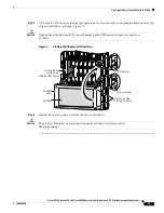
Upper and Lower Blower Module Orientation

Illustrations in this procedure show the removal and replacement of the upper blower module. The 
procedure to replace the lower blower module is the same except for the orientation of the blower 
module
.

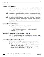
Heads-up orientation—Install the blower module in the upper bay in the “heads-up” orientation with 
the three fan air intake openings face down.

Heads-down orientation—Install the blower module in the lower blower module bay in the 
“heads-down” orientation with the three fan air intake openings face up.

Summary of Contents for 12000/10/16-BLWER=

Page 1: ...6 Cisco 12416 and Cisco 12816 routers Depending on your system these components may not look exactly like those in your chassis but the removal and replacement procedures are essentially the same For clarity most chassis covers are not shown in the illustrations Blower Module Compatibility There are currently two types of blower modules in use for the Cisco 12016 Cisco 12416 and Cisco 12816 router...

Page 2: ...n for the Cisco 12016 Cisco 12416 and Cisco 12816 Series Router publication that shipped with the router PN 78 4347 xx Cisco 12016 Cisco 12416 and Cisco 12816 Router Installation and Configuration Guide For additional information about obtaining documentation see the Obtaining Documentation section on page 14 Safety Guidelines Before you perform any procedure in this publication review the safety ...

Page 3: ...PK T Q OC 3 STM POS 6DS3 SMB P H F DOWN LOOP RA LA CDHNT CD TX 0 RX TX 1 RX TX 2 RX TX 3 RX TX 4 RX TX 5 RX 12DS3 SMB P H F DOWN LOOP RA LA CDHNT CD TX 0 RX TX 1 RX TX 2 RX TX 3 RX TX 4 RX TX 5 RX TX 6 RX TX 7 RX TX 8 RX TX 9 RX TX 10 RX TX 11 RX AC TIV E CA RR IE R RX PK T OC 48 STM 16 SCPOS AC TI VE 0 CA RR IE R RX CE LL OC 12 STM 4 ATM FAST ETERNET SL OT 0 ROUTE PROCESSOR SL OT 1 CO LL LIN K TX...

Page 4: ... to system operation the system should not operate with mixed blower modules in the router for more than 5 minutes Required Tools and Equipment You need the following tools and equipment to install the blower module Number 2 Phillips screwdriver 3 16 inch flat blade screwdriver An electrostatic discharge ESD preventive wrist or ankle strap with connection cord Vacuum cleaner to clean the air filte...

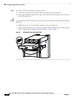
Page 5: ...e chassis Figure 2 a Loosen the captive screw on each side of the blower module b Pull out the blower module halfway from the module bay c Slide out the blower module completely from the module bay while supporting it with your other hand Warning The blower module weighs approximately 20 pounds 9 kg Use two hands when handling the blower module Figure 2 Removing the Upper Blower Module PWR OK FAUL...

Page 6: ...t mates with the backplane connector at the back of the module bay Caution To prevent damage to the connectors do not use excessive force when inserting the blower module into the chassis c Tighten the captive screws on the blower module to secure it to the chassis The green OK status indicator on the front of the blower module should light If the OK indicator does not light see the Troubleshootin...

Page 7: ...fter several attempts to reseat the blower module replace it with a spare If the spare blower module also fails power off the router and contact a Cisco service representative for assistance FAIL red This indicator remains off during normal operation If this indicator is on the system has detected a fan failure or other fault in the blower module If this indicator remains on and the blower module ...

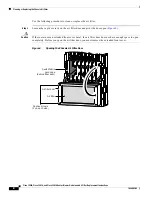
Page 8: ...aution If the router uses an extended front cover bezel the air filter door does not have enough space to open completely Before you open the air filter door you must remove the extended front cover Figure 4 Opening the Chassis Air Filter Door ALARM CS C 0 FA IL 1 0 1 2 EN AB LE D SF C Q OC 3 STM POS 6DS3 SMB P H F 12DS3 SMB P H F RX TX 11 RX OC 48 STM 16 SCPOS OC 12 STM 4 ATM FAST ETERNET ROUTE P...

Page 9: ...ually check the condition of the air filter to determine whether to clean or install a new replacement Dirty You can vacuum or replace the filter Caution Do not vacuum the air filter while it is installed in the chassis You must remove the air filter completely before you clean it to prevent contaminants from being drawn into the bays or cage Worn or torn If the filter appears worn or torn dispose...

Page 10: ... on the back of the air filter to face toward the switch fabric and alarm card cage Slide the new or cleaned air filter into the air filter door Figure 6 Figure 6 Installing the Chassis Air Filter ALARM CS C 0 FA IL 1 0 1 2 EN AB LE D SF C Q OC 3 STM POS 6DS3 SMB P H F 12DS3 SMB P H F RX TX 11 RX OC 48 STM 16 SCPOS OC 12 STM 4 ATM FAST ETERNET ROUTE PROCESSOR 27966 Air filter Air filter door ...

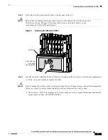
Page 11: ... damaging the EMI preventive gasket contacts on the door Figure 7 Closing the Chassis Air Filter Door Step 6 Tighten the captive screws to secure the door to the chassis Caution The air filter door must be closed and secured at all times to maintain correct EMI performance ALARM CS C 0 FA IL 1 0 1 2 EN AB LE D SF C Q OC 3 STM POS 6DS3 SMB P H F 12DS3 SMB P H F RX TX 11 RX OC 48 STM 16 SCPOS OC 12 ...

Page 12: ...l area is likely to cause harmful interference in which case users will be required to correct the interference at their own expense Modifying the equipment without Cisco authorization may result in the equipment no longer complying with FCC requirements for Class A digital devices In that event your right to use the equipment may be limited by FCC regulation and you may be required to correct any...

Page 13: ...lation environments telecommunication centers and other indoor locations VCCI Class A Notice for Japan Class A Notice for Hungary Warning This is a Class A product based on the standard of the Voluntary Control Council for Interference by Information Technology Equipment VCCI If this equipment is used in a domestic environment radio disturbance may arise When such trouble occurs the user may be re...

Page 14: ... Wide Web at this URL http www cisco com univercd home home htm You can access the Cisco website at this URL http www cisco com International Cisco websites can be accessed from this URL http www cisco com public countries_languages shtml Warning This is a Class A Information Product when used in residential environment it may cause radio frequency interference under such circumstances the user ma...

Page 15: ...ents in e mail to bug doc cisco com You can submit comments by using the response card if present behind the front cover of your document or by writing to the following address Cisco Systems Attn Customer Document Ordering 170 West Tasman Drive San Jose CA 95134 9883 We appreciate your comments Obtaining Technical Assistance For all customers partners resellers and distributors who hold valid Cisc...

Page 16: ...ill commit all necessary resources around the clock to resolve the situation Priority 2 P2 Operation of an existing network is severely degraded or significant aspects of your business operation are negatively affected by inadequate performance of Cisco products You and Cisco will commit full time resources during normal business hours to resolve the situation Priority 3 P3 Operational performance...

Page 17: ...access Packet magazine at this URL http www cisco com go packet iQ Magazine is the Cisco bimonthly publication that delivers the latest information about Internet business strategies for executives You can access iQ Magazine at this URL http www cisco com go iqmagazine Internet Protocol Journal is a quarterly journal published by Cisco Systems for engineering professionals involved in designing de...

Page 18: ...twork Expert logo Cisco IOS Cisco Press Cisco Systems Cisco Systems Capital the Cisco Systems logo Cisco Unity Enterprise Solver EtherChannel EtherFast EtherSwitch Fast Step Follow Me Browsing FormShare GigaDrive HomeLink Internet Quotient IOS iPhone IP TV iQ Expertise the iQ logo iQ Net Readiness Scorecard iQuick Study LightStream Linksys MeetingPlace MGX Networking Academy Network Registrar PIX ...

Reviews: