DCC-HD3
Rev. 905-0118-00
©2017 CIS Corporation. All rights reserved.
9
7.3.
<Reference> surface temperature of each device in the CIS chassis (29mm
×
29mm
×
77mm)
Ambient
temperature
25
℃
40
℃
45
℃
Image sensor
58
73
78
FPGA
55.7
70.7
75.7
CPU
51.7
66.7
71.7
SDI IC
55.1
70.1
75.1
8.
GenLock
Input analog external sync signals (black burst or 3-value SYNC) to the EXT SYNC IN terminal of 6pins connector to
enable Gen Lock function.
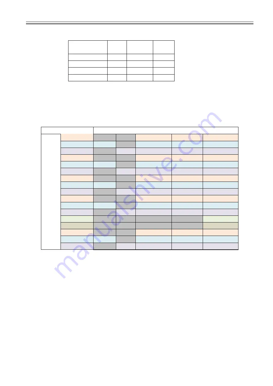
The external sync signals to be supplied shall depend on its video output format, therefore, please refer to the chart
below and input appropriate signals.
EXT SYNC
IN
CA
M
ER
A FO
R
M
AT
1080p60A
1080i60
720p60
1080p30
1080p59.9A
NTSC
1080i59.9
720p59.9
1080p29.9
1080p50A
PAL
1080i50
720p50
1080p25
1080p60B
1080i60
720p60
1080p30
1080p59.9B
NTSC
1080i59.9
720p59.9
1080p29.9
1080p50B
PAL
1080i50
720p50
1080p25
1080i60
1080i60
720p60
1080p30
1080i59.94
NTSC
1080i59.9
720p59.9
1080p29.9
1080i50
PAL
1080i50
720p50
1080p25
1080p30
1080i60
720p60
1080p30
1080p29.9
NTSC
1080i59.9
720p59.9
1080p29.9
1080p25
PAL
1080i50
720p50
1080p25
1080p24
1080p24
1080p23
1080p23.9
720p60
1080i60
720p60
1080p30
720p59.9
NTSC
1080i59.9
720p59.9
1080p29.9
720p50
PAL
1080i50
720p50
1080p25
・
Input Black Burst signals for NTSC/PAL signal.
・
Input 3-value SYNC signals for other than NTSC/PAL signal.
・
EXT SYNC IN is terminated with 75Ω. (It becomes high impedance when camera power is OFF).
・
When the external signals specified above are input, the camera becomes external sync mode automatically.
・
When no external signal is input, the camera operates in internal sync mode.
・
The image may be disturbed right after the external signal is input, but this is not malfunction.
・
When a signal other than specified above combination is input to the EXT SYNC IN terminal, the image might be
disturbed or no image might be output.
9.
LTC (Longitudinal Time code)
Time code can be inserted into 3G/HD SDI signals.
Input LTC signals (time code) to the LTC IN terminal of the 6pins connector to insert external time code.
And, when no signal is input into the LTC IN terminal, internal time code can be inserted.
Internal time code starts with 00:00:00. 00 when power is ON, and when any signals are input into the LTC IN terminal,
it will be switched to the external time code.
With this situation, if no signal is input into the LTC IN terminal, it starts self-running from the set time code.
Signal Format: SMPTE Time code Signal Level: 0.5 ~ 2[Vp-p]


