


CIS
-
CRS112
-
8P MANAGED L2
-
L3 NETWORK SWITCH
PRODUCT MANUAL
1. Welcome to Custom Integration Solutions
™
Thank you for purchasing CIS devices. Our solutions make it easy for integrators to deploy networks in home and business
settings with minimal configuration. Our support team can provide assistance in setting up the equipment and answering your
questions.
3. Overview
The CIS
-
CRS112
-
8P switch is equipped with eight Gigabit Ethernet ports and four SFP+ ports.
The switch is pre
-
configured, with all ports switched together. We recommend you to set up a password to secure your device.
This unit is compatible with 1.25G SFP and 10G SFP+ modules. The device is capable of powering other devices through PoE.
Power
The CIS
-
CRS112
-
8P is powered by the included power supply.
PoE output
This device can supply PoE power to external devices from its ethernet ports. The output voltage will be selected automatical-
ly, depending on what kind of voltage the connected device requires. The device can power both 802.3af/at devices and devic-
es that accept passive PoE power. If necessary, the output voltage can be switched manually.
By default the PoE mode is set to auto. It will not damage non
-
PoE devices and will auto
-
detect devices with PoE support and
their required voltage. Once a PoE device is detected, it will be powered and the PoE LEDs will turn on.
The CIS
-
CRS112
-
8P can power 802.3af/at devices if 48
-
57V DC input is used (unit will automatically detect and provide correct
power to devices). Max Current is 1 A per port if input the voltage is 18
-
28 V, and 450 mA if the input voltage is 48
-
57 V. Total
limit is 2.8A@24V and 1.4A@48
-
57V.
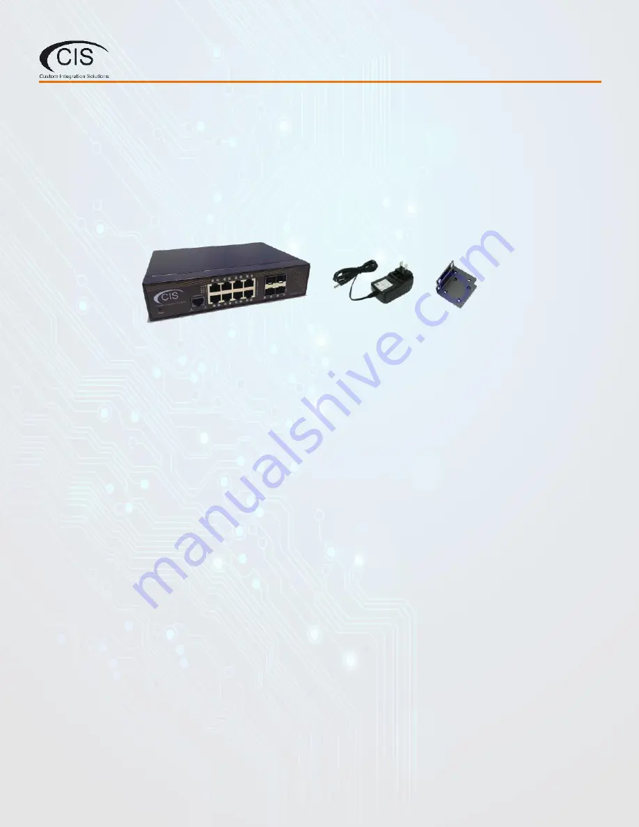
2. Package Contents
Switch (1)
Rack Ears (2)
DC Adapter (1)


