18
RECmax Lpd
Instruction Manual
with the microprocessor the relay will not close.
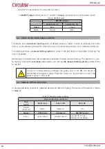
ON/OFF output
(terminals 16, 17 and 18 in
) indicates status of the main switch.
Table 12: ON/OFF output�
Main switch
ON/OFF output
Contact 16 - 17
Contact 16 - 18
Closed
Open
Closed
Open
Closed
Open
4�8�- RESET LEVER AND MANUAL LOCKING
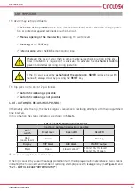
The device has a
), its default position is down. In case of reclosing, the motor
lever is raised actuating the switch. After the reset, the motor lever returns to its downward position.
The device also has a
manual locking system
to prevent the possibility of automatic reclosing. The
lever is sealable.
Reclosing of the device can be completely prevented through manual locking. The operation is per-
formed by moving the
reset lever
downwards and moving
the manual locking system
(yellow catch)
to the left.
In case of manual locking, although the green LED is not ON, the device is
connected to the power supply. Therefore, there is a risk of electric shock if the
power supply is not cut off.
4�9�- NORMAL OPERATING STATUS
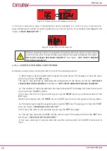
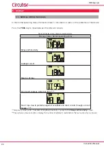
In normal operating conditions, powered device and without tripping, the status of the device is shown
in
Table 13: Normal operating conditions�
Normal operating conditions
Main
switch
Reset lever
Green LED
Red LED
Closed
(Lever up)
Down
Power on
Off
Display
TRIP Alarm
AUX Alarm
ON/OFF output
Green
open contact
closed contact
contact 16-17: open
contact 16-18: closed


