56
RECmax-CVM
Instruction Manual
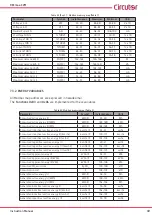
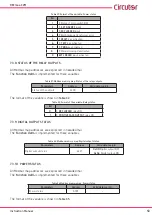
Table 42:Modbus memory map: Programming the Digital Output�
Programming the digital output
Configuration variable
Address
Valid data margin
Default
value
Maximum value or energy pulse
2B0C-2B0D
according to variable
0
Minimum value
2B0E-2B0F
according to variable
0
Variable code
2B10
0
Connection delay
(8)
2B11
0 - 9999
seconds
0
Pulse width
(8)
2B11
0 - 9999
ms
0
Hysteresis
2B12
0 - 99
%
0
Interlocking (latch)
2B13
0 :
No
1:
Yes
0
Disconnection delay
2B14
0 - 9999
seconds
0
Status of the contacts
2B15
0 :
Normally open
1:
Normally closed
0
(8)
The
Connection delay
or
Pulse width
variables are in the same direction and depend on whether an alarm or energy
pulse has been configured or not�
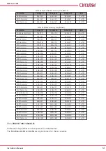
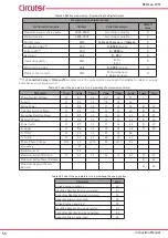
Table 43: Code of the parameters for programming the measurement alarm�
Parameter
Phase
Code
Phase
Code
Phase
Code
Phase
Code
Phase-Neutral Voltage
L1
01
L2
09
L3
17
-
-
Current
L1
02
L2
10
L3
18
-
-
Active Power
L1
03
L2
11
L3
19
III
25
Inductive Reactive Power
L1
04
L2
12
L3
20
III
26
Capacitive Reactive Power
L1
05
L2
13
L3
21
III
27
Apparent Power
L1
06
L2
14
L3
22
III
28
Power factor
L1
07
L2
15
L3
23
III
29
Cosine
φ
L1
08
L2
16
L3
24
III
30
% THD V
L1
36
L2
37
L3
38
-
-
% THD A
L1
39
L2
40
L3
41
-
-
Phase-Phase Voltage
L1/2
32
L2/3
33
L3/1
34
-
-
Frequency
-
31
-
-
-
-
-
-
Neutral current
-
35
-
-
-
-
-
-
Maximum Current Demand
L1
45
L2
46
L3
47
III
44
Maximum Active Power Demand
-
-
-
-
-
-
III
42
Maximum Apparent Power
Demand
-
-
-
-
-
-
III
43
Table 44: Code of the parameters for programming the energy pulses�
Parameter
Code
Active Energy consumed
49
Inductive Reactive Energy consumed
51
Capacitive Reactive Energy consumed
53
Apparent energy consumed
55
Active Energy generated
59
Inductive Reactive Energy generated
61
Capacitive Reactive Energy generated
63
Apparent Energy generated
65

