6
VALVE SETTING
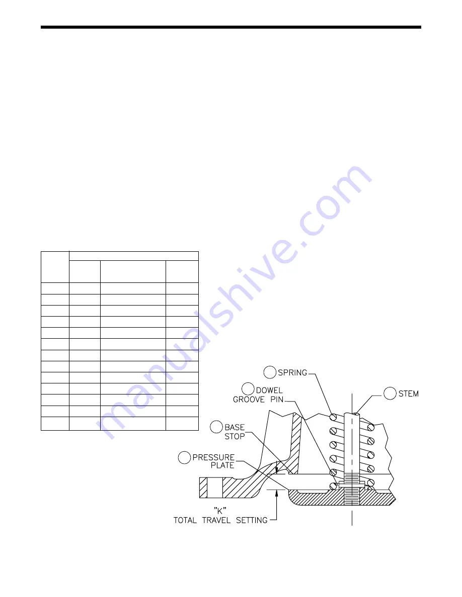
Valve setting is gaged at K to establish correct stem
length and diaphragm position. Dimension “K” is sup-
plied with each replacement stem. For metal dia-
phragm valves, “K” is cast on the upper face of pres-
sure plate (15) (Fig. 6).
To install new stem (12), fasten disc (7) (see Fig. 7)
firmly on stem with stem nut. Insert stem and disc
assembly in valve and screw on pressure plate (15).
Omit spring (13) for this operation. Hold disc on seat
and adjust position of pressure plate until valve setting
“K” is reached. Push pressure plate against stops in
base (11). Remove disc, drop out pressure plate and
stem, drill and insert dowel pin (14) to lock the joint.
Grind off stem projection flush with face of pressure
plate.
VALVE
TRAVEL SETTING
SIZE
TOTAL
GROOVE
DRILL
TRAVEL
PIN
SIZE
3/4
1/4
1/8 X 11/16
1/8
1
5/16
1/8 X 11/16
1/8
1
1
⁄
4
3/8
5/32 X 13/16
5/32
1
1
⁄
2
7/16
5/32 X 13/16
5/32
2
9/16
5/32 X 15/16
5/32
2
1
⁄
2
1
1
⁄
16
3/16 X 15/16
3/16
3
1
3
⁄
16
3/16 X 1
3
⁄
8
3/16
4
1
1
⁄
16
1/4 X 1
3
⁄
4
1/4
5
1
5
⁄
16
5/16 X 1
3
⁄
4
5/16
6
1
9
⁄
16
5/16 X 2
5/16
8
2
1
⁄
16
3/8 X 2
3/8
10
2
9
⁄
16
3/8 X 2
1
⁄
2
3/8
12
3
1
⁄
16
1/2 X 2
3
⁄
4
1/2
FIGURE 6
REPLACING SEAT RINGS
These joints should be made up with Copaltite,
Permatex or equal high temperature gasket com-
pound. Remove old compound from body and seat
ring with a wire brush. Apply new compound sparing-
ly to both parts, threads and shoulders. Let stand until
tacky before assembling.
GRINDING IN (Lapping)
Seats and discs should never require more than the
lightest touch up with very fine (400 grit) grinding com-
pound. Heavy grinding will produce galling, wider
seating surface and a groove in the disc, all of which
tend to cause leakage. Reface a damaged surface
before attempting to grind it in. Grind sparingly.
Main stem (12) shown on Figure 6 is slotted for rotation
with a screwdriver, Valve spring (13) is omitted from
the assembly during grinding. Slip the stem into its
normal position. apply compound to the disc, place it
on the stem and tighten with one stem nut.
After grinding, disassemble and clean all parts.
MAINTENANCE
15
11
12
13
14


