Circor IMO GA Series Installation And Service Instruction Download Page 4

4

www.imo.se

GA

 0601.03 en-GB, ID-No.: 901930331, 161-490/A

Start-up

Before starting

Check that all valves necessary for the operation 

are fully open and set the pressure to minimum by 

turning the set screw CCW.

Starting

Start the pump (or system).

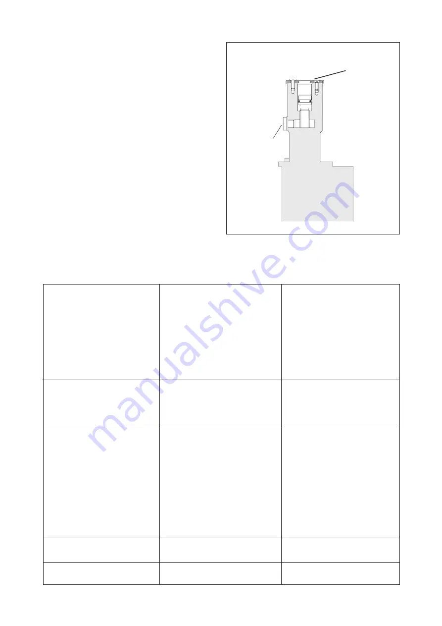
Deaerate the valve and slowly increase the pressure 

to the desired value by using the set screw.

In horizontal installations with the outlet downwards 

and in vertical installations this is done by opening 

the deaeration plug on the spring housing a few 

turns and when liquid is coming out, closing the plug. 

In horizontal installations with the outlet upwards the 

deaeration will be done automatically.

If the valve does not work properly see ”Trouble 

shooting”.

- The pressure relief valve is set 

too low. 

- Counter pressure in the pump 

discharge line is too low due to a 

major leakage.

- The valve piston of the pres-

sure relief valve is stuck in open 

position.

- The valve is too small.

- Improper valve spring.

Pressure too low

What to do

Problem

Cause

Pressure too high

Pressure is fluctuating

”Hunting”

Pressure accumulation too big

Pressure drops below set value 

when overflow increases

- The pressure relief valve is set 

too high.

- The valve is too big.

- Trapped air in the valve

- Too high viscosity.

- Liquid too cold.

- Valve internals damaged due to 

wear or corrosion.

- The throttle screw is not tuned to 

the system.

- The throttle screw is not tuned to 

the system.

Re-adjust the pressure relief 

valve.
Check the components in the 

discharge line inclusive the 

recipients.
Check the valve. See under 

”dismantling”.

Contact your IMO AB representative.

Contact your IMO AB representative.

Re-adjust the pressure relief 

valve.
Contact your IMO AB representa

-

tive.

See ”Starting”

The compensation in the valve is 

too high for the conditions. The 

Compensator piston must be 

adjusted. Contact your IMO AB 

representative.
Run the system till operating tem

-

perature is reached. If problem 

still remains, see above.
Open the valve. See under ”Dis

-

mantling”.

Adjust the throttle screw 647 CW. 

Adjust the throttle screw 647 

CCW. 

Fig. 3 

Trouble shooting

Deaeration

plug

537

Set

screw

608

Summary of Contents for IMO GA Series

Page 1: ...up Trouble shooting 4 Sectional view 5 List of components Ordering code 6 Useful tools GAD springs 7 GAR GAS dismantling reassembly 8 GAD dismantling reassembly 10 Before commencing any work read thi...

Page 2: ...s GAD 065 DIN flanged pipe connections Identification of safety instructions Non compliance of safety instructions identified by the following symbol could affect safety for persons Safety instruction...

Page 3: ...tions to avoid danger are to be taken Pressure testing and flushing The system must be flushed and pressure tested before connecting the valve If corrosive liquid such as water is used for the test th...

Page 4: ...ring Pressure too low What to do Problem Cause Pressure too high Pressure is fluctuating Hunting Pressure accumulation too big Pressure drops below set value when overflow increases The pressure relie...

Page 5: ...GAS Fig 4 Fig 5 646 648 647 608 609 605 626 658 601 497A 497B 4800 614 618 625 617 451 615 612B 602 612A 212 497 497C 537 537A 612C 213 623 626A 626 609 6010 611 615 451 602 612 617 618 625 614 480 64...

Page 6: ...GAS T075 136069 136093 136127 136150 GAS T100 189495 145409 143867 144394 GAD T008 132928 GAD T040 132902 GAD T075 132894 GAD T100 132910 423 O ring 152447 016717 016733 016782 602 O ring 016741 01676...

Page 7: ...213 612C 623 615 213 612C 615 213 612C 615 213 612C 615 T008 T040 T075 T100 1 Valve spring 26 Washers 25 Washers 32 Washers GAD spring 615 Assembly drawings Fig 7 O rings Range 2 8 bar Range 6 40 bar...

Page 8: ...oving and opening the valve C Fig 10 Loosen screws 451 Remove valve cover 601 and collect the washers 611 and 612 and the valve spring 615 611 615 612 601 451 Fig 9 617 618 625 614 Carefully pull out...

Page 9: ...609 Unscrew the set screw 608 and replace the O ring 605 Fit the set screw 608 back into place again Grease the new O ring before mounting it I Reassemble in reversed order Put the valve back into the...

Page 10: ...the O ring 605 Replace the O ring if necessary Loosen and remove the screws 451 Re move the valve cover 601 and collect the valve assembly A B C D 213 623 for T008 615 for T008 612C 213 612C 615 T040...

Page 11: ...ts Check the poppet 614 especially the groove for the retaining ring 212 Replace it if damaged Fig 24 Fig 25 Fig 26 Replace the O ring 602 if necessary Lubri cate the new O ring before mounting it 646...

Page 12: ...12 www imo se GA 0601 03 en GB ID No 901930331 161 490 A Adress IMO AB PO Box 42090 126 14 Stockholm Sweden...

Reviews: