background image

1. 

Remove bolts (6) from inboard cover (4) and then remove inboard cover (4) from pump housing (1). 

2.  For lip seal installed pumps, remove lip seal (16) and O-ring (31) from inboard cover (4).  For 

mechanical seal installed pumps, remove stationary seat of seal (16) and O-ring (31) from inboard 
cover (4). 


CAUTION

ATTENTION


In next step, the rotors will be removed from the pump. They will come out as a unit.  
Use care to support the rotors set as it is withdrawn from housing so idlers will not be 
dropped on floor.  


3. 

Remove power rotor (7) and idlers (8) by grasping shaft of power rotor and easing it out of housing 
(1). Set idlers (8) aside. 


4. 

For mechanical seal pumps, perform the following: 

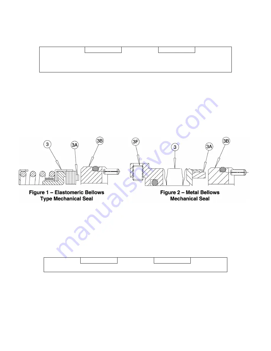
a)  For Elastomeric Bellows Type Seals (see Figure 2 below) – Slide rotating assembly (3) of 

mechanical seal (16) off power rotor (7). 

b)  For Metal Bellows Type Seals (see Fig 3 below) – Loosen set screw (3F) and slide rotating 

assembly (3) from power rotor (7). 


NOTE:


IF ONLY REPLACING SEALS

, pump disassembly is complete. For seal installation, proceed 

to section H5 and complete steps 3 and 7 through 10 and 12 through 16.  For mechanical 
seal installation, complete steps 4 through 9 and 11 through 16. If the remainder of pump 
needs to be disassembled, proceed below. 


5. 

Remove ball bearing (11) from power rotor (7) by first removing retaining ring (15) from groove in 
power rotor (7) shaft.  Ball bearing (11) can then be removed with a gear puller or arbor press. 


CAUTION

ATTENTION


Removal of bearing by force applied to its outer ring could damage bearing.  

 
NOTE: 

Imo Pump strongly recommends replacement of the ball bearing every time the bearing is 
pressed off the power rotor. 


6. 

Remove inlet head (2) by removing four bolts (3 or 6). 

 
7. 

Remove O-ring (31 or 26 depending on pump size) from inlet head (2). 


Summary of Contents for IMO AA3G Series

Page 1: ...stallation Operation Maintenance and Troubleshooting Manual No SRM00046 this manual and associated component manuals supplied with the unit should be read thoroughly prior to pump installation start u...

Page 2: ...s Safety instructions where electrical safety is involved are identified by Safety instructions which shall be considered for reasons of safe operation of the pump and or protection of the pump itself...

Page 3: ...wording Imo Pump must assume the personnel assigned to operate and maintain supplied equipment and apply this instruction manual have sufficient technical knowledge and are experienced to apply sound...

Page 4: ...NS Never operate with water The pump is designed for liquids having the general characteristics of oil E 2 OPERATING LIMITS CAUTION ATTENTION Operating conditions such as speed fluid viscosity tempera...

Page 5: ...r 4 Bolt See Note 15 1 Retaining Ring 4 1 Inboard Cover 16X 1 Seal 5 4 Bolt Ext RV 19 1 Breakdown Bushing Steel Pumps Only 6 4 6 or 8 Bolt See Note 26X 1 O Ring 118 to 162 7 1 Power Rotor 31X 1 O Ring...

Page 6: ...isassembly of pump may make floor slippery and cause personal injury The following steps are required before starting any maintenance action a De energize and lock out power to driver and tag power co...

Page 7: ...16 off power rotor 7 b For Metal Bellows Type Seals see Fig 3 below Loosen set screw 3F and slide rotating assembly 3 from power rotor 7 NOTE IF ONLY REPLACING SEALS pump disassembly is complete For...

Page 8: ...rotating assembly 3 on power rotor shaft 7 For 95 sizes only be sure slots in rotating assembly 3 line up with seal return hole in power rotor shaft Tighten setscrew 3F Do not touch carbon seal face...

Page 9: ...instructions regarding installation alignment operation and trouble shooting see General Installation Operation Maintenance Troubleshooting Manual CA 1 J FIELD AND FACTORY SERVICE AND PARTS Imo Pump...

Page 10: ...Figure 3 AA3G 95 Iron Pump Assembly 8...

Page 11: ...Figure 4 AA3G 95 Steel Pump Assembly 9...

Page 12: ...Figure 5 AA3G 118 to 162 Iron ump Assembly 10...

Page 13: ...Figure 6 AA3G 118 to 162 Steel Pump Assembly 11...

Page 14: ...ivery of installation tool Material Steel Gray Iron Nylon VC or any hard material that will give a smooth finish A B C D E Overall Length OD ID Installation Angle Taper in in in Deg Deg 3G 95 1 1 8 62...

Page 15: ...IRCOR 1710 Airport Road 28110 PO Box 5020 Monroe NC USA 28111 5020 Tel 1 877 853 7867 Fax 1 704 289 9273 Email cc circor com Web www circorpt com 2020 CIRCOR Pumps North America LLC All rights reserve...

Reviews: