M6 SERIES IOM
6th EDITION
ISSUED 12/2014
28
D. Changing Fail Configurations
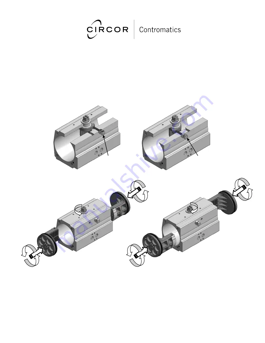
Follow these steps to change the fail configuration of the actuator:
1. Disassemble the actuator as described on pg.21 steps 1-7.
2. Using the proper size crescent wrench, rotate the pinion to its new orientation when in the “fail” position
(actuator closed), and set the new closed stop.
3. Check the cam to make sure the flat side of the cam is making contact with the stop.
4. Rotate the pinion to the new open position.
5. Rotate the pistons 180 degrees from their original orientation and insert them into the actuator.
6. Finish assembling the actuator as described on pg. 29 starting at step 10.
FCW Closed
Limit Stop
FCCW Closed
Limit Stop
The illustrations above show the “fail” orientation of the pinion for the FCW configuration (Fig. 9.18) and the
FCCW configuration (Fig. 9.19) as described in step 2 above. Also shown above is the correct location for the
closed limit stops for each configuration. Figs. 9.20-9.21 illustrate adjustments that must be made when going from
FCCW to FCW (Fig. 9.20) or when going from FCW to FCCW (Fig. 9.21). Note pinion has been rotated to its new
opening position and the pistons have been rotated 180° from their original position before being inserted into the
body.
Fig. 9.18
Fig. 9.19
Fig. 9.20
Fig. 9.21


