Setup and connection
5.2.3
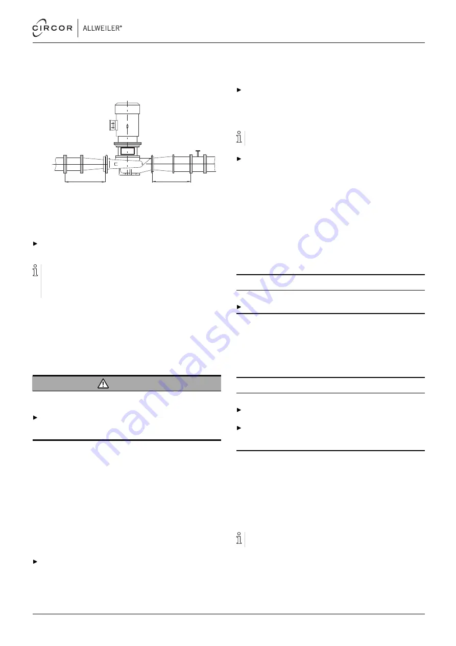
Specifying pipe lengths
A
B
Fig. 8
Straight pipe lengths upstream and downstream
of the pump (recommended)
A > 5 x nominal suction pipe diameter
B > 5 x nominal pressure pipe diameter
Maintain the recommended minimum values when
installing the pump.
Suction side: shorter pipes are possible but may restrict
the hydraulic performance.
Pressure side: shorter pipes are possible but can result in
increased operating noise.
5.2.4
Optimizing cross-section and direction
changes
1. Avoid radii of curvature of less than 1.5 times the nominal
pipe diameter.
2. Avoid abrupt changes of cross-section along the piping.
5.2.5
Discharging leaks
WARNING
Risk of injury and poisoning due to hazardous pumped
liquids!
Safely collect any leaking pumped liquid, then discharge
and dispose of it in accordance with environmental regula-
tions.
1. Provide equipment for collecting and discharging leaking
liquids.
2. Ensure the free discharge of leaking liquids.
5.2.6
Providing safety and control devices
(recommended)
Avoid impurities
1. Integrate a filter in the suction pipe.
2. To monitor impurities, install a differential pressure gauge
with a contact manometer.
Avoid reverse running
Install a non-return valve between the pressure flange and
the gate valve to ensure the medium does not flow back
when the pump is switched off.
Avoid running empty
For suction operation: install a foot valve in the suction pipe
to prevent the pump and suction pipe from running empty
during downtimes.
Make provisions for isolating and shutting off the pipes
For maintenance and repair work.
Provide shut-off devices in the suction and pressure pipes.
Allow measurements of the operating conditions
1. Provide manometers for pressure measurements in the
suction and pressure pipes.
2. Provide load monitors (overload and underload) on the
motor side.
3. Provide for pump-side temperature measurements.
5.3
Installing in the pipe
5.3.1
Keeping the piping clean
NOTE
Material damage due to impurities in the pump!
Make sure no impurities can enter the pump.
1. Clean all piping parts and armatures prior to assembly.
2. Ensure no flange seals protrude inwards.
3. Remove any blind flanges, plugs, protective foils and/or
protective paint from flanges.
5.3.2
Installing the pump unit without feet/base
NOTE
Material damage due to excessive forces!
Make sure the pipe is able to bear the weight of the pump
aggregate and all operating forces which occur.
Make sure that the distance and alignment of the pipe
flanges comply with the pump dimensions (→ setup draw-
ing).
1. Remove the transport and sealing covers from the pump.
2. Lifting the pump unit (→ 4.1 Transport, Page 14).
3. Raise the pump aggregate between the pipe ends.
Observe the pumping direction in the process.
4. Screw the suction flange and pressure flange to the pipe,
complying with the prescribed tightening torques.
5.3.3
Setting up pump unit with feet/base
Pump units with a base are installed vertically (motor at the
top).
1. Lift the pump unit and set it down at the installation location
2. Install the pump unit (→ setup drawing).
550 113 – 146-900/E
BA-2021.06 en-US
NI series
17


