CIGWELD 300Pi Operating Manual Download Page 28

TRANSTIG 300Pi

INSTALLATION, OPERATION AND SETUP 

3-10 

Manual 0-5309

3.07  Setup for TIG (GTAW) Welding

A.  Select HF TIG or Lift TIG mode with the process selection control (refer to Section 3.06.11 for further 

information).

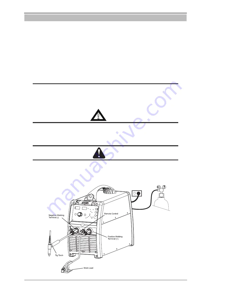
B.  Connect the TIG Torch to the negative welding terminal (-). Welding current flows from the power source 

via heavy duty bayonet type terminals. It is essential, however, that the male plug is inserted and turned 

securely to achieve a sound electrical connection.

C.  Connect the work lead to the positive welding terminal (+). Welding current flows from the Power Source 

via heavy duty bayonet type terminals. It is essential, however, that the male plug is inserted and turned 

securely to achieve a sound electrical connection. 

D.  Connect the TIG torch trigger switch via the 8 pin socket located on the front of the power source as shown 

below. The TIG torch will require a trigger switch to operate in HF TIG and Lift TIG Mode.

NOTE

If the TIG torch has a remote TIG torch current control fitted then it will require to be connected to 

the 8 pin socket. (Refer to section 3.06.08 Remote Control Socket for further information).

E.  Fit the welding grade shielding gas regulator/flowmeter to the shielding gas cylinder (refer to Section 3.10) 

then connect the shielding gas hose from the Power Source to the regulator/flowmeter outlet.

!

WARNING

Before connecting the work clamp to the work and inserting the tungsten electrode in the TIG Torch 

make sure the mains power supply is switched off.
Secure the welding grade shielding gas cylinder in an upright position by chaining it to a stationary 

support to prevent falling or tipping.

CAUTION

Remove any packaging material prior to use. Do not block the air vents at the front or rear of the 

Welding Power Source.
Loose welding terminal connections can cause overheating and result in the male plug being fused 

in the terminal.

A-12102

Figure 3-6: Setup for TIG Welding

Summary of Contents for 300Pi

Page 1: ...A 12096 A 12096 300Pi Operating Manual Revision AD Issue Date December 10 2013 Manual No 0 5309 Operating Features TRANSTIG welding Inverter...

Page 2: ...p you to avoid potential hazards that may exist when working with this product YOU ARE IN GOOD COMPANY The Brand of Choice for Contractors and Fabricators Worldwide CIGWELD is the Market Leading Brand...

Page 3: ...4 7391 www cigweld com au Copyright 2013 by CIGWELD Pty Ltd All rights reserved Reproduction of this work in whole or in part without written permission of the publisher is prohibited The publisher do...

Page 4: ...03 Ventilation 3 1 3 04 Mains Supply Voltage Requirements 3 1 3 05 Electromagnetic Compatibility 3 1 3 06 Transtig 300Pi Power Source Controls Indicators and Features 3 3 3 07 Setup for TIG GTAW Weldi...

Page 5: ...PARTS 6 1 6 01 Power Source 6 1 6 02 TIG Torch W4014604 6 3 APPENDIX TRANSTIG 300Pi CIRCUIT DIAGRAM CIGWELD LIMITED WARRANTY TERMS TERMS OF WARRANTY January 2013 WARRANTY SCHEDULE January 2013 GLOBAL...

Page 6: ......

Page 7: ...ood electrical earth ground 11 Do not touch electrode while in contact with the work ground circuit 12 Use only well maintained equipment Repair or replace damaged parts at once 13 In confined spaces...

Page 8: ...imate Range of Welding Current in Amps Minimum Shade Number of Filter s Manual Metal Arc Welding covered electrodes MMAW Less than or equal to 100 8 100 to 200 10 200 to 300 11 300 to 400 12 Greater t...

Page 9: ...yourself and others from flying sparks and hot metal 2 Do not weld where flying sparks can strike flam mable material 3 Remove all flammables within 35 ft 10 7 m of the welding arc If this is not poss...

Page 10: ...California Health Safety code Sec 25249 5 et seq NOTE Considerations About Welding And The Effects of Low Frequency Electric and Magnetic Fields The following is a quotation from the General Con clus...

Page 11: ...Compressed Gas Association 1235 Jefferson Davis Highway Suite 501 Arlington VA 22202 Code for Safety in Welding and Cutting CSA Standard W117 2 from Canadian Standards Association Stan dards Sales 178...

Page 12: ...ons The product is designed and manufactured to a number of standards and technical requirements among them are IEC 60974 10 applicable to Industrial Equipment generic emissions and regulations AS 167...

Page 13: ...n the inside back cover of this manual Include all equipment identification numbers as described above along with a full description of the parts in error Move the equipment to the installation site b...

Page 14: ...ase Circuit Breaker AC Auxiliary Power Remote Duty Cycle Percentage Amperage Voltage Hertz cycles sec Frequency Negative Positive Direct Current DC Protective Earth Ground Line Line Connection Auxilia...

Page 15: ...be used Parts that are broken missing plainly worn distorted or contaminated should be replaced immediately Should such repairs or replacements become necessary it is recommended that such re pairs be...

Page 16: ...minute duty cycle period the following example is used Suppose a Welding Power Source is designed to operate at a 35 duty cycle 300 amperes at 32 volts This means that it has been designed and built...

Page 17: ...e Generator Recommendation refer Note 4 16 1kW 20kVA at 0 8 PF STICK MMAW Welding Output 40 C 10 min 300A 35 32 0V 250A 60 30 0V 200A 100 28 0V TIG GTAW Welding Output 40 C 10 min 315A 40 22 6V 250A 6...

Page 18: ...ers Cigweld recommends that when selecting a generator that the particular power source generator combination be adequately trialled to ensure the combination performs to the users expectations NOTE 5...

Page 19: ...the manufacturer In some cases this remedial 3 01 Environment These units are designed for use in environments with increased hazard of electric shock as outlined in AS 60974 1 and AS 1674 2 A Exampl...

Page 20: ...g area to be considered will depend on the structure of the building and other activities that are taking place The surrounding area may extend beyond the boundaries of the premises C Methods of Reduc...

Page 21: ...ence Screening the entire welding installation may be considered for special applications 3 06 Transtig 300Pi Power Source Controls Indicators and Features Pulse A 12098 Art A 12099_AB Figure 3 1 Fron...

Page 22: ...he value until 1 the Multi Function Control is adjusted in which case the unit will revert to preview mode 2 welding is recommenced in which case actual welding voltage will be displayed or 3 a period...

Page 23: ...e a sound electrical connection CAUTION Loose welding terminal connections can cause overheating and result in the male plug being fused in the bayonet terminal 7 Negative Welding Output Terminal The...

Page 24: ...r 7 Wiper arm connection to 5k ohm remote control Amps GTAW TIG mode potentiometer 8 Not connected Table 3 1 9 Shielding Gas Outlet The Shielding Gas Outlet located on the front panel is a 5 8 18 UNF...

Page 25: ...witch must again be depressed and released thus eliminating the need for the operator to hold the torch trigger Note that when operating in GTAW TIG mode the power source will remain activated until t...

Page 26: ...er is Amps Seconds or Hz The parameter is saved after 20 seconds if there has been no user adjustment 14 Purge Button Press and hold the PURGE button to purge the gas line in LIFT TIG and HF TIG modes...

Page 27: ...oler Remote Control Socket The 4 pin Water Cooler Remote Control Socket is used to connect remote control devices to the welding power source To make connections align keyway insert plug and rotate th...

Page 28: ...torch will require a trigger switch to operate in HF TIG and Lift TIG Mode NOTE If the TIG torch has a remote TIG torch current control fitted then it will require to be connected to the 8 pin socket...

Page 29: ...to 5 0 seconds Factory default is 0 1 second Pulse A 12103 Initial Current This parameter operates in TIG modes only and is used to set the start current for TIG In 4T mode the Initial Current remain...

Page 30: ...ands for Non Pulse mode which is DC operating mode This Shows Panel display for DC Pulse operating mode Note that the display P stands for DC Pulse Mode Pulse Pulse A 12106 Base Current In DC TIG mode...

Page 31: ...09 Pulse Frequency This parameter sets the PULSE FREQUENCY when in DC PULSE operating mode Range is 0 5 to 500Hz Factory default is 100Hz Pulse A 12110 Down Slope This parameter operates in TIG modes...

Page 32: ...ory default is 5 0 seconds Pulse A 12113 3 08 Setup for Manual Arc MMAW Welding A Connect the Electrode Holder lead to the positive welding terminal If in doubt consult the electrode manufacturer Weld...

Page 33: ...Parameter Control Panel Display Hot Start ThisparameteroperatesinSTICKmode to improve the start characteristics for stick electrodes HOT START current is on top of the BASE current e g HOT START curr...

Page 34: ...his feature can be particularly beneficial in providing the operator the ability to compensate for variability in joint fit up in certain situations with particular electrodes In general increasing th...

Page 35: ...dangerously propel a loose part 3 DO NOT remove the regulator from a cylinder without first closing the cylinder valve and releasing gas in the regulator high and low pressure chambers 4 DO NOT use th...

Page 36: ...pen the cylinder valve If opened quickly a sudden pressure surge may damage internal regulator parts 2 With valves on downstream equipment closed adjust regulator to approximate working pressure It is...

Page 37: ...ansporting cylinders that are not secured on a cart designed for such purposes remove regulators 3 11 Foot Control Part No W4015800 Optional Accessory Art A 11338 Figure 3 11 Foot Control Art A 11339...

Page 38: ...displays actual welding current when welding Pressing the pedal to increases the welding current letting up on the pedal decreases the welding current Releasing the pedal completely extinguishes the...

Page 39: ...ed by using the correct electrodes preheating using higher current settings using larger electrodes sizes short runs for larger electrode deposits or tempering in a furnace Hydrogen controlled Electro...

Page 40: ...for welds to be made in positions intermediate between these Some of the common types of welds are shown in Figures 4 1 through 4 8 Art A 07687 Figure 4 1 Flat Position Down Hand Butt Weld Art A 07688...

Page 41: ...al and to produce sound joints In general surfaces being welded should be clean and free of rust scale dirt grease etc Slag should be removed from oxy cut surfaces Typical joint designs are shown in F...

Page 42: ...at first experience difficulty due to the tip of the electrode sticking to the work piece This is caused by making too heavy a contact with the work and failing to withdraw the electrode quickly enou...

Page 43: ...er clean the slag out of the back and deposit a similar weld Art A 07697_AB Tack Weld 20 30 Electrode Tack Weld Figure 4 11 Butt Weld Art A 07698 Figure 4 12 Weld Build up Sequence Heavy plate will re...

Page 44: ...an upright position Use a 3 2mm Ferrocraft 21 electrode and set the current at 100 amps Make yourself comfortable on a seat in front of the job and strike the arc in the corner of the fillet The elect...

Page 45: ...downhand welding Set up a specimen for overhead welding by first tacking a length of angle iron at right angles to another piece of angle iron or a length of waste pipe Then tack this to the work ben...

Page 46: ...ent plate material is heated to a very high temperature and attempts to expand in all directions It is able to do this freely at right angles to the surface of the plate i e through the weld but when...

Page 47: ...etting It is possible in some cases to tell from past experience or to find by trial and error or less frequently to calculate how much distortion will take place in a given welded structure By correc...

Page 48: ...ck Sequence The spaces between the welds are filled in when the welds are cool 2 3 Figure 4 24 Welding Sequence Art A 07711_AB 4 3 2 1 Figure 4 25 Step back Sequence Art A 07712 Figure 4 26 Chain Inte...

Page 49: ...611602 611603 611604 Stainless Steel type for 19Cr 10Ni stainless grades including 201 202 301 302 303 304 304L 305 308 etc Satincrome 309Mo 17 2 5mm 3 2mm 4 0mm 2 5 kg 2 5 kg 2 5 kg 611692 611693 611...

Page 50: ...ery bad chip or grind out irregularities D Lack of penetration with slag trapped beneath weld bead D Use smaller electrode with sufficient current to give adequate penetration Use suitable tools to re...

Page 51: ...ld metal porosity A High levels of sulphur in steel A Use an electrode that is designed for high sul phur steels B Electrodes are damp B Dry electrodes before use C Welding current is too high C Reduc...

Page 52: ...he welding application Welds Made With or Without Addition of Filler Metal Work Piece Can Be Any Commercial Metal Gas Cup Either Ceramic High lmpact or Water Cooled Metal Inert Gas Shields Electrode a...

Page 53: ...um strength steels Pipes tubing roll cages etc CrMo1 CrMo2 RB2 RB3 ER80S B2 ER90S B3 321379 321383 For welding of high strength Cr Mo steels used at elevated tempera tures 308L 309L 316L R308L R309L R...

Page 54: ...small or insufficient penetration or ripples in bead are widely spaced apart Travel speed too fast Reduce travel speed 4 Weld bead too wide or excessive bead build up or excessive penetration in butt...

Page 55: ...t the right size tungsten electrode Refer to Table 4 3 Cigweld Tungsten Electrode Selection Chart B The wrong electrode is being used for the welding job B Select the right size tungsten electrode typ...

Page 56: ...TRANSTIG 300Pi BASIC WELDING GUIDE 4 18 Manual 0 5309...

Page 57: ...mode A Gas hose is damaged A Replace or repair B Gas passage contains impurities B Disconnect gas hose from the rear of power source or wirefeeder and blow out impurities C Gas regulator turned off C...

Page 58: ...ls present inside this Inverter Power Source Do not attempt to open or repair unless you are an accredited CIGWELD Service Provider Discon nect the Welding Power Source from the Mains Supply Voltage b...

Page 59: ...al is required to be earthed and 1 The earth terminal of a fixed power source or 2 The earth terminal of the associated plug of a transportable power source Note that due to the dangers of stray outpu...

Page 60: ...once every 3 months and 2 For fixed equipment at least once every 12 months If equipment is to be used in a hazardous location or environments with a high risk of electrocution as outlined in AS 1674...

Page 61: ...and power levels present inside this product Do not attempt to open or repair unless you are a qualified electrical tradesperson Disconnect the Welding Power Source from the Mains Supply Voltage befor...

Page 62: ...TRANSTIG 300Pi POWER SOURCE PROBLEMS AND ROUTINE SERVICE REQUIREMENTS 5 6 Manual 0 5309...

Page 63: ...TRANSTIG 300Pi Manual 0 5309 6 1 KEY SPARE PARTS SECTION 6 KEY SPARE PARTS 6 01 Power Source Art A 12119_AB Art A 12120_AB...

Page 64: ...6408 Knob Control 10 W7006416 Fan Assembly 11 W7006417 Shielding Gas Inlet Quick Connect 12 W7006409 Mains Supply Switch 3 Pole 13 W7006418 Shielding Gas Outlet 5 8 18 14 W7006419 Dinse Socket 50mm2 1...

Page 65: ...A 11669 Figure 6 2 TIG TORCH SPARE PARTS ITEM PART NO DESCRIPTION 1 W7005900 Trigger assembly for 26F torch 2 W7005901 Handle assembly for 26F torch 3 W7005902 Dinse 50mm for 26F torch 4 W7005903 Flex...

Page 66: ...TRANSTIG 300Pi Manual 0 5309 A 1 APPENDIX APPENDIX TRANSTIG 300Pi CIRCUIT DIAGRAM A 12122_AB...

Page 67: ...R CONSEQUENTIAL DAMAGES SUCH AS BUT NOT LIMITED TO LOST PROFITS AND BUSINESS INTERRUPTION The remedies of the Purchaser set forth herein are exclusive and the liability of CIGWELD with respect to any...

Page 68: ...our Accredited Distributor in writing of its claim within seven 7 days of becoming aware of the basis thereof and at its own expense returning the goods which are the subject of the claim to CIGWELD...

Page 69: ...WARRANTY PERIOD PARTS LABOUR Original main power magnetics 3 Year 2 Year Original main power rectifiers printed circuit boards and power switch semiconductors 2 Year 2 Year All other circuits and com...

Page 70: ...rn of goods to Cigweld or our Nominated Accredited Distributor Accredited Service Provider are the responsibility of the consumer This warranty is given Cigweld Pty Ltd A B N 56007226815 71 Gower Stre...

Page 71: ...1257 224800 PT Victor Technologies Utama Indonesia Jl Angsana II Blok AE No 28 Delta Silicon I Cikarang Sukaresmi Bekasi 17550 Indonesia Tel 62 21 8990 6095 Fax 62 21 8990 6096 1867 http www Victortec...

Page 72: ...Asia Pacific Regional Headquarters 71 Gower Street Preston Victoria Australia 3072 Telephone 61 3 9474 7400 FAX 61 3 9474 7391 Email enquiries cigweld com au www cigweld com au...

Reviews: