CIAS Elettronica S.r.l.
Ed. 1.2
Installation Handbook
Page
64
of
73
ERMO 482X3
PRO
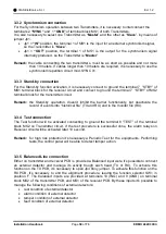
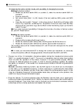
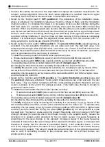
2) Assigning the barrier number locally, with possibility of changing from remote.
Writing
the barrier number:
•
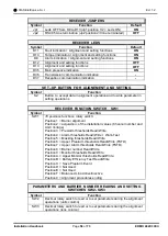
Rotate the decimal switch SW2 on position 0, rotate the decimal switch SW3 on
position 0.
•
Push the button S1.
•
Set a new value (from 1 to 99) means of the two switches SW2 (units) and SW3
(tens),
•
C
lose the micro switch “Tamper”. In this phase leds of Fault (D8) and Tamper (D9)
turn on for 3 seconds, confirming the acquisition of the new value, after that they
will turn off for 3 seconds, to go back at their normal functioning. Open up the micro
switch “Tamper”
NB:
if you wish to prevent possibility of changes from remote of number of barrier number
set, push S1 Reset button.
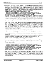
Reading
the barrier number:
•
Rotate the decimal switch SW2 on position 0, rotate the decimal switch SW3 on
position 0.
•
Press and then release the S1reset button,
•
Rotate the decimal switch SW2 (units) until the green led D9 becomes on
•
Rotate the decimal switch SW3 (tens) until the green led D8 becomes on
The reading values will be included between 01 and 99 and will correspond to the actual
barrier number.
NB:
in case you should decide NOT to change the number
just visualized, it’s necessary
to close the radome without changing position of decimal switches SW2 and SW3.
•
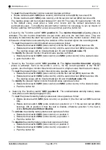
Prepare one of the 16 modulation channels available turning the hexadecimal rotary switch
"SW1" in a position between 0 and F. The use of a modulation channel rather than another
does not alter the operation of the barrier, however, it is good practice prepare different
channels for different barriers of a plant, in order to increase sabotage qualities. By setting
the switch on channel F, if the barrier is in channel alarm condition it would not generate the
alarm event.
Remark
. potentially interfering barriers, due the MW signal of one which can be intercepted
on the other (i.e. for installation reasons), it will be necessary to synchronize the transmitters
by ensuring that one (Master) provide to the other (slave) the synchronization signal. In this
case the modulation frequency of the transmitter slave does not depend on the position of its
switch, but only by the synchronization signal.
•
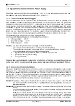
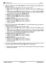
Close the radome. To do this operation place the Radome near the back cover, keeping the
central logo rotated anticlockwise of 20°. Before to close the head ensure that the tilt switch is
vertically positioned. Then fit the front cover to the back cover and rotate it clockwise until the
central logo will be correctly positioned and tighten the screws.


