


(3) Using external snap ring pliers with 90 degree
tips. Insert pliers with tips against bosses and
squeeze forcing bosses out of base.
(4) Pull out the base through mounting ring by
gently rocking pliers. A tool can be made to do the
same. Refer to (Fig. 3).
(5) Disconnect the base wires.
(6) Set base aside and remove base mount ring.
INSTALLATION
(1) Install base mount ring.
(2) Connect the base wires.
(3) Firmly snap base into position inside of instru-
ment panel.
(4) Connect the negative battery cable remote ter-
minal to the remote battery post.
IOD FUSE
DESCRIPTION
All vehicles are equipped with an Ignition-Off
Draw (IOD) fuse that is disconnected within the
Junction Block when the vehicle is shipped from the
factory. Dealer personnel are to reconnect the IOD
fuse in the junction block as part of the preparation
procedures performed just prior to new vehicle deliv-
ery.
The left end of the instrument panel cover has a
snap-fit fuse access panel that can be removed to pro-
vide service access to the fuses in the junction block.
An adhesive-backed fuse layout map is secured to the
instrument panel side of the access panel to ensure
proper fuse identification. The IOD fuse is a 15
ampere mini blade-type fuse, located in fuse cavity #
19.
CIRCUITS INCLUDED WITH IOD FUSE
•
Cluster
•
Body Control Module
•
Diagnostic Connector
•
Map Lamps
•
Glove Box Lamp
•
Courtesy Lamps
•
Compass Mini-Trip Computer
•
Radio
OPERATION
The term ignition-off draw identifies a normal con-
dition where power is being drained from the battery
with the ignition switch in the Off position. The IOD
fuse feeds the memory and sleep mode functions for
some of the electronic modules in the vehicle as well
as various other accessories that require battery cur-
rent when the ignition switch is in the Off position.
The only reason the IOD fuse is disconnected is to
reduce the normal IOD of the vehicle electrical sys-
tem during new vehicle transportation and pre-deliv-
ery storage to reduce battery depletion, while still
allowing vehicle operation so that the vehicle can be
loaded, unloaded and moved as needed by both vehi-
cle transportation company and dealer personnel.
The IOD fuse is disconnected from JB fuse cavity
#19 when the vehicle is shipped from the assembly
plant. Dealer personnel must reconnect the IOD fuse
when the vehicle is being prepared for delivery in
order to restore full electrical system operation. Once
the vehicle is prepared for delivery, the IOD function
of this fuse becomes transparent and the fuse that
has been assigned the IOD designation becomes only
another Fused B(+) circuit fuse.
The IOD fuse can be used by the vehicle owner as
a convenient means of reducing battery depletion
when a vehicle is to be stored for periods not to
exceed about thirty days. However, it must be
remembered that disconnecting the IOD fuse will not
eliminate IOD, but only reduce this normal condition.
If a vehicle will be stored for more than about thirty
days, the battery negative cable should be discon-
nected to eliminate normal IOD; and, the battery
should be tested and recharged at regular intervals
during the vehicle storage period to prevent the bat-
tery from becoming discharged or damaged.
REMOVAL
The Ignition-Off Draw (IOD) fuse is disconnected
from Junction Block fuse cavity # 19 when the vehi-
cle is shipped from the assembly plant. Dealer per-
sonnel must reconnect the IOD fuse when the vehicle
is being prepared for delivery in order to restore full
electrical system operation.
(1) Turn the ignition switch to the Off position.
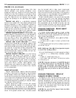
Fig. 3 Tool For Cigar Lighter / Power Outlet
Removal
1 - 2.5MM (3/32 INS.)
2 - WELD
3 - 100MM (4 INS.)
4 - 22.25 TO 22.45MM (7/8 TO 57/64 INS.)
LH
8W-97 POWER DISTRIBUTION
8W - 97 - 3
CIGAR LIGHTER/POWER OUTLET (Continued)
Summary of Contents for 2004 Concorde
Page 2: ......
Page 5: ...Fig 3 FASTENER IDENTIFICATION LH INTRODUCTION 3 FASTENER IDENTIFICATION Continued ...
Page 6: ...Fig 4 FASTENER STRENGTH 4 INTRODUCTION LH FASTENER IDENTIFICATION Continued ...
Page 9: ...Fig 6 METRIC CONVERSION CHART LH INTRODUCTION 7 METRIC SYSTEM Continued ...
Page 14: ......
Page 184: ......
Page 226: ......
Page 246: ......
Page 310: ......
Page 316: ......
Page 330: ......
Page 423: ...Fig 1 SIDE AIRBAG LOCATION TYPICAL LH RESTRAINTS 8O 3 RESTRAINTS Continued ...
Page 448: ......
Page 490: ......
Page 506: ......
Page 510: ......
Page 511: ......
Page 512: ......
Page 513: ......
Page 514: ......
Page 515: ......
Page 516: ......
Page 517: ......
Page 518: ......
Page 519: ......
Page 520: ......
Page 521: ......
Page 522: ......
Page 523: ......
Page 524: ......
Page 525: ......
Page 526: ......
Page 527: ......
Page 528: ......
Page 529: ......
Page 530: ......
Page 531: ......
Page 532: ......
Page 533: ......
Page 534: ......
Page 535: ......
Page 536: ......
Page 537: ......
Page 538: ......
Page 540: ......
Page 541: ......
Page 542: ......
Page 543: ......
Page 544: ......
Page 546: ......
Page 547: ......
Page 548: ......
Page 549: ......
Page 550: ......
Page 551: ......
Page 552: ......
Page 553: ......
Page 554: ......
Page 555: ......
Page 556: ......
Page 557: ......
Page 558: ......
Page 559: ......
Page 560: ......
Page 561: ......
Page 562: ......
Page 563: ......
Page 564: ......
Page 565: ......
Page 566: ......
Page 567: ......
Page 568: ......
Page 569: ......
Page 570: ......
Page 571: ......
Page 572: ......
Page 573: ......
Page 574: ......
Page 575: ......
Page 576: ......
Page 577: ......
Page 578: ......
Page 580: ......
Page 581: ......
Page 582: ......
Page 583: ......
Page 584: ......
Page 585: ......
Page 586: ......
Page 587: ......
Page 588: ......
Page 589: ......
Page 590: ......
Page 591: ......
Page 592: ......
Page 593: ......
Page 594: ......
Page 595: ......
Page 596: ......
Page 597: ......
Page 598: ......
Page 599: ......
Page 600: ......
Page 602: ......
Page 603: ......
Page 604: ......
Page 606: ......
Page 607: ......
Page 608: ......
Page 610: ......
Page 612: ......
Page 613: ......
Page 614: ......
Page 615: ......
Page 616: ......
Page 617: ......
Page 618: ......
Page 619: ......
Page 620: ......
Page 621: ......
Page 622: ......
Page 623: ......
Page 624: ......
Page 625: ......
Page 626: ......
Page 627: ......
Page 628: ......
Page 629: ......
Page 630: ......
Page 631: ......
Page 632: ......
Page 633: ......
Page 634: ......
Page 635: ......
Page 636: ......
Page 638: ......
Page 639: ......
Page 640: ......
Page 641: ......
Page 642: ......
Page 643: ......
Page 644: ......
Page 646: ......
Page 647: ......
Page 648: ......
Page 650: ......
Page 651: ......
Page 652: ......
Page 654: ......
Page 655: ......
Page 656: ......
Page 657: ......
Page 658: ......
Page 660: ......
Page 661: ......
Page 662: ......
Page 663: ......
Page 664: ......
Page 665: ......
Page 666: ......
Page 667: ......
Page 668: ......
Page 670: ......
Page 671: ......
Page 672: ......
Page 674: ......
Page 675: ......
Page 676: ......
Page 677: ......
Page 678: ......
Page 679: ......
Page 680: ......
Page 681: ......
Page 682: ......
Page 684: ......
Page 685: ......
Page 686: ......
Page 688: ......
Page 689: ......
Page 690: ......
Page 691: ......
Page 692: ......
Page 693: ......
Page 694: ......
Page 696: ......
Page 697: ......
Page 698: ......
Page 699: ......
Page 700: ......
Page 701: ......
Page 702: ......
Page 703: ......
Page 704: ......
Page 705: ......
Page 706: ......
Page 707: ......
Page 708: ......
Page 709: ......
Page 710: ......
Page 712: ......
Page 713: ......
Page 714: ......
Page 715: ......
Page 716: ......
Page 717: ......
Page 718: ......
Page 719: ......
Page 720: ......
Page 721: ......
Page 722: ......
Page 723: ......
Page 724: ......
Page 726: ......
Page 727: ......
Page 728: ......
Page 730: ......
Page 732: ......
Page 733: ......
Page 734: ......
Page 735: ......
Page 736: ......
Page 737: ......
Page 738: ......
Page 739: ......
Page 740: ......
Page 741: ......
Page 742: ......
Page 743: ......
Page 744: ......
Page 745: ......
Page 746: ......
Page 748: ......
Page 749: ......
Page 750: ......
Page 751: ......
Page 752: ......
Page 753: ......
Page 754: ......
Page 755: ......
Page 756: ......
Page 758: ......
Page 759: ......
Page 760: ......
Page 761: ......
Page 762: ......
Page 764: ......
Page 765: ......
Page 766: ......
Page 767: ......
Page 768: ......
Page 770: ......
Page 771: ......
Page 772: ......
Page 774: ......
Page 775: ......
Page 776: ......
Page 777: ......
Page 778: ......
Page 780: ......
Page 781: ......
Page 782: ......
Page 783: ......
Page 784: ......
Page 785: ......
Page 786: ......
Page 788: ......
Page 789: ......
Page 790: ......
Page 791: ......
Page 792: ......
Page 793: ......
Page 794: ......
Page 796: ......
Page 798: ......
Page 800: ......
Page 801: ......
Page 802: ......
Page 946: ......
Page 956: ...Fig 1 3 5L Engine 9 4 ENGINE LH ENGINE 3 5L Continued ...
Page 1042: ......
Page 1054: ......
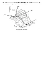
Page 1060: ...Fig 12 ENGINE COMPARTMENT SIDE VIEW 13 6 FRAME BUMPERS LH FRAME Continued ...
Page 1061: ...Fig 13 FORWARD FRAME SECTION AND ENGINE CRADLE LH FRAME BUMPERS 13 7 FRAME Continued ...
Page 1062: ...Fig 14 REAR FRAME SECTION 13 8 FRAME BUMPERS LH FRAME Continued ...
Page 1070: ......
Page 1106: ......
Page 1228: ...Neutral Speed Over 8 mph 21 48 TRANSAXLE LH 42LE AUTOMATIC TRANSAXLE Continued ...
Page 1229: ...Reverse LH TRANSAXLE 21 49 42LE AUTOMATIC TRANSAXLE Continued ...
Page 1231: ...First Gear LH TRANSAXLE 21 51 42LE AUTOMATIC TRANSAXLE Continued ...
Page 1232: ...Second Gear 21 52 TRANSAXLE LH 42LE AUTOMATIC TRANSAXLE Continued ...
Page 1233: ...Second Gear EMCC LH TRANSAXLE 21 53 42LE AUTOMATIC TRANSAXLE Continued ...
Page 1234: ...Direct Gear 21 54 TRANSAXLE LH 42LE AUTOMATIC TRANSAXLE Continued ...
Page 1235: ...Direct Gear EMCC LH TRANSAXLE 21 55 42LE AUTOMATIC TRANSAXLE Continued ...
Page 1236: ...Direct Gear CC On 21 56 TRANSAXLE LH 42LE AUTOMATIC TRANSAXLE Continued ...
Page 1237: ...Overdrive LH TRANSAXLE 21 57 42LE AUTOMATIC TRANSAXLE Continued ...
Page 1238: ...Overdrive EMCC 21 58 TRANSAXLE LH 42LE AUTOMATIC TRANSAXLE Continued ...
Page 1239: ...Overdrive CC On LH TRANSAXLE 21 59 42LE AUTOMATIC TRANSAXLE Continued ...
Page 1252: ...Fig 153 Master Shim Chart 21 72 TRANSAXLE LH BEARINGS Continued ...
Page 1370: ......
Page 1497: ...Fig 11 LOAD BEAM AND COWL AREA LH BODY STRUCTURE 23 127 SEALER LOCATIONS Continued ...
Page 1498: ...Fig 12 BODY SIDE APERTURE 23 128 BODY STRUCTURE LH SEALER LOCATIONS Continued ...
Page 1500: ...Fig 14 FLOOR PAN 23 130 BODY STRUCTURE LH SEALER LOCATIONS Continued ...
Page 1501: ...Fig 15 FLOOR PAN LH BODY STRUCTURE 23 131 SEALER LOCATIONS Continued ...
Page 1502: ...Fig 16 FLOOR PAN 23 132 BODY STRUCTURE LH SEALER LOCATIONS Continued ...
Page 1503: ...Fig 17 REAR TRUNK AREA LH BODY STRUCTURE 23 133 SEALER LOCATIONS Continued ...
Page 1504: ...Fig 18 INNER WHEELHOUSE 23 134 BODY STRUCTURE LH SEALER LOCATIONS Continued ...
Page 1505: ...Fig 19 REAR QUARTER PANE LH BODY STRUCTURE 23 135 SEALER LOCATIONS Continued ...
Page 1506: ...Fig 20 DECKLID 23 136 BODY STRUCTURE LH SEALER LOCATIONS Continued ...
Page 1507: ...Fig 21 FRONT DOORS LH BODY STRUCTURE 23 137 SEALER LOCATIONS Continued ...
Page 1508: ...Fig 22 REAR DOORS 23 138 BODY STRUCTURE LH SEALER LOCATIONS Continued ...
Page 1511: ...Fig 26 ROOF Fig 27 SUNROOF LH BODY STRUCTURE 23 141 STRUCTURAL ADHESIVE LOCATIONS Continued ...
Page 1512: ...Fig 28 DOORS 23 142 BODY STRUCTURE LH STRUCTURAL ADHESIVE LOCATIONS Continued ...
Page 1513: ...Fig 29 DECKLID LH BODY STRUCTURE 23 143 STRUCTURAL ADHESIVE LOCATIONS Continued ...
Page 1516: ...Fig 30 ENGINE COMPARTMENT 23 146 BODY STRUCTURE LH WELD LOCATIONS Continued ...
Page 1517: ...Fig 31 ENGINE COMPARTMENT LH BODY STRUCTURE 23 147 WELD LOCATIONS Continued ...
Page 1518: ...Fig 32 ENGINE COMPARTMENT 23 148 BODY STRUCTURE LH WELD LOCATIONS Continued ...
Page 1519: ...Fig 33 ENGINE COMPARTMENT LH BODY STRUCTURE 23 149 WELD LOCATIONS Continued ...
Page 1520: ...Fig 34 ENGINE COMPARTMENT 23 150 BODY STRUCTURE LH WELD LOCATIONS Continued ...
Page 1521: ...Fig 35 ENGINE COMPARTMENT LH BODY STRUCTURE 23 151 WELD LOCATIONS Continued ...
Page 1522: ...Fig 36 ENGINE COMPARTMENT 23 152 BODY STRUCTURE LH WELD LOCATIONS Continued ...
Page 1523: ...Fig 37 ENGINE COMPARTMENT LH BODY STRUCTURE 23 153 WELD LOCATIONS Continued ...
Page 1524: ...Fig 38 ENGINE COMPARTMENT 23 154 BODY STRUCTURE LH WELD LOCATIONS Continued ...
Page 1525: ...Fig 39 ENGINE COMPARTMENT LH BODY STRUCTURE 23 155 WELD LOCATIONS Continued ...
Page 1526: ...Fig 40 ENGINE COMPARTMENT 23 156 BODY STRUCTURE LH WELD LOCATIONS Continued ...
Page 1527: ...Fig 41 DASH AND COWL LH BODY STRUCTURE 23 157 WELD LOCATIONS Continued ...
Page 1528: ...Fig 42 DASH AND COWL 23 158 BODY STRUCTURE LH WELD LOCATIONS Continued ...
Page 1529: ...Fig 43 DASH AND COWL LH BODY STRUCTURE 23 159 WELD LOCATIONS Continued ...
Page 1530: ...Fig 44 DASH AND COWL 23 160 BODY STRUCTURE LH WELD LOCATIONS Continued ...
Page 1531: ...Fig 45 DASH AND COWL LH BODY STRUCTURE 23 161 WELD LOCATIONS Continued ...
Page 1532: ...Fig 46 DASH AND COWL 23 162 BODY STRUCTURE LH WELD LOCATIONS Continued ...
Page 1533: ...Fig 47 ROOF PANEL AND ROOF BOWS LH BODY STRUCTURE 23 163 WELD LOCATIONS Continued ...
Page 1534: ...Fig 48 ROOF PANEL AND ROOF BOWS 23 164 BODY STRUCTURE LH WELD LOCATIONS Continued ...
Page 1535: ...Fig 49 ROOF PANEL AND ROOF BOWS LH BODY STRUCTURE 23 165 WELD LOCATIONS Continued ...
Page 1537: ...Fig 52 BODY SIDE APERTURE LH BODY STRUCTURE 23 167 WELD LOCATIONS Continued ...
Page 1538: ...Fig 53 BODY SIDE APERTURE 23 168 BODY STRUCTURE LH WELD LOCATIONS Continued ...
Page 1539: ...Fig 54 BODY SIDE APERTURE LH BODY STRUCTURE 23 169 WELD LOCATIONS Continued ...
Page 1540: ...Fig 55 BODY SIDE APERTURE 23 170 BODY STRUCTURE LH WELD LOCATIONS Continued ...
Page 1541: ...Fig 56 BODY SIDE APERTURE LH BODY STRUCTURE 23 171 WELD LOCATIONS Continued ...
Page 1542: ...Fig 57 BODY SIDE APERTURE 23 172 BODY STRUCTURE LH WELD LOCATIONS Continued ...
Page 1543: ...Fig 58 BODY SIDE APERTURE LH BODY STRUCTURE 23 173 WELD LOCATIONS Continued ...
Page 1544: ...Fig 59 BODY SIDE APERTURE 23 174 BODY STRUCTURE LH WELD LOCATIONS Continued ...
Page 1545: ...Fig 60 BODY SIDE APERTURE LH BODY STRUCTURE 23 175 WELD LOCATIONS Continued ...
Page 1546: ...Fig 61 BODY SIDE APERTURE 23 176 BODY STRUCTURE LH WELD LOCATIONS Continued ...
Page 1547: ...Fig 62 BODY SIDE APERTURE LH BODY STRUCTURE 23 177 WELD LOCATIONS Continued ...
Page 1548: ...Fig 63 BODY SIDE APERTURE 23 178 BODY STRUCTURE LH WELD LOCATIONS Continued ...
Page 1549: ...Fig 64 FLOOR PAN LH BODY STRUCTURE 23 179 WELD LOCATIONS Continued ...
Page 1550: ...Fig 65 FLOOR PAN 23 180 BODY STRUCTURE LH WELD LOCATIONS Continued ...
Page 1551: ...Fig 66 FLOOR PAN LH BODY STRUCTURE 23 181 WELD LOCATIONS Continued ...
Page 1552: ...Fig 67 FLOOR PAN 23 182 BODY STRUCTURE LH WELD LOCATIONS Continued ...
Page 1553: ...Fig 68 FLOOR PAN LH BODY STRUCTURE 23 183 WELD LOCATIONS Continued ...
Page 1554: ...Fig 69 FLOOR PAN 23 184 BODY STRUCTURE LH WELD LOCATIONS Continued ...
Page 1555: ...Fig 70 FLOOR PAN LH BODY STRUCTURE 23 185 WELD LOCATIONS Continued ...
Page 1556: ...Fig 71 FLOOR PAN 23 186 BODY STRUCTURE LH WELD LOCATIONS Continued ...
Page 1557: ...Fig 72 FLOOR PAN LH BODY STRUCTURE 23 187 WELD LOCATIONS Continued ...
Page 1558: ...Fig 73 FLOOR PAN 23 188 BODY STRUCTURE LH WELD LOCATIONS Continued ...
Page 1559: ...Fig 74 FLOOR PAN LH BODY STRUCTURE 23 189 WELD LOCATIONS Continued ...
Page 1560: ...Fig 75 FLOOR PAN 23 190 BODY STRUCTURE LH WELD LOCATIONS Continued ...
Page 1561: ...Fig 76 FLOOR PAN LH BODY STRUCTURE 23 191 WELD LOCATIONS Continued ...
Page 1562: ...Fig 77 FLOOR PAN 23 192 BODY STRUCTURE LH WELD LOCATIONS Continued ...
Page 1563: ...Fig 78 FLOOR PAN LH BODY STRUCTURE 23 193 WELD LOCATIONS Continued ...
Page 1564: ...Fig 79 FLOOR PAN Fig 80 FLOOR PAN 23 194 BODY STRUCTURE LH WELD LOCATIONS Continued ...
Page 1565: ...Fig 81 REAR SHELF LH BODY STRUCTURE 23 195 WELD LOCATIONS Continued ...
Page 1566: ...Fig 82 REAR SHELF 23 196 BODY STRUCTURE LH WELD LOCATIONS Continued ...
Page 1567: ...Fig 83 REAR SHELF LH BODY STRUCTURE 23 197 WELD LOCATIONS Continued ...
Page 1568: ......
Page 1640: ......
Page 1670: ......


