


Other vehicle equipped electronic modules that
may affect memory system operation are as follows:
•
Body Control Module (BCM) - Refer to Body
Control Module in Electronic Control Modules for
more information.
•
Electronic
Vehicle
Information
Center
(EVIC) - Refer to Electronic Vehicle Information
Center in Overhead Console for more information.
•
Powertrain Control Module (PCM) - Refer to
Powertrain Control Module in Electronic Control
Modules for more information.
Refer to Heated Seat System for more informa-
tion on the heated seat system.
Refer to Wiring for complete circuit diagrams. Fol-
lowing are general descriptions and operations of the
major components in the power/memory seat sys-
tems.
OPERATION
OPERATION - POWER SEAT SYSTEM
The power seat system receives battery current
through a 40 amp fuse in the Power Distribution
Center (PDC) and a 20 amp circuit breaker in the
junction block so that the power seats remain opera-
tional, regardless of the ignition switch position. See
the owner’s manual in the vehicle glove box for more
information on the features, use and operation of the
power seat system.
OPERATION - MEMORY SEAT SYSTEM
The Memory Heated Seat/Mirror Module receives
hard wired inputs from the memory set/position
switch and the potentiometers, mounted on each of
the driver power seat track motors and the driver
side view mirror motor. The programmed software in
the module allows it to know where the seat/mirror
is located in its designed travel by a resistance read-
ing generated from the seat track or mirror mounted
potentiometer. This way, when the memory switch is
depressed the module will power the seat track or
mirror motors until the correct preset location is
achieved. The module will prevent the seat memory
recall function from being initiated, if the transmis-
sion gear selector lever is not in the Park or Neutral
positions, or if the vehicle is moving. These inputs
are monitored over the PCI data bus circuit by the
MHSMM.
See the owner’s manual in the vehicle glove box for
more information on the features, use and operation
of the memory seat system. Refer to Electronic
Vehicle Information Center in Overhead Console
Systems for information on the EVIC.
DIAGNOSIS AND TESTING
DIAGNOSIS AND TESTING - POWER SEATS
The following tests will help to diagnose the hard
wired components and circuits of the power seat sys-
tem. However, if the vehicle is also equipped with the
optional memory system, these tests may not prove
conclusive in the diagnosis of the driver side power
seat. In order to obtain conclusive testing of the
driver side power seat with the memory system
option, the Programmable Communications Interface
(PCI) data bus network and all of the electronic mod-
ules that provide inputs to, or receive outputs from
the memory system components must be checked.
WARNING: SOME VEHICLES ARE EQUIPPED WITH
SEATBACK
MOUNTED
AIRBAGS.
BEFORE
ATTEMPTING TO DIAGNOSE OR SERVICE ANY
SEAT OR POWER SEAT SYSTEM COMPONENT
YOU MUST FIRST DISCONNECT AND ISOLATE THE
BATTERY NEGATIVE CABLE. THEN WAIT TWO MIN-
UTES FOR THE SYSTEM CAPACITOR TO DIS-
CHARGE BEFORE FURTHER SYSTEM SERVICE.
THIS IS THE ONLY SURE WAY TO DISABLE THE
AIRBAG SYSTEM. FAILURE TO DO SO COULD
RESULT IN ACCIDENTAL AIRBAG DEPLOYMENT
AND POSSIBLE PERSONAL INJURY.
NOTE: Vehicles equipped with the memory/heated
seat option utilize a low voltage cut-off feature. This
feature turns off the 12v power to the power seat
system anytime vehicle voltage is below 11.7v. Be
certain to check the vehicle electrical system for
proper voltage anytime the power seat system
appears inoperational.
The most reliable, efficient, and accurate means to
diagnose the driver side power seat with the memory
system option requires the use of a DRB III
t
scan
tool and the proper Diagnostic Procedures manual.
The DRB III
t
scan tool can provide confirmation that
the PCI data bus is functional, that all of the elec-
tronic modules are sending and receiving the proper
messages on the PCI data bus, and that the memory
system is receiving the proper hard wired inputs and
relaying the proper hard wired outputs to perform its
driver side power seat functions.
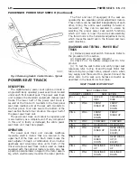
Before any testing of the power seat system is
attempted, the battery should be fully-charged. For
complete circuit diagrams, refer to Power Seat in
the Contents of Wiring Diagrams.
With the dome lamp on, apply the power seat
switch in the direction of the failure. If the dome
lamp dims, the seat may be jamming. Check under
and behind the seat for binding or obstructions. If
LH
POWER SEATS
8N - 13
POWER SEATS (Continued)
Summary of Contents for 2004 Concorde
Page 2: ......
Page 5: ...Fig 3 FASTENER IDENTIFICATION LH INTRODUCTION 3 FASTENER IDENTIFICATION Continued ...
Page 6: ...Fig 4 FASTENER STRENGTH 4 INTRODUCTION LH FASTENER IDENTIFICATION Continued ...
Page 9: ...Fig 6 METRIC CONVERSION CHART LH INTRODUCTION 7 METRIC SYSTEM Continued ...
Page 14: ......
Page 184: ......
Page 226: ......
Page 246: ......
Page 310: ......
Page 316: ......
Page 330: ......
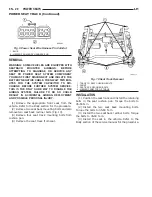
Page 423: ...Fig 1 SIDE AIRBAG LOCATION TYPICAL LH RESTRAINTS 8O 3 RESTRAINTS Continued ...
Page 448: ......
Page 490: ......
Page 506: ......
Page 510: ......
Page 511: ......
Page 512: ......
Page 513: ......
Page 514: ......
Page 515: ......
Page 516: ......
Page 517: ......
Page 518: ......
Page 519: ......
Page 520: ......
Page 521: ......
Page 522: ......
Page 523: ......
Page 524: ......
Page 525: ......
Page 526: ......
Page 527: ......
Page 528: ......
Page 529: ......
Page 530: ......
Page 531: ......
Page 532: ......
Page 533: ......
Page 534: ......
Page 535: ......
Page 536: ......
Page 537: ......
Page 538: ......
Page 540: ......
Page 541: ......
Page 542: ......
Page 543: ......
Page 544: ......
Page 546: ......
Page 547: ......
Page 548: ......
Page 549: ......
Page 550: ......
Page 551: ......
Page 552: ......
Page 553: ......
Page 554: ......
Page 555: ......
Page 556: ......
Page 557: ......
Page 558: ......
Page 559: ......
Page 560: ......
Page 561: ......
Page 562: ......
Page 563: ......
Page 564: ......
Page 565: ......
Page 566: ......
Page 567: ......
Page 568: ......
Page 569: ......
Page 570: ......
Page 571: ......
Page 572: ......
Page 573: ......
Page 574: ......
Page 575: ......
Page 576: ......
Page 577: ......
Page 578: ......
Page 580: ......
Page 581: ......
Page 582: ......
Page 583: ......
Page 584: ......
Page 585: ......
Page 586: ......
Page 587: ......
Page 588: ......
Page 589: ......
Page 590: ......
Page 591: ......
Page 592: ......
Page 593: ......
Page 594: ......
Page 595: ......
Page 596: ......
Page 597: ......
Page 598: ......
Page 599: ......
Page 600: ......
Page 602: ......
Page 603: ......
Page 604: ......
Page 606: ......
Page 607: ......
Page 608: ......
Page 610: ......
Page 612: ......
Page 613: ......
Page 614: ......
Page 615: ......
Page 616: ......
Page 617: ......
Page 618: ......
Page 619: ......
Page 620: ......
Page 621: ......
Page 622: ......
Page 623: ......
Page 624: ......
Page 625: ......
Page 626: ......
Page 627: ......
Page 628: ......
Page 629: ......
Page 630: ......
Page 631: ......
Page 632: ......
Page 633: ......
Page 634: ......
Page 635: ......
Page 636: ......
Page 638: ......
Page 639: ......
Page 640: ......
Page 641: ......
Page 642: ......
Page 643: ......
Page 644: ......
Page 646: ......
Page 647: ......
Page 648: ......
Page 650: ......
Page 651: ......
Page 652: ......
Page 654: ......
Page 655: ......
Page 656: ......
Page 657: ......
Page 658: ......
Page 660: ......
Page 661: ......
Page 662: ......
Page 663: ......
Page 664: ......
Page 665: ......
Page 666: ......
Page 667: ......
Page 668: ......
Page 670: ......
Page 671: ......
Page 672: ......
Page 674: ......
Page 675: ......
Page 676: ......
Page 677: ......
Page 678: ......
Page 679: ......
Page 680: ......
Page 681: ......
Page 682: ......
Page 684: ......
Page 685: ......
Page 686: ......
Page 688: ......
Page 689: ......
Page 690: ......
Page 691: ......
Page 692: ......
Page 693: ......
Page 694: ......
Page 696: ......
Page 697: ......
Page 698: ......
Page 699: ......
Page 700: ......
Page 701: ......
Page 702: ......
Page 703: ......
Page 704: ......
Page 705: ......
Page 706: ......
Page 707: ......
Page 708: ......
Page 709: ......
Page 710: ......
Page 712: ......
Page 713: ......
Page 714: ......
Page 715: ......
Page 716: ......
Page 717: ......
Page 718: ......
Page 719: ......
Page 720: ......
Page 721: ......
Page 722: ......
Page 723: ......
Page 724: ......
Page 726: ......
Page 727: ......
Page 728: ......
Page 730: ......
Page 732: ......
Page 733: ......
Page 734: ......
Page 735: ......
Page 736: ......
Page 737: ......
Page 738: ......
Page 739: ......
Page 740: ......
Page 741: ......
Page 742: ......
Page 743: ......
Page 744: ......
Page 745: ......
Page 746: ......
Page 748: ......
Page 749: ......
Page 750: ......
Page 751: ......
Page 752: ......
Page 753: ......
Page 754: ......
Page 755: ......
Page 756: ......
Page 758: ......
Page 759: ......
Page 760: ......
Page 761: ......
Page 762: ......
Page 764: ......
Page 765: ......
Page 766: ......
Page 767: ......
Page 768: ......
Page 770: ......
Page 771: ......
Page 772: ......
Page 774: ......
Page 775: ......
Page 776: ......
Page 777: ......
Page 778: ......
Page 780: ......
Page 781: ......
Page 782: ......
Page 783: ......
Page 784: ......
Page 785: ......
Page 786: ......
Page 788: ......
Page 789: ......
Page 790: ......
Page 791: ......
Page 792: ......
Page 793: ......
Page 794: ......
Page 796: ......
Page 798: ......
Page 800: ......
Page 801: ......
Page 802: ......
Page 946: ......
Page 956: ...Fig 1 3 5L Engine 9 4 ENGINE LH ENGINE 3 5L Continued ...
Page 1042: ......
Page 1054: ......
Page 1060: ...Fig 12 ENGINE COMPARTMENT SIDE VIEW 13 6 FRAME BUMPERS LH FRAME Continued ...
Page 1061: ...Fig 13 FORWARD FRAME SECTION AND ENGINE CRADLE LH FRAME BUMPERS 13 7 FRAME Continued ...
Page 1062: ...Fig 14 REAR FRAME SECTION 13 8 FRAME BUMPERS LH FRAME Continued ...
Page 1070: ......
Page 1106: ......
Page 1228: ...Neutral Speed Over 8 mph 21 48 TRANSAXLE LH 42LE AUTOMATIC TRANSAXLE Continued ...
Page 1229: ...Reverse LH TRANSAXLE 21 49 42LE AUTOMATIC TRANSAXLE Continued ...
Page 1231: ...First Gear LH TRANSAXLE 21 51 42LE AUTOMATIC TRANSAXLE Continued ...
Page 1232: ...Second Gear 21 52 TRANSAXLE LH 42LE AUTOMATIC TRANSAXLE Continued ...
Page 1233: ...Second Gear EMCC LH TRANSAXLE 21 53 42LE AUTOMATIC TRANSAXLE Continued ...
Page 1234: ...Direct Gear 21 54 TRANSAXLE LH 42LE AUTOMATIC TRANSAXLE Continued ...
Page 1235: ...Direct Gear EMCC LH TRANSAXLE 21 55 42LE AUTOMATIC TRANSAXLE Continued ...
Page 1236: ...Direct Gear CC On 21 56 TRANSAXLE LH 42LE AUTOMATIC TRANSAXLE Continued ...
Page 1237: ...Overdrive LH TRANSAXLE 21 57 42LE AUTOMATIC TRANSAXLE Continued ...
Page 1238: ...Overdrive EMCC 21 58 TRANSAXLE LH 42LE AUTOMATIC TRANSAXLE Continued ...
Page 1239: ...Overdrive CC On LH TRANSAXLE 21 59 42LE AUTOMATIC TRANSAXLE Continued ...
Page 1252: ...Fig 153 Master Shim Chart 21 72 TRANSAXLE LH BEARINGS Continued ...
Page 1370: ......
Page 1497: ...Fig 11 LOAD BEAM AND COWL AREA LH BODY STRUCTURE 23 127 SEALER LOCATIONS Continued ...
Page 1498: ...Fig 12 BODY SIDE APERTURE 23 128 BODY STRUCTURE LH SEALER LOCATIONS Continued ...
Page 1500: ...Fig 14 FLOOR PAN 23 130 BODY STRUCTURE LH SEALER LOCATIONS Continued ...
Page 1501: ...Fig 15 FLOOR PAN LH BODY STRUCTURE 23 131 SEALER LOCATIONS Continued ...
Page 1502: ...Fig 16 FLOOR PAN 23 132 BODY STRUCTURE LH SEALER LOCATIONS Continued ...
Page 1503: ...Fig 17 REAR TRUNK AREA LH BODY STRUCTURE 23 133 SEALER LOCATIONS Continued ...
Page 1504: ...Fig 18 INNER WHEELHOUSE 23 134 BODY STRUCTURE LH SEALER LOCATIONS Continued ...
Page 1505: ...Fig 19 REAR QUARTER PANE LH BODY STRUCTURE 23 135 SEALER LOCATIONS Continued ...
Page 1506: ...Fig 20 DECKLID 23 136 BODY STRUCTURE LH SEALER LOCATIONS Continued ...
Page 1507: ...Fig 21 FRONT DOORS LH BODY STRUCTURE 23 137 SEALER LOCATIONS Continued ...
Page 1508: ...Fig 22 REAR DOORS 23 138 BODY STRUCTURE LH SEALER LOCATIONS Continued ...
Page 1511: ...Fig 26 ROOF Fig 27 SUNROOF LH BODY STRUCTURE 23 141 STRUCTURAL ADHESIVE LOCATIONS Continued ...
Page 1512: ...Fig 28 DOORS 23 142 BODY STRUCTURE LH STRUCTURAL ADHESIVE LOCATIONS Continued ...
Page 1513: ...Fig 29 DECKLID LH BODY STRUCTURE 23 143 STRUCTURAL ADHESIVE LOCATIONS Continued ...
Page 1516: ...Fig 30 ENGINE COMPARTMENT 23 146 BODY STRUCTURE LH WELD LOCATIONS Continued ...
Page 1517: ...Fig 31 ENGINE COMPARTMENT LH BODY STRUCTURE 23 147 WELD LOCATIONS Continued ...
Page 1518: ...Fig 32 ENGINE COMPARTMENT 23 148 BODY STRUCTURE LH WELD LOCATIONS Continued ...
Page 1519: ...Fig 33 ENGINE COMPARTMENT LH BODY STRUCTURE 23 149 WELD LOCATIONS Continued ...
Page 1520: ...Fig 34 ENGINE COMPARTMENT 23 150 BODY STRUCTURE LH WELD LOCATIONS Continued ...
Page 1521: ...Fig 35 ENGINE COMPARTMENT LH BODY STRUCTURE 23 151 WELD LOCATIONS Continued ...
Page 1522: ...Fig 36 ENGINE COMPARTMENT 23 152 BODY STRUCTURE LH WELD LOCATIONS Continued ...
Page 1523: ...Fig 37 ENGINE COMPARTMENT LH BODY STRUCTURE 23 153 WELD LOCATIONS Continued ...
Page 1524: ...Fig 38 ENGINE COMPARTMENT 23 154 BODY STRUCTURE LH WELD LOCATIONS Continued ...
Page 1525: ...Fig 39 ENGINE COMPARTMENT LH BODY STRUCTURE 23 155 WELD LOCATIONS Continued ...
Page 1526: ...Fig 40 ENGINE COMPARTMENT 23 156 BODY STRUCTURE LH WELD LOCATIONS Continued ...
Page 1527: ...Fig 41 DASH AND COWL LH BODY STRUCTURE 23 157 WELD LOCATIONS Continued ...
Page 1528: ...Fig 42 DASH AND COWL 23 158 BODY STRUCTURE LH WELD LOCATIONS Continued ...
Page 1529: ...Fig 43 DASH AND COWL LH BODY STRUCTURE 23 159 WELD LOCATIONS Continued ...
Page 1530: ...Fig 44 DASH AND COWL 23 160 BODY STRUCTURE LH WELD LOCATIONS Continued ...
Page 1531: ...Fig 45 DASH AND COWL LH BODY STRUCTURE 23 161 WELD LOCATIONS Continued ...
Page 1532: ...Fig 46 DASH AND COWL 23 162 BODY STRUCTURE LH WELD LOCATIONS Continued ...
Page 1533: ...Fig 47 ROOF PANEL AND ROOF BOWS LH BODY STRUCTURE 23 163 WELD LOCATIONS Continued ...
Page 1534: ...Fig 48 ROOF PANEL AND ROOF BOWS 23 164 BODY STRUCTURE LH WELD LOCATIONS Continued ...
Page 1535: ...Fig 49 ROOF PANEL AND ROOF BOWS LH BODY STRUCTURE 23 165 WELD LOCATIONS Continued ...
Page 1537: ...Fig 52 BODY SIDE APERTURE LH BODY STRUCTURE 23 167 WELD LOCATIONS Continued ...
Page 1538: ...Fig 53 BODY SIDE APERTURE 23 168 BODY STRUCTURE LH WELD LOCATIONS Continued ...
Page 1539: ...Fig 54 BODY SIDE APERTURE LH BODY STRUCTURE 23 169 WELD LOCATIONS Continued ...
Page 1540: ...Fig 55 BODY SIDE APERTURE 23 170 BODY STRUCTURE LH WELD LOCATIONS Continued ...
Page 1541: ...Fig 56 BODY SIDE APERTURE LH BODY STRUCTURE 23 171 WELD LOCATIONS Continued ...
Page 1542: ...Fig 57 BODY SIDE APERTURE 23 172 BODY STRUCTURE LH WELD LOCATIONS Continued ...
Page 1543: ...Fig 58 BODY SIDE APERTURE LH BODY STRUCTURE 23 173 WELD LOCATIONS Continued ...
Page 1544: ...Fig 59 BODY SIDE APERTURE 23 174 BODY STRUCTURE LH WELD LOCATIONS Continued ...
Page 1545: ...Fig 60 BODY SIDE APERTURE LH BODY STRUCTURE 23 175 WELD LOCATIONS Continued ...
Page 1546: ...Fig 61 BODY SIDE APERTURE 23 176 BODY STRUCTURE LH WELD LOCATIONS Continued ...
Page 1547: ...Fig 62 BODY SIDE APERTURE LH BODY STRUCTURE 23 177 WELD LOCATIONS Continued ...
Page 1548: ...Fig 63 BODY SIDE APERTURE 23 178 BODY STRUCTURE LH WELD LOCATIONS Continued ...
Page 1549: ...Fig 64 FLOOR PAN LH BODY STRUCTURE 23 179 WELD LOCATIONS Continued ...
Page 1550: ...Fig 65 FLOOR PAN 23 180 BODY STRUCTURE LH WELD LOCATIONS Continued ...
Page 1551: ...Fig 66 FLOOR PAN LH BODY STRUCTURE 23 181 WELD LOCATIONS Continued ...
Page 1552: ...Fig 67 FLOOR PAN 23 182 BODY STRUCTURE LH WELD LOCATIONS Continued ...
Page 1553: ...Fig 68 FLOOR PAN LH BODY STRUCTURE 23 183 WELD LOCATIONS Continued ...
Page 1554: ...Fig 69 FLOOR PAN 23 184 BODY STRUCTURE LH WELD LOCATIONS Continued ...
Page 1555: ...Fig 70 FLOOR PAN LH BODY STRUCTURE 23 185 WELD LOCATIONS Continued ...
Page 1556: ...Fig 71 FLOOR PAN 23 186 BODY STRUCTURE LH WELD LOCATIONS Continued ...
Page 1557: ...Fig 72 FLOOR PAN LH BODY STRUCTURE 23 187 WELD LOCATIONS Continued ...
Page 1558: ...Fig 73 FLOOR PAN 23 188 BODY STRUCTURE LH WELD LOCATIONS Continued ...
Page 1559: ...Fig 74 FLOOR PAN LH BODY STRUCTURE 23 189 WELD LOCATIONS Continued ...
Page 1560: ...Fig 75 FLOOR PAN 23 190 BODY STRUCTURE LH WELD LOCATIONS Continued ...
Page 1561: ...Fig 76 FLOOR PAN LH BODY STRUCTURE 23 191 WELD LOCATIONS Continued ...
Page 1562: ...Fig 77 FLOOR PAN 23 192 BODY STRUCTURE LH WELD LOCATIONS Continued ...
Page 1563: ...Fig 78 FLOOR PAN LH BODY STRUCTURE 23 193 WELD LOCATIONS Continued ...
Page 1564: ...Fig 79 FLOOR PAN Fig 80 FLOOR PAN 23 194 BODY STRUCTURE LH WELD LOCATIONS Continued ...
Page 1565: ...Fig 81 REAR SHELF LH BODY STRUCTURE 23 195 WELD LOCATIONS Continued ...
Page 1566: ...Fig 82 REAR SHELF 23 196 BODY STRUCTURE LH WELD LOCATIONS Continued ...
Page 1567: ...Fig 83 REAR SHELF LH BODY STRUCTURE 23 197 WELD LOCATIONS Continued ...
Page 1568: ......
Page 1640: ......
Page 1670: ......


