

7
Note: All electrical wiring must be done according to
National Electrical and local codes by a qualified per-
son.
ELECTRIC SHOCK HAZARD. Any installation
involving electric heaters must be performed
by a qualified person and must be effective-
ly grounded in accordance with the National
Electrical Code to eliminate shock hazard.
The system designer is responsible for the
safety of this equipment and should install ad-
equate back-up controls and safety devices
with their electric heating equipment. Where
the consequences of failure could result in per-
sonal injury or property damage, back-up con-
trols are essential.
1. Check all factory wiring for loose connections. It is
possible for connections to become loose during
shipping.
2. Connect heater according to the voltage and fre-
quency specified on the nameplate.
3. Heaters are not provided with a control switch and
may be controlled by a wall-mounted thermostat.
4. All units are provided with control and power termi-
nal blocks for customer’s connection.
5. Protection against overheating is provided by an
internal automatic thermal cutout (manual reset
cutout optional) which opens the electric circuit if
the normal air-flow is restricted or stopped. Cutout
automatically energizes heater on removal of the
obstruction. If optional manual reset is tripped, de-
termine cause before re-energizing.
6. Heaters rated 5kW - 39kW are equipped with fan
delay control.
This control continues fan operation for a short time
after elements are de-energized to dissipate residu-
al heat.
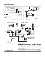
7. Follow wiring diagram label located on door inside
control panel.
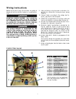
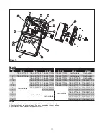
Wiring Instructions
Control Panel Layout
A
B
G
F
C
D
E
I
H
J
Letter
Description
A
Thermostat
B
Power Contactor
C
Fan Relay
D
Terminal Block
E
Motor Contactor
F
Grounding Lug
G
Conduit Opening
H
Fan Only Switch
I
Pilot Light
J
Transformer (Hidden)
The Transformer (J) is located below
the motor contactor (E), therefore it is
not seen in photo.