background image

Manual Operation 


3-89 


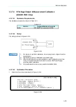
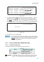
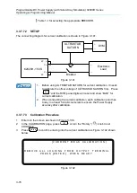
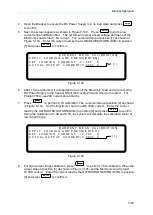
Figure 3-160 


3.3.9.3 

SAS MODE 

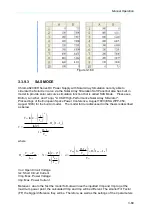
Chroma 62000H Series DC Power Supply with Solar Array Simulation not only able to 
simulate the Solar Cell curve via the Solar Array Simulation Soft Panel but also has built in 
model to provide solar cell curve simulation function that is called SAS Mode.    Please see 
Britton, Lunscher, and Tanju, "A 9 KW High-Performance Solar Array Simulator", 
Proceedings of the European Space Power Conference, August 1993 (ESA WPP-054, 
August 1993) for the built-in model.    The model formula discussed in the thesis is described 
as below. 
 

 

oc

sc

s

sc

s

N

sc

oc

V

I

R

I

I

R

I

I

V

V






1

2

ln

2

ln


where 
 

mp

mp

oc

s

I

V

V

R






sc

m p

a

I

I

N

ln

2

2

ln


oc

sc

mp

s

oc

sc

s

mp

V

I

I

R

V

I

R

V

a





1


Voc: Open Circuit Voltage 
Isc: Short Circuit Current 
Vmp: Max. Power Voltage 
Imp: Max. Power Current 
 
Moreover, due to the fact the model formula will use the inputted Vmp and Imp to get the 
maximum power point, the calculated Vmp and Imp will be different. The smaller Fill Factor 
(FF) the bigger difference they will be. Therefore, as well as the settings of the 4 parameters 

Summary of Contents for 62000H Series

Page 1: ...Programmable DC Power Supply with Solar Array Simulation 62000H Series Operating Programming Manual ...

Page 2: ......

Page 3: ...Programmable DC Power Supply with Solar Array Simulation 62000H Series Operating Programming Manual Version 1 7 March 2015 ...

Page 4: ...ma ATE INC shall not be held liable for errors contained herein or direct indirect special incidental or consequential damages in connection with the furnishing performance or use of this material CHROMA ATE INC 66 Huaya 1st Road Guishan Taoyuan 33383 Taiwan Copyright Notices Copyright 2010 Chroma ATE INC all rights reserved Reproduction adaptation or translation of this document without prior wri...

Page 5: ...s or operations repairs will be billed at cost Chroma assumes no responsibility for its product being used in a hazardous or dangerous manner either alone or in conjunction with other equipment High voltage used in some instruments may be dangerous if misused Special disclaimers apply to these instruments Chroma assumes no liability for secondary charges or consequential damages and in any event C...

Page 6: ... the standards of SJ T 11363 2006 and EU 2005 618 EC indicates that the level of the specified chemical substance exceeds the threshold level specified in the standards of SJ T 11363 2006 and EU 2005 618 EC Disposal Do not dispose of electrical appliances as unsorted municipal waste use separate collection facilities Contact your local government for information regarding the collection systems av...

Page 7: ...ansitioned to lead free solder assembly at this moment however most of the components used are RoHS compliant 2 The environment friendly usage period of the product is assumed under the operating environment specified in each product s specification Disposal Do not dispose of electrical appliances as unsorted municipal waste use separate collection facilities Contact your local government for info...

Page 8: ...vi ...

Page 9: ... protective grounding wire or disconnect the wiring of protective grounding terminal Doing so will cause a potential shock hazard that may bring injury to a person FUSES Only fuses with the required rated current voltage and specified type normal blow time delay etc should be used Do not use repaired fuses or short circuited fuse holders To do so could cause a shock or fire hazard DO NOT OPERATE I...

Page 10: ...ound is not explicitly stated This symbol indicates the power connector does not provide grounding Frame or chassis To identify a frame or chassis terminal Alternating Current AC Direct Current DC Alternating Current AC Direct Current DC Push on Push off power switch WARNING The WARNING sign highlights an essential operating or maintenance procedure practice condition statement etc which if not st...

Page 11: ...cation TRIG command to SAS Subsystem Update the following in the chapter of Overview Specification of 62150H 1000S The figure of front panel of 62000H with Solar Array Simulation and main power switch Nov 2011 1 3 Add A620028 and A620027 SLAVE models in the manual Aug 2012 1 4 Update the following Description in Specification section Value of minimum output voltage in Other Specifications section ...

Page 12: ......

Page 13: ...Connection of Remote Sensing Wire Polarity 2 7 2 5 Output Connection 2 7 2 5 1 Rear Panel Output 2 7 2 5 2 Specification of Connecting Wire 2 10 2 5 3 Specification of Parallel Capacitance 2 10 2 5 4 Installing the Handle 62150H for example 2 11 2 6 Power On Procedure 2 11 3 Manual Operation 3 1 3 1 Introduction 3 1 3 2 Setting Voltage Current 3 1 3 3 Setting Configuration 3 2 3 3 1 SYSTEM SETUP 3...

Page 14: ...otection 3 55 3 3 5 16 MATCH Warning 3 56 3 3 6 FACTORY SETTING 3 56 3 3 7 CALIBRATION 3 57 3 3 7 1 Voltage Output Measurement Calibration 3 60 3 3 7 2 Current Measurement Calibration 3 62 3 3 7 3 Current Output PROG Calibration 3 66 3 3 7 4 APG Voltage Calibration 3 69 3 3 7 5 APG Current Calibration 3 72 3 3 7 6 IV Voltage Output Measurement Calibration 62020H 150S Only 3 75 3 3 7 7 IV Current C...

Page 15: ...21 4 3 2 Setting IV Sequence 4 22 4 3 2 1 Setting Sequence Number 4 22 4 3 2 2 Setting IV FILE Number 4 23 4 3 2 3 Setting Sequence Type 4 23 4 3 2 4 Setting Time 4 24 4 3 3 Execution of IV PROGRAM 4 25 4 3 3 1 Running IV PROGRAM 4 25 4 3 3 2 IV Program Main Screen 4 26 5 Remote Operation 5 1 5 1 Overview 5 1 5 1 1 USB Interface 5 1 5 1 2 Setting GPIB Ethernet RS 232C RS 485 Parameters 5 1 5 1 3 C...

Page 16: ...em 5 37 5 6 2 7 IV Subsystem 5 42 5 6 2 8 SAS Subsystem 5 46 5 6 2 9 OUTPUT Subsystem 5 49 5 6 2 10 SYSTEM Subsystem 5 51 6 Theory of Operation 6 1 6 1 Overview 6 1 6 2 Function Description 6 3 6 2 1 I P PFC Stage 6 3 6 2 2 Auxiliary Power 6 4 6 2 3 Output Stage 6 4 6 2 4 Digital Circuit 6 4 7 ETHERNET Functions 62020H 150S Only 7 1 7 1 Usage of Web Page 7 1 7 1 1 Home Page index html 7 1 7 1 2 Co...

Page 17: ... variation 6 Editing mode Programming Mode for output waveform provides multiple output voltage and current combinations in real time for long period test 7 Rotary knob and keyboard control on the front panel to set the output voltage and current 8 VFD panel gives users a high brightness and wide view angle interface for operation 9 Via GPIB Ethernet option USB RS 232 RS 485 or APG analog programm...

Page 18: ...source and resistance that adjusted for the panel setting 3 Remote inhibit control signal TTL 1 2 5 Measuring Editing 1 Measurement for voltage current and power 2 10 programs and 100 sequences to edit voltage current waveform output 3 One run time voltage program that can be set for long hour 4 10 programs and 100 sequences to edit I V curve waveform output 1 3 Specifications Chroma 62000H Series...

Page 19: ...put Noise Ripple Voltage Noise P P 4 450 mV 1500 mV 1500 mV 1500 mV Voltage Ripple rms 65 mV 650 mV 650 mV 650 mV Current Ripple rms 5 80 mA 150 mA 300 mA 450 mA Programming Response Time Rise Time 50 F S CC Load 10ms 6 66A loading 30 ms 30 ms 30 ms Rise Time No Load 10ms 30 ms 30 ms 30 ms Fall Time 50 F S CC Load 10ms 6 66A loading 30 ms 30 ms 30 ms Fall Time 10 F S CC Load 83ms 1 33A loading 100...

Page 20: ...pple Voltage Noise P P 4 2550 mV 1500 mV 2550 mV Voltage Ripple rms 1950 mV 650 mV 1950 mV Current Ripple rms 5 270mA 450mA 270mA Programming Response Time Rise Time 50 F S CC Load 25 ms 30ms 25ms Rise Time No Load 25 ms 30ms 25ms Fall Time 50 F S CC Load 25 ms 30ms 25ms Fall Time 10 F S CC Load 80 ms 100ms 80ms Fall Time No Load 3 s 1 2s 3s Slew Rate Control Voltage slew rate range6 0 001V ms 40V...

Page 21: ...r a 50 to 100 or 100 to 50 load change 1A us Programming Measurement Resolution 62000H 600S 62020H 150S 62000H 1000S Voltage Front Panel 10 mV 100mV Current Front Panel 1 mA 1mA Voltage Digital Interface 0 002 of Vmax Current Digital Interface 0 002 of Imax Voltage Analog Interface 0 04 of Vmax Current Analog Interface 0 04 of Imax Remote Interface Analog programming Standard with Isolated USB Sta...

Page 22: ... P TTL Active Low Analog Interface Accuracy Measurement Voltage 0 5 of F S Current 0 75 of F S Series Parallel Operation16 Master Slave control via CAN for 10 units up to 150KW Series two units Parallel ten units Master Slave control via CAN for 10 units up to 20KW Series two units Parallel ten units for 62020H 150S Auto Sequencing List mode Number of program 10 Number of sequence 100 Dwell time R...

Page 23: ...62020H 150S Operating Temperature Rage 0 C 40 C Storage Temperature Rage 40 C 85 C Approval CE Table 1 3 A620027 A620028 Slave Other Specifications Model A620027 A620028 Slave Unit 15kW Line Regulation8 Voltage 0 01 F S Current 0 05 F S Load Regulation9 Voltage 0 05 F S Current 0 1 F S OVP Adjustment Range Range 0 110 programmable from front panel remote digital inputs Accuracy 1 of full scale out...

Page 24: ...n there is output and the voltage as well as the current setting is larger than the one specified in Note 1 and the load current is 40 over Imax When the output is connected to capacitor the voltage slew rate will decrease if the capacitance is increased 7 This setting is valid only when the load voltage is larger than the one specified in Note 1 The factory default is INF Be sure to adjust the sl...

Page 25: ...t from backwash and damage the device interior see Figure 1 1 2 For switchable power load applications if the output load cable is longer 20cm it is suggested to strand the load cable and parallel the capacitance at the load power input to prevent any unexpected oscillation from occurring see Figure 1 2 3 For load application it can parallel connect the capacitor more than 100uF to the load input ...

Page 26: ...50H 600S 1200 62100H 600S 1200 62150H 600S 1200 62150H 1000S 1200 A620028 1200 A620027 1200 If the voltage exceeds the above range it may result damage to the DC Power Supply 1 4 Function Keys 1 4 1 Front Panel Figure 1 3 Front Panel of 62000H with Solar Array Simulation Figure 1 4 Front Panel of Slave Model A620027 A620028 ...

Page 27: ... key to skip to Program Function Page for setting waveform editing mode 6 LOCAL LOCAL Key Press this key to switch the control mode from remote control back to manual operating mode 7 ENTER ENTER Key Press this key to confirm the parameter settings 8 DEL Delete Key Press this key to delete the input value 9 EXIT EXIT Key Press this key to go to previous screen If this key is pressed before SAVE is...

Page 28: ...nob The user can turn the knob to input data or select an item 17 Main Power Switch It switches the power on or off 18 Rack Bracket Option Use the left right bracket to fix the Power Supply on the Rack 19 LED on Slave Model When the slave model is on the LED varies with its status The green light indicates POWER ON the yellow light indicates the data is transmitting or communication is normal whil...

Page 29: ...ote Sense Connector Connecting this connector to load can compensate the voltage drop generated due to cable resistance Be sure to connect the remote sense connector to the positive output terminal and connector to the negative output terminal Do not connect the remote sense connector to the output terminal reversely 7 Current Sharing Connector It shares the output current equally when connecting ...

Page 30: ...rating Programming Manual 1 14 The callout 8 in Figure 1 6 is the cover plate for standard configuration When GPIB ETHERNET interface is selected as shipping default it will be installed before shipment as Figure 1 9 a b shows a GPIB Interface b ETHERNET Interface Figure 1 9 ...

Page 31: ...age be found contact Chroma RMA immediately to request return shipment Figure 2 1 a b c d e f g and h are the accessories except 62020H 150S except 62020H 150S a cable for current sharing b cable for system bus c cable for A B type USB d cable for analog e terminator for system bus f hoop g cable for Current sharing h cable for System bus Figure 2 1 ...

Page 32: ...h wipe it with volatile liquid such as Cleaning Naphtha Do not use any corrosive liquid to avoid damaging the chassis Use a damp cloth with soap water or soft detergent to clean the LCD front panel For internal cleaning use a low pressure air gun for the dust inside or send it back to our agent for cleaning 2 2 Preparation for Use 1 Remove the iron holder of the front panel as Figure 2 2 shows and...

Page 33: ...ent of each phase 380 400 22A 37 A 50 A 440 480 19A 32 A 44 A 200 240 15 2 A 2 3 2 Input Connection 1 The input connector board is located at the right of the rear panel 2 The power line must be 85 C rated at least 3 The power cable width must be within 6AWG 8AWG Note 10AWG 12AWG is required for Model 62020H 150S 4 See Figure 2 3 a b to assemble 62000H and Figure 2 5 to assemble Model 62020H 150S ...

Page 34: ... cover latch and safety cover to prevent the cable from falling or the electric terminal from exposing a b Figure 2 3 Figure 2 4 1 Connect the green or green yellow metal wire to terminal 2 Connect the black or brown metal wire to L1 L2 L3 terminal 3 Figure 2 5 shows the suggested specification of O type terminal Figure 2 5 ...

Page 35: ... Be sure to select an appropriate withstand voltage cable based on the varied input voltage 2 To ensure the safe operation follow the input power source during installation to select the current rated BREAKER that closes to each phase and connect it to the input terminal in series Table 2 1 is the cable specification of PVC 105 C with the ambient temperature at 30 C for reference Table 2 1 PVC 105...

Page 36: ...of load to the remote sensing connector on the rear panel The connecting wire diameter must be larger than 30AWG and its withstand voltage should be within the specification 3 Though remote sensing is able to compensate the voltage drop however if the line loss is too large see specification it will cause protection on remote sensing as Figure 2 8 shows and is unable to compensate voltage drop cor...

Page 37: ...wer Supply CAUTION 1 When there is voltage existed on the device output please avoid connecting Remote sense to the device output or UUT reversely as it may cause the hardware to blow up 2 The voltage of Remote sensing and local output should be less than 10 V_MAX to prevent the device from blowing up 3 If the Remote sense wire fell off it could cause output voltage to overshoot Be sure to install...

Page 38: ...bare portion is about 1cm and use an O type terminal to crimp it b Secure the power cable and input terminal with a Phillips screwdriver c Secure the safety cover latch and safety cover to prevent the cable from falling or the electric terminal from exposing 4 A standard hoop is attached when purchasing the A620028 or A620027 SLAVE model to fix the current sharing cables as shown in Figure 2 10 Mo...

Page 39: ... The diameter of the wire connected to load must be able to carry the maximum current applied 3 It is no need to use the 62020H 150S 9PIN current sharing cable when using the device as a standalone WARNING For safety reason do not exceed rated current different from 62000H Series for the output current to avoid any danger ...

Page 40: ...480Vac and A620028 380 400Vac 440 480Vac can up to 2mH It can be identified by the sticker labeled 2mH on top of the output cover as Figure 2 12 shows For other models with the needs please contact Chroma s agent 2 Do not use the wire with extra thin diameter to avoid overheating and causing hazard Figure 2 12 2 5 3 Specification of Parallel Capacitance The parallel capacitance for output varies w...

Page 41: ...on the power switch on front panel The DC Power Supply will run a series of self tests The VFD on the front panel will light up and show as below S E L F T E S T Figure 2 14 Meanwhile the DC Power Supply will run self tests for memory data and communication Once the routine of self tests are done the model no and serial no will show on the screen and prompt OK at the right of the test item if pass...

Page 42: ...to the MAIN PAGE automatically as shown below V 0 0 0_ V I 0 0 0 A O F F 0 0 0 0 0 V 0 0 0 0 0 A 0 0 W Figure 2 16 WARNING The DC Power Supply internal circuit may not be able to reset if it is powered off and on immediately It is suggested to wait for 3 seconds after powered off and power it on again CAUTION Before turning on the instrument all protective grounding terminals extension cord and de...

Page 43: ...numeric keys 1 9 to set the value and press ENTER to complete the voltage setting or turn the Rotary knob to adjust the set value 3 Press ON OFF to output the set voltage Please note that in order to remain in CV mode the current setting must be larger than the load current otherwise the output voltage will not be equal to the set voltage Method 2 1 Press VOLT the cursor for V on MAIN PAGE blinks ...

Page 44: ...ng GPIB address 2 Output Setup To set various output parameters including voltage current slew rate etc 3 Series Parallel To set the parameters for series or parallel mode 4 Display To set the parameter arrangement on panel 5 Protection To set the parameters for each protection function 6 Factory Setting To set the production information and settings 7 Calibration To calibrate the DC Power Supply ...

Page 45: ...o select the item to be set 2 Press ENTER to confirm 3 Press EXIT to return to the MAIN PAGE 1 To cancel the setting press EXIT to return to the MAIN PAGE 2 Press VOLT or CURR in any page to return to the MAIN PAGE Figure 3 4 shows the tree structure of CONFIG PAGE ...

Page 46: ...Programmable DC Power Supply with Solar Array Simulation 62000H Series Operating Programming Manual 3 4 Figure 3 4 ...

Page 47: ...s described below 1 Use keys to move the cursor to the column to be set as Figure 3 6 shows S Y S T E M S E T U P A P G V S E T N O N E _ A P G I S E T N O N E A P G V M E A S N O N E A P G I M E A S N O N E B U Z Z E R O N P O W E R O N S T A T U S D E F A U L T Figure 3 6 2 For APG VSET use the numeric keys 0 4 or Rotary to set the mode There are 5 selections for APG VSET which are NONE Vref 0 5...

Page 48: ... Vref 0 5V It means using the power supply output voltage source as the measurement result Vref 0 10V It means using the power supply output voltage source as the measurement result Iref 4 20mA It means using the power supply output current source as the measurement result 7 Press ENTER to confirm 8 For APG IMEAS use the numeric keys 0 3 or Rotary to set the mode There are 4 selections for APG IME...

Page 49: ...V 25A a b DC SOURCE SET 600V 25A APG INPUT 4 20mA DC SOURCE SET APG INPUT 5KOhm 600V 25A c d Figure 3 7 2 APG VMEAS APG IMEAS has 4 selections which are NONE Vref 0 5V Vref 0 10V Iref 4 20mA where a When selecting Vref 5V it means the DC Power Supply s measurement output 0 600V 0A 25A will map to 0 5V as Figure 3 8 a shows b When selecting Vref 10V it means the DC Power Supply s measurement output...

Page 50: ...rate the APG settings and measurements first 4 When setting the APG VMEAS APG IMEAS to Iref 4 20mA mode to ensure the DC Power Supply can output correctly the series resistance cannot exceed 500Ω Also it is necessary to attention to the resistor wattage to avoid damaging the resistor 3 3 1 1 1 Pin Assignment of APG Control APG control is an output of external analog signal and its connector is loc...

Page 51: ...A from this pin to APIGND that can control the output voltage CV mode linearly 4 Voltage programming It inputs the analog voltage 0 10Vdc or 0 5Vdc from this pin to APIGND that can control the output voltage CV mode linearly 5 Voltage measurement This pin will output the voltage in analog signal 4mA 20mA for users to monitor it 6 Voltage measurement This pin will output the voltage in analog signa...

Page 52: ...er It can be turned off if it is not necessary The default is ON 1 Use keys to move the cursor to the column to be set as Figure 3 11 shows S Y S T E M S E T U P A P G V S E T N O N E _ A P G I S E T N O N E A P G V M E A S N O N E A P G I M E A S N O N E B U Z Z E R O N P O W E R O N S T A T U S D E F A U L T Figure 3 11 2 Use the numeric keys 0 1 or Rotary knob to select ON or OFF mode 3 Press E...

Page 53: ...hen it is set to LAST TURN OFF STATUS the instrument will log the command voltage command current and output state before powering it off so that the state before powered off can be obtained for next power on Ex In Figure 3 13 the voltage setting is 60 00V current setting is 10 00A and output setting is ON When it powers on again the instrument will return to the previous state by setting the volt...

Page 54: ...I N I T I O N _ V 6 0 0 0 V 1 0 0 0 A O U T P U T O F F Figure 3 14 3 Press ENTER to confirm 4 Press EXIT to return to the MAIN PAGE 3 3 2 OUTPUT SETUP 1 In Config Setup page press 2 key and ENTER to enter into the Output Setup screen as Figure 3 15 shows 2 Press 3 Press keys to move the cursor to the column to be set 4 Press EXIT to return to the MAIN PAGE Figure 3 15 The values in Figure 3 15 ar...

Page 55: ...ly allows setting the voltage within the range of MIN value user defined value MAX value As example use the 62150H 600S the V LIMIT MAX 100V MIN 20V If the setting exceeds the output voltage 110V set by the user the BUZZER will beep one time if BUZZER is set to ON and the main screen will prompt a warning message automatically as shown in Figure 3 17 below V 6 0 0 0 V I 1 0 0 0 _ A O F F 0 0 0 0 0...

Page 56: ...d to set the output current the DC Power Supply allows setting the current within the range of MIN value user defined value MAX value As example use the 62150H 600S the V LIMIT MAX 20A MIN 2A If the setting exceeds the output current 21A set by the user the BUZZER will beep one time if BUZZER is set to ON and the main screen will prompt a warning message automatically as shown in Figure 3 19 below...

Page 57: ...S the output voltage slew rate of the DC Power Supply is set as Figure 3 21 shows The maximum input Slew Rate is 20V mS and the minimum is 0 001V mS The output of DC Power Supply will use the slew rate to rise to the set output voltage while the fall slew rate is limited by load Vo Time mS Δ T Δ V V SR T Figure 3 21 3 Press ENTER to confirm 4 Press EXIT to return to the MAIN PAGE The minimum trans...

Page 58: ... by 62150H 600S the output current slew rate of the DC Power Supply is set as Figure 3 23 shows The maximum input Slew Rate is 0 1A mS and the minimum is 0 003A mS If the input is larger than 0 3A mS the current Slew Rate will be set to INF and change with maximum slew rate near infinite The output of DC Power Supply will use the slew rate to rise to the set output current Δ T Δ I I SR T Time mS I...

Page 59: ...0 DCOUT_ON of ANALOG INTERFACE on the rear panel will turn to HIGH and when the DC power supply output is OFF the pin10 DCOUT_ON of ANALOG INTERFACE on the rear panel will turn to LOW for other purpose use VDC_R VDC_F t VO DC_ON Figure 3 24 Set DC_ON as described below 1 For the first setting use keys to move the cursor to the column to be set as Figure 3 25 shows Figure 3 25 2 Use the numeric 0 9...

Page 60: ... SAS mode and IV Program O U T P U T S E T U P I V C U R V E P A R A M E T E R C O N T R O L M O D E C C M O D E _ I N P U T F I L T E R 1 0 0 0 Hz O U T P U T S P E E D M I D D L E S E T T I N G M A R G I N 3 Figure 3 27 3 3 2 6 1 Setting CONTROL MODE When the DC Power Supply is operating in IV mode the CONTROL MODE will affect the IV Curve settings and the measured object When set to CC mode the...

Page 61: ...UT FILTER INPUT FILTER is to filter the measured signals for IV Curve calculation used in IV mode For instance if the measured voltage waveform has 20kHz ripple then setting the INPUT FILTER to 1kHz can eliminate the 20kHz ripple component 1 Use keys to move the cursor to the column to be set as Figure 3 29 shows O U T P U T S E T U P I V C U R V E P A R A M E T E R C O N T R O L M O D E C C M O D...

Page 62: ...DDLE 3 Press ENTER to confirm 4 Press EXIT to return to the MAIN PAGE 3 3 2 6 4 Setting MARGIN SETTING MARGIN is to set the margin of non control settings in IV Curve For instance when set to CC mode the non control item is the voltage setting and vice versa it is the current setting when set to CV mode To ensure the control mode is able to remain in a fixed mode the setting has to be larger than ...

Page 63: ...n Serial Parallel Max Devices Max Output Voltage V Max Devices Max Output Current A 62150H 600S 2 1200 10 250 62150H 1000S 2 1200 10 150 62020H 150S 2 250 10 400 3 Different model is unable to be operated in parallel or serial 4 Be sure the breaker capacity is enough and the earth wire is grounded to earth ground when series parallel is in use 5 When the devices to be paralleled are over 5 sets 5 ...

Page 64: ...O VO VO SVO SVO VO VO SVO SVO VO VO SVO SVO VO VO SVO DUT SVO VO VO SVO SVO VO VO SVO SVO VO VO SVO SVO VO VO SVO SVO VO VO SVO DUT 62150H 600S 62150H 600S 62150H 600S 62150H 600S 62150H 600S Figure 3 33 3 3 3 2 Assembling Series Parallel Communication Interface 1 When the DC Power Supply is connecting in series for operation the SYSTEM BUS connectors on the rear panel must be connected as shown i...

Page 65: ...e for communication For firmware upgrade please contact the agent of Chroma 2 A620028 and A620027 SLAVE models have a 1 to 2 ANALOG communication cable labeled with SLAVE This standard accessory is for A620028 and A620027 use only The other 1 to 2 ANALOG cable labeled with MASTER is to connect the MASTER side to communicate with A620028 and A620027 for power on as the installation shows in Figure ...

Page 66: ...e output terminal of the first Power Supply to the input terminal of the second Power Supply and so forth as the dot lines shown in Figure 3 35 For Model 62020H 150S connect the 9P 1 to 2 cable with REAL pattern labeled on the connector to the rear panel also connect the two cables as shown in Figure 3 35 Be sure to use the CURRENT SHARING communication cable provided by CHROMA The length of CURRE...

Page 67: ... when operating a 62000H Series DC Power Supply with Solar Array Simulation in series or parallel mode or it may not be able to operate due to communication error When MASTER OR SLAVE sets to SLAVE it has to set the SLAVE to SLAVE1 SLAVE9 and M S TERMINATOR selection Set the SLAVE in sequence starting from SLAVE1 1 In Config Setup page press 3 and ENTER to select PARALLEL SERIES and display Figure...

Page 68: ...section 3 3 3 3 4 MASTER has two main functions 1 It issues commands to all SLAVE such as voltage setting current setting protection setting and etc which means all settings in SALVE are from MASTER The original settings in SLAVE are temporary invalid 2 It accepts all measurement values and protection signals from SLAVE The MASTER calculates all measurement values and displays them in the main pag...

Page 69: ...of M S TERMINATOR When the 62000H Series Models with Solar Array Simulation are operating in MASTER OR SLAVE mode please be aware of the M S TERMINATOR setting Assuming the connection is as Figure 3 40 shows the M S TERMINATOR of the first and last devices must be ENABLED with 120Ω internal resistance If it is A620028 and A620027 SLAVE models the TERMINATOR is installed externally as Figure 3 36 s...

Page 70: ...nnect the CURRENT SHARING cable on the rear panel S E R I E S P A R A L L E L M A S T E R O R S L A V E M A S T E R M S T E R M I N A T O R D I S A B L E P A R A L L E L O R S E R I E S S E R I E S _ N U M O F S L A V E 1 M A S T E R S L A V E C O N T R O L N O D I S C O N N E C T T H E C U R R E N T S H A R I N G C A B L E T O P R E V E N T D A M A G E A T S E R I E S Figure 3 42 3 Press ENTER to...

Page 71: ... 25A and the total output will be 1200V 25A 3 The total sets for connecting in series are 2 therefore the maximum number of NUM OF SLAVE is 1 4 The total sets for connecting in parallel are 10 therefore the maximum number of NUM OF SLAVE is 9 3 3 3 3 5 Activating MASTER SLAVE CONTROL When PARALLEL OR SERIES NUM OF SLAVE are set for MASTER it is able to use MASTER to activate the series parallel co...

Page 72: ... L A V E 1 Figure 3 46 5 Start the series parallel usage CAUTION 1 Communication error will occur if the SLAVE settings are the same such as SLAVE 1 SLAVE 1 The MAIN PAGE of MASTER will show as Figure 3 47 When this type of error occurs exit the series parallel operation first and then change the SLAVE setting to resume the operation S L A V E 1 M E A S E R R Figure 3 47 2 Once the series parallel...

Page 73: ...0 0 0 A M S T O F F 0 0 0 0 0 V 0 0 0 0 0 A 0 0 W Figure 3 48 3 3 3 4 2 Setting SYSTEM SETUP for Series The operation of POWER ON STATUS in SYSTEM SETUP for series is the same as single unit only the output voltage will increase following the number of machines set in series For example if there are 2 sets of 62150H 600S in series the maximum output voltage can be set is 1200V and the maximum outp...

Page 74: ...MASTER for series connection will increase following the number connected in series It is indicated by ΣOVP and ΣOPP for easy identification as Figure 3 51 shows below P R O T E C T I O N O V P 6 0 0 0 _ V O C P 1 8 9 0 A O P P 1 0 5 0 0 0 W R E M O T E I N H I B I T D I S A B L E P U L L H I G H S A F E T Y I N T L O C K D I S A B L E P U L L H I G H E X T O N O F F D I S A B L E P U L L H I G H ...

Page 75: ...ow S Y S T E M S E T U P A P G V S E T N O N E A P G I S E T N O N E A P G V M E A S N O N E A P G I M E A S N O N E B U Z Z E R O N P O W E R O N S T A T E S U S E R D E F I N I T I O N _ V 6 0 0 0 0 V I 1 2 5 0 0 A O U T P U T O F F Figure 3 53 It will return to single unit mode once the POWER ON STATUS is set in parallel mode The POWER ON STATUS sets the output voltage and current to 0 and OUTP...

Page 76: ...s indicated by ΣOCP and ΣOPP for easy identification as Figure 3 55 shows below P R O T E C T I O N O V P 6 0 0 0 _ V O C P 1 8 9 0 A O P P 1 0 5 0 0 0 W R E M O T E I N H I B I T D I S A B L E P U L L H I G H S A F E T Y I N T L O C K D I S A B L E P U L L H I G H E X T O N O F F D I S A B L E P U L L H I G H Figure 3 55 3 3 3 6 Setting Procedure for APG in Series or Parallel 3 3 3 6 1 Series Set...

Page 77: ...ure 3 57 3 3 3 6 2 Parallel Setting To connect 5 sets of 62150H 600S DC Power Supplies in parallel for operation and set the APG option to APG VSET APG ISET Vref 0 5V the MAIN PAGE of MASTER will show as Figure 3 58 V 6 0 0 0 0 _ V I 1 2 5 0 0 A M S T O F F 0 0 0 0 0 V 0 0 0 0 0 A 0 0 W A P G V S A P G I S Figure 3 58 As to the voltage setting the inputted analog voltage 0 5V maps to the actual ou...

Page 78: ...cklight panel brightness of the VFD on the front panel There are 4 types of backlight brightness for selection including turn off the backlight for use in various occasions 1 Use keys to move the cursor to the column to be set as Figure 3 60 shows D I S P L A Y S E T U P B R I G H T N E S S H I G H _ D I S P L A Y S E L E C T I O N N O N E R E A D I N G A V E R A G E T I M E S 2 A V E R A G E M E ...

Page 79: ... LIMIT 3 V I P PROTECT and 4 V I SLEWRATE 1 In Config setting page press 4 to display the screen and ENTER to enter into DISPLAY SELECTION as Figure 3 61 shows D I S P L A Y S E T U P B R I G H T N E S S H I G H D I S P L A Y S E L E C T I O N N O N E _ R E A D I N G A V E R A G E T I M E S 2 A V E R A G E M E T H O D F I X E D Figure 3 61 2 Use keys to move the cursor to the column to be set as F...

Page 80: ...he PROTECTION as Figure 3 63 shows See sections 3 3 5 1 3 3 5 3 for detail description V 6 0 0 0 V I 1 0 0 0 _ A O F F 0 0 0 0 0 V 0 0 0 0 0 A 0 0 W O V P 6 6 0 0 V O C P 1 8 9 0 A O P P 1 0 5 0 0 0 W Figure 3 63 When the selection is set to V I SLEW the MAIN PAGE last line will show the settings of V SLEWRATE and I SLEWRATE in OUTPUT SETUP as Figure 3 64 shows See section 3 3 2 3 and 3 3 2 4 for ...

Page 81: ...4 and 8 3 Move the cursor to AVERAGE METHOD and use the numeric keys 0 1 or Rotary to select the desired average method AVERAGE METHOD has FIXED and MOVING 2 types 1 Assuming setting the READING AVERAGE TIME 8 AVERAGE METHOD FIXED readings sampling is that the device clears all of the old samples A1 A8 in the buffer and saves the new samples B1 B8 then averages them in repetition as Figure 3 66 sh...

Page 82: ...er into the Protection mode 1 Press CONF to go to the Config Setup page 2 Press 5 and ENTER to enter into PROTECTION selection page as Figure 3 68 shows P R O T E C T I O N O V P 6 0 0 0 _ V O C P 1 8 9 0 A O P P 5 2 5 0 0 W R E M O T E I N H I B I T D I S A B L E P U L L H I G H S A F E T Y I N T L O C K D I S A B L E P U L L H I G H E X T O N O F F D I S A B L E P U L L H I G H Figure 3 68 When ...

Page 83: ... Vo_MAX When OVP occurs the main page will prompt a protection message as Figure 3 70 shows V 6 0 0 0 V I 1 0 0 0 _ A O F F 0 0 0 0 0 V 0 0 0 0 0 A O V P 0 0 W Figure 3 70 3 3 5 2 OCP Protection 1 Use keys to move the cursor to the column to be set as Figure 3 71 shows P R O T E C T I O N O V P 6 0 0 0 V O C P 8 9 2 _ A O P P 5 2 5 0 0 W R E M O T E I N H I B I T D I S A B L E P U L L H I G H S A ...

Page 84: ...in page will prompt a protection message as Figure 3 72 shows below V 6 0 0 0 V I 1 0 0 0 _ A O F F 0 0 0 0 0 V 0 0 0 0 0 A O C P 0 0 W Figure 3 72 3 3 5 3 OPP Protection 1 Use keys to move the cursor to the column to be set as Figure 3 73 shows P R O T E C T I O N O V P 6 0 0 0 _ V O C P 1 8 9 0 A O P P 5 2 5 0 0 W R E M O T E I N H I B I T D I S A B L E P U L L H I G H S A F E T Y I N T L O C K ...

Page 85: ...3 74 shows V 6 0 0 0 V I 1 0 0 0 _ A O F F 0 0 0 0 0 V 0 0 0 0 0 A O P P 0 0 W Figure 3 74 3 3 5 4 REMOTE INHIBIT This function allows users to close the outputting power supply or control the power supply s ON OFF directly through the PIN9 _INHIBIT in APG SYSTEM STATUS 1 Use keys to move the cursor to the column to be set as Figure 3 75 shows P R O T E C T I O N O V P 6 0 0 0 V O C P 1 8 9 0 A O ...

Page 86: ... down and sends out a protection signal in this case the ON OFF will be off It cannot use Pin9 _INHIBIT of the ANALOG INTERFACE to release the protection 3 Press ENTER to confirm 4 Press EXIT to return to the MAIN PAGE 3 When protection occurs due to the REMOTE INHIBIT the main page will display the protection message as Figure 3 76 shows V 6 0 0 0 V I 1 0 0 0 _ A O F F 0 0 0 0 0 V 0 0 0 0 0 A I H...

Page 87: ...P U L L H I G H S A F E T Y I N T L O C K D I S A B L E _ P U L L H I G H E X T O N O F F D I S A B L E P U L L H I G H Figure 3 78 2 Use the numeric keys 0 1 or Rotary knob to set SAFETY INT LOCK mode There are two options DISABLE and ENABLE 1 Selecting DISABLE It closes this function 2 Selecting ENABLE It sets SAFETY INT LOCK to ENABLE The DC Power Supply s ON OFF is still controlled by OUTPUT W...

Page 88: ...curs to SAFETY INT LOCK the main page will display the protection message as Figure 3 79 shows V 6 0 0 0 V I 1 0 0 0 _ A O F F 0 0 0 0 0 V 0 0 0 0 0 A S A F E T Y I N T E R L O C K 0 0 W Figure 3 79 4 Furthermore Pin21 is an input pin of TTL Level and is able to set the initial state to PULL HIGH or PULL LOW 5 When the DC Power Supply is set to OUTPUT ON the detail actions of SAFETY INT LOCK are a...

Page 89: ...N OFF mode This function has two selections DISABLE and ENABLE 1 Selecting DISABLE It closes this function 2 Selecting ENABLE It sets EXTERNAL ON OFF to ENABLE and make the ON OFF invalid also the Pin22 _EXT_ON replaces the ON OFF to control the Power Supply s ON OFF When Pin22 _EXT_ON voltage level of the ANALOG INTERFACE turns to HIGH the Power Supply is unable to output that is OUTPUT OFF When ...

Page 90: ...re 3 83 _EXT ON SIGNAL EXT ON DISABLE EXT ON ENABLE Output Output Figure 3 83 3 3 5 7 FOLDBACK This function allows users to turn off the output that is OUTPUT OFF when changing output mode CV to CC or CC to CV to protect the unit under test 1 Use keys to move the cursor to the column to be set as Figure 3 84 shows P R O T E C T I O N F O L D B A C K D I S A B L E Figure 3 84 2 Use the numeric key...

Page 91: ...on after the mode has changed as Figure 3 85 shows P R O T E C T I O N F O L D B A C K C V T O C C_ D E L A Y T I M E 0 0 1 S Figure 3 85 When FOLDBACK protection occurs the main page will prompt a protection message as Figure 3 86 shows V 6 0 0 0 V I 1 0 0 0 _ A O F F 0 0 0 0 0 V 0 0 0 0 0 A C V T O C C F O L D B A C K 0 0 W Figure 3 86 Be aware that if DELAY TIME sets to t seconds it means the F...

Page 92: ... Press EXIT to return to the MAIN PAGE 3 3 5 8 OTP The OTP protection will activate when the internal temperature reaches the high limit and the output will be turned off that is OUTPUT OFF for protection When OTP occurs the main page will prompt a protection message as Figure 3 88 shows V 6 0 0 0 V I 1 0 0 0 _ A O F F 0 0 0 0 0 V 0 0 0 0 0 A O T P 0 0 W Figure 3 88 1 User is unable to change the ...

Page 93: ... 400Vac 342 440 440 480Vac 396 528 200 240Vac 180 264 2 Once the AC FAULT is activated the output is turned off that is OUTPUT OFF Power off the device and then power it on again after the input voltage spec and connection are confirmed If any of the voltage specs or connection is incorrect AC FAULT protection will occur continuously 3 Be aware that the diameter of input wire cannot be too thin or...

Page 94: ...ed The output will turn off that is OUTPUT OFF for protection It is necessary to connect the REMOTE SENSING wires correctly and reboot to remove the protection When SENSE FAULT occurs the main page will prompt a protection message as Figure 3 90 shows V 6 0 0 0 V I 1 0 0 0 _ A O F F 0 0 0 0 0 V 0 0 0 0 0 A S E N S E_F A U L T 0 0 W S H U T D N Figure 3 90 3 3 5 11 FANLOCK Protection Fans are built...

Page 95: ...nd the output will be shut down that is OUTPUT OFF to protect the DC Power Supply When D D FAULT protection occurs the main screen will prompt a protection message as shown below Figure 3 92 Troubleshooting 1 When D D FAULT protection occurs please turn off the Power Supply first remove the load and check if the connections are correct and then power it on again 2 If D D FAULT protection happens a...

Page 96: ...nnect the CURRENT SHARING cable when in series operation or it could be malfunctioned or damaged 3 Do not connect the CURRENT SHARING cable when operated standalone or it could cause the power supply to be malfunctioned or damaged 4 Be sure to remove the SYSTEM BUS and CURRENT SHARING signal cables when returning to standalone operation or it could cause the power supply to be malfunctioned or dam...

Page 97: ...upply is in parallel mode but the CURR SHARING cable is not connected as shown in Figure 3 96 and Figure 3 97 Figure 3 95 Figure 3 96 Figure 3 97 Troubleshooting 1 When C S CABLE ERR protection occurs please turn off the Power Supply first remove the load and check if the connections are correct and then power it on again 2 This protection only supports when the hardware is upgraded and the firmwa...

Page 98: ...s warning occurs when using different models of DC Power Supply for parallel or series connections When MATCH warning occurs the main screen will prompt the message as shown in Figure 3 98 Figure 3 98 Troubleshooting 1 Please make sure the model numbers of the DC Power Supply for parallel and series connection are the same For instance the 62050H 600S can only connect to the DC Power Supply of the...

Page 99: ...T O R Y D E F A U L T R E C A L L D E F A U L T N O _ D E V I C E M O D E L 6 2 1 5 0 H 6 0 0 S S E R I A L N O 2 2 F I R M W A R E V E R S I O N 0 1 1 1 F e b 1 2 0 1 0 F P G A V E R S I O N 0 1 0 0 0 1 0 0 M O D U L E V E R S I O N 0 1 0 0 0 1 0 0 0 1 0 0 Figure 3 99 3 3 7 CALIBRATION Chroma 62000H Series DC Power Supplies with Solar Array Simulation provide 1 5 calibration functions while A6200...

Page 100: ... 5 A P G C U R R E N T P R O G M E A S Figure 3 101 The slave model A620028 A620027 of Chroma 62000H Series DC Power Supplies with Solar Array Simulation has 3 CALIBARTION functions which are 1 VOLTAGE the actual voltage output CV mode and its measurement accuracy 2 CURRENT the measurement accuracy of current 3 CURRENT the actual current out CC mode 1 The A620028 A620027 SLAVE model is unable to d...

Page 101: ...shows As to the calibration procedure of each item please see the descriptions from section 3 3 7 1 to 3 3 7 3 Figure 3 103 Figure 3 104 1 Password is required for CALIBRATION The password is 3636 2 The SLAVE model can only do calibration via MASTER First remove the output connecting cable and then disconnect the current sharing cable except ANALOG and SYSTEM BUS cables which should be kept on the...

Page 102: ...p is shown in Figure 3 105 62000H DC Power Supply v v DVM sv sv Figure 3 105 1 For the instrument that performs calibration its accuracy has to be higher than the accuracy of spec 2 It is suggested to set the Resolution parameter of HP34401 to SLOW 6 digit 3 When conducting the voltage calibration each calibration point has to key in at least 5 Arabic numerals to ensure the Power Supply accuracy a...

Page 103: ... A T I O N R E M O V E E X T E R N A L L O A D A N D P R E S S E N T E R S E T T I N G O U T P U T V O L T A G E 8 0 0 V A C T U A L O U T P U T V O L T A G E 7 9 9 9 8 _ V S E T T I N G O U T P U T V O L T A G E 1 1 5 0 0 V A C T U A L O U T P U T V O L T A G E 1 1 4 9 8 V 1 2 Figure 3 107 7 Press to do the high voltage range calibration the instrument will output the voltage to 150 00V first and...

Page 104: ...ssary to remove the output load when performing voltage calibration The LCD panel will show the text as Figure 3 107 and once no load is confirmed for the output press ENTER to start calibration 3 3 7 2 Current Measurement Calibration 3 3 7 2 1 Hardware Requirements Table 3 7 lists the hardware requirements for current measurement calibration Table 3 7 Device Suggest Model or Capacity DVM HP 34401...

Page 105: ...age of Figure 3 101 2 In CALIBRATION page press 2 or turn Rotary knob to set CHOICE 2 3 Press ENTER to confirm and entering into current calibration options as Figure 3 111 shows C U R R E N T M E A S C A L I B R A T I O N R E M O V E A L L L O A D I N G F R O M O U T P U T T E R M I N A L P R E S S E N T E R W H E N R E A D Y Figure 3 111 4 Open the Breaker to ensure the DC Power Supply has no lo...

Page 106: ...loading current of Electronic LOAD to 4 500A Enter the current read by Current Shunt DVM to position 2 and press ENTER to confirm and wait for it to end Use 1 5A and 4 5A for calibration the system will calculate the calibration factor for the low current range C U R R E N T M E A S C A L I B R A T I O N S E T L O A D I N G C U R R E N T 4 5 0 0 A A C T U A L O U T P U T C U R R E N T 0 0 0 0 0 _ ...

Page 107: ...DVM to position 4 and press ENTER to confirm and wait for it to end Use 7 5A and 19 5A for calibration the system will calculate the calibration factor for the high current range C U R R E N T M E A S C A L I B R A T I O N S E T L O A D I N G C U R R E N T 1 9 5 0 0 A A C T U A L O U T P U T C U R R E N T 0 0 0 0 0 _ A 4 Figure 3 115 13 The current calibration is done once the above actions are co...

Page 108: ...le current 100A CAUTION 1 The table above lists the BREAKER capacity for 62150H 600S only The applicable BREAKER for other models please see the specifications of OUTPUT CURRENT in Table 1 1 2 The Model 62020H 150S needs to use ULTRASTAB SATURN to do the calibration 3 3 7 3 2 SETUP Figure 3 117 shows the wire connection 62000H DC Power Supply v v DVM sv sv Current Shunt Electronic Load Breaker Fig...

Page 109: ... 2A shunt directly C U R R E N T S E T T I N G C A L I B R A T I O N S H O R T O U T P U T T E R M I N A L A N D P R E S S E N T E R S E T T I N G O U T P U T C U R R E N T 1 5 0 0 A A C T U A L O U T P U T C U R R E N T 0 0 0 0 A Figure 3 119 5 Press ENTER the system will set the output current to 1 500A automatically and the cursor will stop at position 1 as Figure 3 120 shows Input the current ...

Page 110: ... rating is closest to but still cover 20A For Prodigit 7550 use 20A shunt directly 9 Press will perform 7 5A calibration The system will set the output current to 7 500A automatically and the cursor will stop at position 3 as Figure 3 122 shows Input the current read by Current Shunt DVM to position 3 and press ENTER to confirm C U R R E N T S E T T I N G C A L I B R A T I O N S E T T I N G O U T ...

Page 111: ...there is no need to save it press EXIT to return to the Calibration screen S A V E A R G U M E N T S A V E N O Figure 3 124 13 Press EXIT to return to the MAIN PAGE WARNING Improper shunt range selection may cause damage to the current shunt The calibration point may be different for other models non 62150H 600S please operate it following the instructions displayed 3 3 7 4 APG Voltage Calibration...

Page 112: ...m entering into APG Voltage Calibration options as Figure 3 126 shows A P G V O L T A G E C A L I B R A T I O N C H E C K A P G C O N N E C T I O N A N D P R E S S E N T E R _ S E T I N P U T V O L T A G E F O R S E T T I N G 0 5 V A C T U A L A P G I N P U T V O L T A G E 0 0 0 0 _ V S E T I N P U T V O L T A G E F O R S E T T I N G 8 0 V A C T U A L A P G I N P U T V O L T A G E 0 0 0 0 _ V Figu...

Page 113: ...Supply Input the voltage read by DVM1 to position 2 and press ENTER to confirm 6 Press again the system will set the output voltage of Pin 6 on the rear panel to 0 5V and the cursor stops at position 3 as Figure 3 128 shows Input the voltage read by DVM2 to position 3 and press ENTER to confirm A P G V O L T A G E C A L I B R A T I O N M E A O U T P U T V O L T A G E F O R M E A S U R E 0 5 V A C ...

Page 114: ...he instructions displayed 3 3 7 5 APG Current Calibration 3 3 7 5 1 Hardware Requirements Table 3 10 lists the hardware requirements for APG current calibration Table 3 10 Device Suggest Model or Capacity DVM HP 34401A or equivalent DVM DC Power Supply Any DC Power Supply or DC signal source that can output 10Vdc and drive 100mA 3 3 7 5 2 SETUP Figure 3 130 shows the wire connection for APG curren...

Page 115: ...s correct and then press ENTER to start calibration 3 When in the APG Current Calibration pages and the connection is correct press ENTER to confirm 4 It will ask the user to input about 0 5V voltage signal Pin 17 The cursor stops at position 1 as Figure 3 132 shows after pressed ENTER in the above step Adjust the Power Supply to 0 5V 0 2V and use DVM1 to measure the reading of Power Supply Input ...

Page 116: ...8 0 V A C T U A L A P G O U T P U T V O L T A G E 0 0 0 0 V 3 4 Figure 3 133 7 Press again the system will set the output voltage of Pin 19 on the rear panel to 8 0V and the cursor stops at position 4 as Figure 3 133 shows Input the voltage read by DVM2 to position 4 and press ENTER to confirm 8 The APG current calibration is done once the above actions are completed To save the calibration data p...

Page 117: ...lution of HP34401 to SLOW 6 digit 3 When conducting the current calibration each calibration point has to key in at least 5 Arabic numerals to ensure the Power Supply accuracy after calibration 4 This calibration function is only valid for 62020H 150S 3 3 7 6 3 Calibration Procedure 1 Enter into the screen as shown in Figure 3 136 C A L I B R A T I O N C H O I C E V O L T A G E P M 1 V O L T A G E...

Page 118: ...ess ENTER to confirm it 6 Next press to do the low voltage range second point calibration The device will output 29 00V and the cursor will stop at position 2 as shown in Figure 3 138 Enter the voltage read by DVM to position 2 and press ENTER to confirm it V O L T A G E C A L I B R A T I O N R E M O V E E X T E R N A L L O A D A N D P R E S S E N T E R S E T T I N G O U T P U T V O L T A G E 1 0 ...

Page 119: ...ss EXIT to return to Calibration page S A V E A R G U M E N T S A V E N O Figure 3 140 10 Press EXIT to return to MAIN PAGE It is necessary to remove the output load when doing voltage calibration When performing the calibration the VFD front panel will prompt the text as shown in Figure 3 137 Make sure the output has no load press ENTER to start calibration 3 3 7 7 IV Current Calibration 62020H 1...

Page 120: ...ss Null and the DVM panel digits will reset and show Math for current calibration 2 When conducting the current calibration each calibration point has to key in at least 5 Arabic numerals to ensure the Power Supply accuracy after calibration 3 3 7 7 3 Calibration Procedure 1 Enter into the screen as shown in Figure 3 136 2 In the CALIBRATION page press 2 or turn the Rotary knob to set CHOICE 2 3 P...

Page 121: ...reconnect the DC Power Supply to the Current Shunt that covers 20A and close to the rated For Prodigit 7550 use 20A current shunt directly 7 Press to perform 6 7A calibration The cursor will stop at position 2 as shown in Figure 3 144 Set the Electronic Load to load 6 700A current Enter the current read by the ULTRASTAB SATURN DVM to position 2 and press ENTER to confirm Using the calibration of 1...

Page 122: ...TER to confirm it Using the calibration of 12 00A and 36 00A the system will calculate the calibration factor of high current range C U R R E N T M E A S C A L I B R A T I O N A P P L Y L O A D I N G A N D P R E S S E N T E R S E T L O A D I N G C U R R E N T 3 6 0 0 0 A A C T U A L O U T P U T C U R R E N T 0 0 0 0 0 _ A 4 Figure 3 146 10 The current calibration is done when the above actions are...

Page 123: ...HERNET function To operate remotely it is necessary to get the ETHERNET IP address 1 The user needs to connect the network cable to the DC Power Supply for auto detection 2 If the network cable is not connected properly it may cause the DC Power Supply screen to show abnormally Turn off the DC Power Supply to resolve the network cable problem and reboot it can clear the abnormal screen 1 Use keys ...

Page 124: ...Figure 3 149 R E M O T E S E T U P D H C P O N I P A D D R E S S 2 5 5 2 5 5 2 5 5 2 5 5 G A T E W A Y A D D R 2 5 5 2 5 5 2 5 5 2 5 5 S U B N E T M A S K 2 5 5 2 5 5 2 5 5 2 5 5 A P P L Y N O L A N S T A T U S C O N N E C T E D Figure 3 150 1 The LAN STATUS is displayed automatically in the following 5 types CONNECTED It means the network is connected CONNECTING It means the network is connecting...

Page 125: ...3 RS232 RS485 1 Use keys to move the cursor to the column of RS232 RS485 as Figure 3 151 shows Figure 3 151 2 Use numeric keys 0 1 or Rotary to select RS232 or RS485 3 Press ENTER to confirm 4 Press EXIT to return to the MAIN PAGE ...

Page 126: ...2 shows Figure 3 152 2 Use the numeric keys 0 4 or Rotary to select BAUDRATE 3 Press ENTER to confirm 4 Press EXIT to return to the MAIN PAGE There are 5 settings for BAUDRATE 9600 19200 38400 57600 115200 3 3 8 5 RS485 ADDR The DC Power Supply also supports remote operation via RS485 function It is necessary to set the RS485 address before operating remotely 1 Use keys to move the cursors to the ...

Page 127: ...e cursor to RS485 TERMINATOR column as Figure 3 154 shows Figure 3 154 2 Use the numeric 0 1 keys or Rotary to enable or disable the RS485 TERMINATOR 3 Press ENTER to confirm 4 Press EXIT to return to the MAIN PAGE The RS485 TERMINATOR internal resistance is 120Ω 3 3 8 7 RS485 PARSER It can select to operate on single unit or to work with connected A620029 option for online use 1 Use keys to move ...

Page 128: ...se contact Chroma s agent for firmware upgrade 3 3 9 OUTPUT MODE Chroma 62000H Series DC Power Supply with Solar Array Simulation has 3 operating modes which are 1 CV CC MODE It is the common CV MODE and CC MODE of a DC Power Supply 2 TABLE MODE It can import the voltage current settings in an Excel table via the Solar Array Simulation Soft Panel to implement the IV Curve function of Solar Array 3...

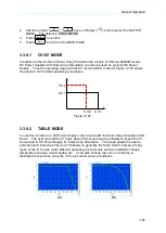
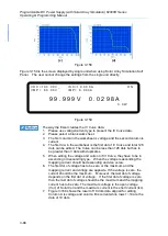
Page 129: ...detail operating procedures CV1 CV2 CC1 CC2 Figure 3 157 3 3 9 2 TABLE MODE To use this function in a DC Power Supply it has to work with the Solar Array Simulation Soft Panel The user can edit the IV Curve data in Excel and use the software to import the IV Curve data to DC Power Supply for Solar Array Simulation The mode allows the user to edit various IV Curves as Figure 3 158 shows to generate...

Page 130: ...ts can be edited The Curve can be less than 128 dots but has to be greater than 3 dots with duplicates 5 When editing the voltage and current of IV Curve they have to be in ascending or descending type When the voltage is ascending the mapping current should be descending and vice versa 6 The first dot of voltage has to be zero or the maximum and the mapping current and voltage are opposite If the...

Page 131: ...rence August 1993 ESA WPP 054 August 1993 for the built in model The model formula discussed in the thesis is described as below oc sc s sc s N sc oc V I R I I R I I V V 1 2 ln 2 ln where mp mp oc s I V V R sc mp a I I N ln 2 2 ln oc sc mp s oc sc s mp V I I R V I R V a 1 Voc Open Circuit Voltage Isc Short Circuit Current Vmp Max Power Voltage Imp Max Power Current Moreover due to the fact the mod...

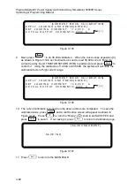
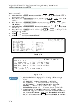
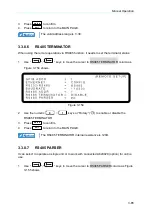
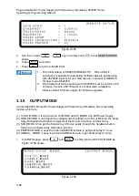
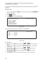
Page 132: ...gure 3 162 shows the screen when entered into the SAS MODE S A S M O D E V O C 1 0 0 0 0 V I S C 1 0 0 0 A V M P 6 0 0 0 V I M P 6 0 0 A _ Figure 3 162 Setting procedure 1 Move the cursor to VOC and use the numeric 0 9 keys to set the open voltage 2 Move the cursor to ISC and use the numeric 0 9 keys to set the short circuit current 3 Move the cursor to VMP and use the numeric 0 9 keys to set the ...

Page 133: ...rom the settings of user VMP and IMP via the hardware built in formula The user can change the VOC ISC VMP and IMP parameters directly using the function keys from the screen of single unit When any of the VOC ISC VMP or IMP is modified use to move the cursor to TRIG and press ENTER to confirm The IV curve will update immediately and so too the EQ_PMP EQ_VMP and EQ_IMP parameters 1 Definition of F...

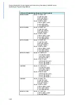
Page 134: ...Load 6 6ms 1000W 1 4ms 5000W 62150H 600S Delta V 600 to 0V 1s No Load 40ms 1500W 8ms 7500W Delta V 350 to 250V 160ms No Load 6 6ms 1500W 1 4ms 7500W 62150H 1000S Delta V 1000 to 0V 1 5s No Load 40ms 1500W 8ms 7500W Delta V 580 to 420V 240ms No Load 6 4ms 1500W 1 3ms 7500W A620028 Delta V 1000 to 0V 1 5s No Load 40ms 1500W 8ms 7500W Delta V 580 to 420V 240ms No Load 6 4ms 1500W 1 3ms 7500W A620027 ...

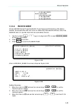
Page 135: ...curve simulation function 1 Use the numeric 0 keys or rotary knob to select EN50530_MODE as Figure 3 165 shows 2 Press ENTER to confirm 3 Press EXIT to return to the MAIN PAGE Figure 3 165 When in EN50530 _MODE the screen shows as Figure 3 166 Figure 3 166 Setting Procedure 1 Move the cursor to VMP and use the numeric keys 0 9 to set the maximum power voltage 2 Move the cursor to PMP and use the n...

Page 136: ...s that are calculated based on the settings set by the user of VMP and PMP via the hardware built in formula Use and to change the VMP and PMP parameters directly on the single unit screen When the parameter of VMP or PMP is change use to move the cursor to TRIG and press ENTER to confirm the change The IV curve will update immediately and so too the EQ_VOC EQ_VMP EQ_ISC and EQ_IMP parameters 3 3 ...

Page 137: ...and use the numeric keys 0 9 to set the fill factor 4 Move the cursor to BETA and use the numeric keys 0 9 to set the voltage temperature coefficient 5 Move the cursor to IRR and use the numeric keys 0 9 to set the irradiation 6 Move the cursor to IRR REF and use the numeric keys 0 9 to set the irradiation reference 7 Move the cursor to TMP and use the numeric keys 0 9 to set the temperature 8 Mov...

Page 138: ... the actual operating points that are calculated by the settings based on those set by the user of VMP and PMP via the hardware built in formula Use and to change the VMP and PMP parameters directly on the single unit screen When the parameter of VMP or PMP is change use to move the cursor to TRIG and press ENTER to confirm the change The IV curve will update immediately and so too the EQ_VOC EQ_V...

Page 139: ...7 Figure 3 173 When in EN50530 or SANDIA_MODE setting screen if the parameter shows negative after calculation the screen will show as Figure 3 174 Please press EXIT to return to OUTPUR_MODE for setting again Figure 3 174 ...

Page 140: ......

Page 141: ...voltage settings voltage slew rates current settings current slew rates run times and trigger types that can apply to almost any situation 1 Press PROG on the front panel 2 It displays PROGRAM options as Figure 4 1 shows 3 Use numeric keys 1 3 or Rotary knob to set the desired mode 4 Press ENTER to confirm 5 To quit PROGRAM just press EXIT to return to the MAIN PAGE P R O G R A M M O D E L I S T _...

Page 142: ...CE SEQ NO 2 SEQ TYPE AUTO TIME 0 000 S VOLTAGE 0 00V V S R 1 000 V ms CURRENT 0 000A I S R INF A ms SEQUENCE SEQ NO 3 SEQ TYPE AUTO TIME 0 000 S VOLTAGE 0 00V V S R 1 000 V ms CURRENT 0 000A I S R INF A ms SEQUENCE SEQ NO 4 SEQ TYPE AUTO TIME 0 000 S VOLTAGE 0 00V V S R 1 000 V ms CURRENT 0 000A I S R INF A ms EXT _TRIG PULL HIGH Figure 4 2 4 1 1 Description of PROGRAM Settings A PROGGRAM has 5 se...

Page 143: ...nalog Interface PIN 8 on the rear panel and change it to low level signal negative edge trigger to jump to the next sequence 4 1 1 2 Setting PROG NO 1 Use keys to move the cursor to the column to be set as Figure 4 3 2 shows 2 Use the numeric 0 9 keys or Rotary knob to set the value 3 Press ENTER to confirm 4 Press EXIT to return to Figure 4 1 P R O G R A M E X T _ T R I G P U L L H I G H _ P R O ...

Page 144: ...T is listed as Figure 4 4 shows A1 Execution steps 1 When all PROG 1 SEQUENCES are done return to PROG 1 2 Repeat step 1 twice and skip PROG 2 and return to PROG 3 3 When all PROG 3 SEQUENCES are done return to PROG 3 4 Repeat step 3 for 3 times 5 End PROG 1 PROG CHAIN NO 3 REMAIN COUNT 1 SEQ 1_1 SEQ 1_10 PROG 3 PROG CHAIN NO 0 REMAIN COUNT 2 SEQ 3_1 SEQ 3_10 START PROG 1 PROG CHAIN NO 3 REMAIN CO...

Page 145: ...O to 0 it means no program link 2 Set NEXT TO PROG NO to non 0 When setting NEXT TO PROG NO to non 0 it means to perform program link as the example listed below Ex Link execution among programs Set PROG 1 to NEXT TO PROG NO 3 RUN COUNT 1 PROG 3 to NEXT TO PROG NO 4 RUN COUNT 1 PROG 4 to NEXT TO PROG NO 6 RUN COUNT 1 PROG 6 to NEXT TO PROG NO 0 RUN COUNT 1 The program execution flow is listed as F...

Page 146: ... 5_1 SEQ 5_10 PROG 6 PROG CHAIN NO 0 SEQ 6_1 SEQ 6_10 PROG 7 PROG CHAIN NO 0 SEQ 7_1 SEQ 7_10 PROG 8 PROG CHAIN NO 0 SEQ 8_1 SEQ 8_10 PROG 9 PROG CHAIN NO 0 SEQ 9_1 SEQ 9_10 PROG 10 PROG CHAIN NO 0 SEQ 10_1 SEQ 10_10 END START Figure 4 5 Ex 3 Use a PROGRAM to form an infinite loop Set PROG 1 to NEXT TO PROG NO 1 RUN COUNT 1 The program execution flow is listed as Figure 4 6 shows A3 Execution step...

Page 147: ...O 6 RUN COUNT 1 PROG 6 to NEXT TO PROG NO 1 RUN COUNT 1 The program execution flow is listed as Figure 4 7shows A4 Execution steps 1 When all PROG 1 SEQUENCES are done skip PROG 2 and jump to PROG 3 2 When all PROG 3 SEQUENCES are done jump to PROG 4 3 When all PROG 4 SEQUENCES are done skip PROG 5 and jump to PROG 6 4 When all PROG 6 SEQUENCES are done skip PROG 7 PROG 10 and jump to PROG 1 5 Rer...

Page 148: ...PROG 7 PROG CHAIN NO 0 SEQ 7_1 SEQ 7_10 PROG 8 PROG CHAIN NO 0 SEQ 8_1 SEQ 8_10 PROG 9 PROG CHAIN NO 0 SEQ 9_1 SEQ 9_10 PROG 10 PROG CHAIN NO 0 SEQ 10_1 SEQ 10_10 START Figure 4 7 3 Press ENTER to confirm 4 Press EXIT to return to Figure 4 1 If it skips to next PROGRAM which has no SEQUENCE all SEQUENCES will set top SKIP see 4 1 2 2 SEQUENCE TYPE and the PROGRAM will stop execution 4 1 1 5 Settin...

Page 149: ... page will skip to Figure 4 8 b When the cursor is at 7 in Figure 4 8 as the SEQUENCE of a PROGRAM press can add a new SEQUENCE function key is usually used as cursor movement key only when in the above situations can it be used for adding new SEQUENCE 3 Use keys to move the cursor to the column to be set as Figure 4 8 shows 4 Use numeric keys 0 9 or Rotary knob to set the value S E Q U E N C E S ...

Page 150: ...re 4 3 4 1 2 2 Setting Sequence Type 1 Use keys to move the cursor to the column to be set as Figure 4 8 2 shows 2 Use numeric keys 0 3 or Rotary knob to set the Sequence Type There are four Sequence Types which are 1 AUTO 2 MANUAL 3 TRIGGER 4 SKIP a Setting Sequence Type to AUTO When SEQ TYPE AUTO is set the page shown as Figure 4 9 indicates the sequence will complete the execution automatically...

Page 151: ...COUNT 2 PROG CHAIN NO CLEAR PROG NO SEQUENCE SEQ NO 1 SEQ TYPE AUTO TIME 5 000 S VOLTAGE 10 00V V S R 1 000 V ms CURRENT 20 000A I S R 1 000 A ms SEQUENCE SEQ NO 2 SEQ TYPE AUTO TIME 10 000 S VOLTAGE 30 00V V S R 10 000 V ms CURRENT 20 000A I S R 1 000 A ms SEQUENCE SEQ NO 3 SEQ TYPE AUTO TIME 0 000 S VOLTAGE 0 00V V S R 1 000 V ms CURRENT 0 000A I S R 1 000 A ms SEQUENCE SEQ NO 10 SEQ TYPE AUTO T...

Page 152: ...rrent setting 20A therefore SEQ 2 is in CV Mode during voltage rise C Once the voltage reached the set 30V the program lasts for 10 seconds from rising D Skip to SEQ 3 3 SEQ 3 A Since SEQ TYPE AUTO and TIME 0 are set for SEQ 3 it indicates SEQ 3 is not executing and the Program is ended 4 As RUN COUNT 2 is set steps 1 2 and 3 are executed again 5 End Figure 4 11 shows the output waveform COUNT 1 C...

Page 153: ...criptions in section 4 1 1 1 for the definition of PIN 8 input signal for Analog interface It will not ask users to enter the time the sequence will remain when set to TRIGGER S E Q U E N C E S E Q N O 1 S E Q T Y P E T R I G G E R _ V O L T A G E 0 0 0 V V S R 1 0 0 0 V m s C U R R E N T 0 0 0 0 A I S R I N F A m s Figure 4 13 d Set Sequence Type to SKIP When SEQ TYPE SKIP is set the Sequence pag...

Page 154: ...ary knob to set the SEQ output voltage 3 Press ENTER to confirm 4 Press EXIT to return to Program PAGE Figure 4 3 See section 3 2 for detail description 4 1 2 5 Setting Voltage Slew Rate 1 Use keys to move the cursor to the column to be set as Figure 4 8 5 shows 2 Use numeric keys 0 9 or Rotary knob to set the SEQ voltage conversion slew rate 3 Press ENTER to confirm 4 Press EXIT to return to Prog...

Page 155: ...1 3 Execution in LIST MODE When the sequences are finished for editing press ON OFF to start execution and press EXIT to abort it 4 1 3 1 Running LIST MODE 1 Press ON OFF will prompt a confirmation page as Figure 4 15 shows Figure 4 15 2 Press ON OFF again to confirm the execution and go to the MAIN PAGE as Figure 4 16 shows To quit the execution press EXIT will return to the standby MAIN PAGE S E...

Page 156: ...1 2 3 4 5 Figure 4 17 1 Program Number PRG NO indicates the Program Number being executed at present 2 Sequence Number SEQ NO indicates the Sequence Number being executed at present 3 Sequence Status SEQ STATUS indicates the Sequence state being executed at present 4 Count_Remain COUNT_REMAIN indicates the numbers to be executed for the current Program 5 Running Time TIME indicates the sum of time...

Page 157: ...0 9 or Rotary knob to set the value 3 Press ENTER to confirm 4 Press EXIT to return to Figure 4 1 P R O G R A M S T E P S T A R T _ V O L T A G E 0 0 0 _ V E N D _ V O L T A G E 0 0 0 V R U N _ T I M E 0 0 0 0 0 1 2 3 Figure 4 19 CAUTION The initial voltage of the hardware does not equal to the setting of the START_VOLTAGE There are two circumstances that may occur in V_STEP MODE 1 The output volt...

Page 158: ... time format is HOUR MIN SEC and the maximum setting is 99 hours 59 minutes and 59 99 seconds 2 Use the numeric keys 0 9 or Rotary knob to set the value 3 Press ENTER to confirm 4 Press EXIT to return to Figure 4 1 When V_STEP MODE ends the hardware output voltage will remain at the setting of END_VOLTAGE Ex 1 Set the START_VOLTAGE to 10V END_VOLTAGE to 50V and RUN_TIME to 10 minutes CASE1 The har...

Page 159: ...t just press EXIT 4 2 2 1 Running V_STEP MODE 1 Press ON OFF will appear a confirmation window as Figure 4 15 shows 2 Press ON OFF one more time to confirm the execution It will skip to the MAIN PAGE during execution as Figure 4 23 shows To quit the execution press EXIT can return to the MAIN PAGE window at standby Press EXIT to interrupt the Program execution forcibly that is the Power Supply sto...

Page 160: ... T I M E 0 0 5 0 S T A R T _ V O L T 1 0 0 0 E N D _ V O L T 2 0 0 0 0 0 0 0 0 V 0 0 0 0 0 A 0 0 W 3 4 1 2 Figure 4 24 1 START_VOLT It is the start voltage setting of V_STEP MODE 2 END_VOLT It is the end voltage setting of V_STEP MODE 3 STEP STATUS It is the executing status of V_STEP MODE 4 ELAPSE TIME It is the executed time of V_STEP MODE The time format is HOUR MIN SEC and the maximum display ...

Page 161: ...V SEQUENCE SEQ NO 3 IV FILE NO 0 SEQ TYPE AUTO TIME 0 S Figure 4 25 4 3 1 Setting IV PROGRAM There are 4 items in IV PROGRAM including 1 PROG NO 2 RUN COUNT 3 PROG CHAIN and 4 CLEAR PROG as Figure 4 26 shows See section 4 1 1 2 to 4 1 1 5 for the detail of setting these 4 parameters I V P R O G R A M P R O G N O 1 _ R U N C O U N T 1 P R O G C H A I N N O C L E A R P R O G N O 1 2 3 4 Figure 4 26 ...

Page 162: ... 4 of Figure 4 27 press to add another new IV SEQUENCE The key is often used as the direction key and only used to add new IV SEQUENCE in the above two conditions 3 Use keys to move the cursor to the column to be set as Figure 4 27 shows I V S E Q U E N C E S E Q N O 1 _ I V F I L E N O 0 S E Q T Y P E A U T O T I M E 0 S 1 2 4 3 Figure 4 27 4 Use the numeric keys 0 9 or Rotary knob to set the val...

Page 163: ... 99 4 Press ENTER to confirm 5 Press EXIT to return to IV Program Page Figure 4 26 4 3 2 3 Setting Sequence Type 1 Use keys to move the cursor to the column to be set as Figure 4 27 3 shows 2 Use the numeric keys 0 1 or Rotary knob to set the Sequence Type There are two Sequence Types 1 AUTO and 2 MANUAL a Set the Sequence Type to AUTO When setting SEQ TYPE AUTO the IV Sequence page is as Figure 4...

Page 164: ...ntil the ENTER on the front panel is pressed The IV Sequence page will not ask the user to enter the sustained time when SEQ TYPE MANUAL I V S E Q U E N C E S E Q N O 1 I V F I L E N O 0 S E Q T Y P E M A N U A L _ Figure 4 29 3 Press ENTER to confirm 4 Press EXIT to return to IV Program Page Figure 4 26 4 3 2 4 Setting Time 1 Use keys to move the cursor to the column to be set as Figure 4 27 4 sh...

Page 165: ...N PAGE as Figure 4 31 shows To abort the execution press EXIT can return to the standby MAIN PAGE S E Q S T A T U S A U T O T I M E 0 0 0 0 0 20 P R O G 1 S E Q 1 F I L E 0 C N T _ R E M A I N 0 1 0 0 0 0 V 0 0 0 0 0 A V O C 1 0 0 0 0 V I S C 1 0 0 0 0 A 0 0 W V M P 9 0 0 0 V I M P 9 0 0 0 A Figure 4 31 1 Press ON OFF in IV Program page Figure 4 26 or IV Sequence page Figure 4 27 will prompt the c...

Page 166: ...ence on IV Main Page The time format is HOUR MIN SEC and the maximum time display is 99 hours 59 minutes and 59 seconds If the accumulated time exceeds the maximum time display it will reset to zero and re accumulate 3 IV Program Number PROG shows the IV Program Number executed at present 4 IV Sequence Number SEQ shows the IV Sequence Number executed at present 5 IV FILE Number FILE shows the IV F...

Page 167: ...e it is no need to install other drivers The OS will search for the standard USBTMC driver installation program automatically If the PC OS does not support USBTMC it is suggested to install the NI VISA runtime version 3 00 or above first When the installation of NI VISA runtime is done the USBTMC driver program is stored in OS The PC can communicate with 62000H Series via NI VISA after using the U...

Page 168: ...TR N C 5 GND DGND 6 DSR N C 7 RTS N C 8 CTS N C 9 N C N C N C stands for Not Connected 5 1 4 Connecting RS 485 The default transmission baudrate of 62000H Series is set to 115200 and the parity check is set to None The RS 485 interface is a half duplex two wire differential signaling transmission and only RS485_P and RS485_N signals are required for data transmission The connection is the same as ...

Page 169: ...ndividual device To set the IP address of Chroma 62000H Series just use the REMOTE setting in CONFIG menu This section describes how to use the network interface rapidly and correctly Be sure to read it clearly and carefully before using the 62000H network interface and ensure the network is connected firmly and correctly to the hardware before execution The transmission protocol of 62000HS Series...

Page 170: ...anual 5 4 5 1 5 1 Selecting the LAN to be Connected The LAN is divided into Site LAN and Private LAN Site LAN usually indicates the larger local area network such as Intranet that contains network server DHCP WINS DNS etc Terminator Router Firewall and Internet linkage as the figure shown below ...

Page 171: ... Source 62000H Site LAN Hub Private LAN indicates the smaller local area network that is composed of more than two terminators and Hub or two terminators linked through Crossover Cable For Model 62020H 150S both Crossover Cable and Non Crossover Cable can be used If Private LAN mode is selected the following two ways can be used to connect the PC 1 DC Source 62000H PC Crossover Cable ...

Page 172: ...eway 1 In Site LAN Only the 62000H needs to do network setting It can set DHCP to ON Server sets the IP automatically or OFF set IP manually For Model 62020H 150S please refer to 7 2 1 for network parameters setting Procedure for setting DHCP ON on Chroma DC Source STEP 1 Click CONFIG to enter into the CONFIG selections Find the DHCP location in the tree diagram listed below and set the DHCP to ON...

Page 173: ...S232 RS485 DHCP ON CONFIG PAGE IP ADDRESS XXX XXX XXX XXX GATEWAY ADDR XXX XXX XXX XXX SUBNET MASK XXX XXX XXX XXX APPLY YES BAUDRATE 8 REMOTE GPIB ADDR LAN Status STEP 2 Click downward to APPLY and set it to YES to confirm sending out the settings STEP 3 The screen will show the network setting status with one of the messages listed below ...

Page 174: ... setting the network parameter manually If the user knows the present network setting of PC the settings of SUBNET MASK and GATEWAY can be input to 62000H directly As to the IP Address it can set one with the same domain but different IP to 62000H For instance the PC s IP 10 1 7 100 Mask 255 255 254 0 Gateway 10 1 7 254 the user can set the IP 10 1 7 101 Mask 255 255 254 0 and Gateeway 10 1 7 254 ...

Page 175: ...H through Crossover Cable so these two devices have to set the IP manually For Model 62020H 150S please refer to section 7 2 1 for network parameters setting Procedure for setting DHCP OFF on PC Ensure the local area network setting is to set the IP manually If not change it to assign IP manually and complete the other settings STEP 1 Click Control Panel on the PC and click Network Connections STE...

Page 176: ...Programmable DC Power Supply with Solar Array Simulation 62000H Series Operating Programming Manual 5 10 STEP 3 Double click Internet Protocol TCP IP to enter into its setting screen ...

Page 177: ...nows the present network setting of PC the settings of SUBNET MASK and GATEWAY can be input to 62000H directly As to the IP Address it can set one with the same domain but different IP to 62000H For instance the PC s IP 10 1 7 100 Mask 255 255 254 0 Gateway 10 1 7 254 the user can set the IP 10 1 7 101 Mask 255 255 254 0 and Gateeway 10 1 7 254 for 62000H The premise is IP 10 1 7 101 is not being ...

Page 178: ...update and show the network settings automatically and clear the status message STEP 4 Save the settings and return to the panel main screen so that the 62000H will save the settings 5 1 5 3 Confirming Network Connected Successfully When the actions are done it means the environment of local area network is well setup including the Chroma DC Source 62000H network card Please follow the steps below...

Page 179: ...t The user can use the NI MAX Measurement Automation Explorer application software of National Instruments or customized program to communicate with the user s instrument If using NI VISA the user needs to open VISA Session Resource Name in the format of TCPIP0 IP address 2101 SOCKET such as TCPIP0 10 1 7 100 2101 SOCKET If not using NI VISA then specify the TCP IP SOCKET PORT to 2101 Following is...

Page 180: ...upply with Solar Array Simulation 62000H Series Operating Programming Manual 5 14 STEP 1 Open the NI MAX Ver 4 3 0F0 right click the Devices and Interface and click Create New STEP 2 Select VISA TCP IP Resource and click Next ...

Page 181: ...Remote Operation 5 15 STEP 3 Select Raw Socket and click Next STEP 4 Input the IP Address and Port Number the TCP IP Port used by 62000H is 2101 and click Validate ...

Page 182: ...mming Manual 5 16 STEP 5 The following screen will appear if the connection is successful Close this message and then click Finish to end it STEP 6 A VISA TCP IP Resource will be added to the Configuration list under Devices and Interfaces Click it to open the VISA Session NI VISA Ver 3 0 ...

Page 183: ...ttribute Name in Property Node Write under Template tab If the Current Value is set to VI_FALSE please change the New Value to VI_TRUE and click Execute STEP 8 Click Basic I O tab and use Write to write in the command to 62000H using IDN as the example and click Execute ...

Page 184: ...ad using a series poll Service Request It sets the SRQ line to true if there is an enabled service request condition Remote Local Power on in local mode the front panel can be operated and the commands are responded through GPIB When in remote mode all front panel keys are invalid except LOCAL Press LOCAL can return to local mode 5 3 Introduction to Programming All commands and response messages a...

Page 185: ...able 5 6 Table 5 6 Format of Numerical Data Symbol Description Example NR1 It is a digit without decimal point The decimal is assumed to be at the right of the least significant digit 123 0123 NR2 It is a digit with a decimal point 12 3 123 NR3 It is a digit with a decimal point and an exponent 1 23E 2 NRf Flexible decimal format including NR1or NR2 or NR3 123 12 3 23E 3 NRf Extended decimal forma...

Page 186: ...ontrolled headers 5 3 5 3 Common Command and Query Headers The syntax of common command and query headers is described in IEEE 488 2 It is used together with the IEEE 488 2 defined common commands and queries The commands with a leading are common commands 5 3 5 4 Instrument Controlled Headers Instrument controlled headers are used for all other instrument commands Each of them has a long form and...

Page 187: ...ith EOI The response message is terminated by NL END for GPIB and NL for other interfaces 5 4 Traversal of the Command Tree Multiple program message unit elements can be sent in a program message The first command is always referred to the root node Subsequent commands refer to the same tree level as the previous command in a program message A colon preceding a program message unit changes the hea...

Page 188: ...mmand sets the condition of the Standard Event Status Enable register which determines which events of the Standard Event Status Event register see ESR are allowed to set the ESB Event Summary Bit of the Status Byte register A 1 in the bit position enables the corresponding event All of enable events of the Standard Event Status Event register are logically ORed to cause the ESB bit 5 of the Statu...

Page 189: ...uery Syntax OPC Return Parameter NR1 Query Example 1 RCL Recall Instrument State Command Type Device status Description This command restores the High Slew Rate Load to a state that was previously stored in memory with the SAV command to the specified location see SAV Syntax RCL NR1 Parameter None Example RCL 1 RST Reset Command Type Device status Description Reset System Syntax RST Parameter None...

Page 190: ...atus bit instead of RQS bit is returned in Bit 6 This bit indicates if the High Slew Rate Load has at least one reason for requesting service STB does not clear the Status Byte register which is cleared only when subsequent action has cleared all its set bits Query Syntax STB Return Parameter NR1 Query Example STB Return the contents of Status Byte Return Example 20 1 Status Byte Register The Stat...

Page 191: ...et whenever there is data available in the output queue and is reset when the available data is read 3 0 Always 0 2 Standard Event Status Register The Standard Event Status Register is frequently used The common use commands ESE and ESR can be utilized to program it Operation Complete Queue Error Device Dependent Error Execution Error Command Error Power On Read Standard Event Status Register by E...

Page 192: ... 1 when reading data from the output buffer and no data is present or when the data is lost 1 Always 0 0 1 5 6 2 Specific Commands for 62000H Series 5 6 2 1 ABORT Subsystem ABORt Description It sets all output state to OFF Syntax ABORt 5 6 2 2 CONFIGURE Subsystem 1 CONFigure BEEPer Description It sets the beeper to ON or OFF Syntax CONFigure BEEPer ON CONFigure BEEPer OFF Parameter ON OFF Example ...

Page 193: ...BLE or CVTOCC or CCTOCV 5 CONFigure FOLDT Description It sets the delay time of FOLDBACK PROTECT Syntax CONFigure FOLDT NRf Parameter 0 01 600 00 Unit Sec Example CONF FOLDT 10 Query Syntax CONF FOLDT Return Parameter NRf1 Query Example CONF FOLDT Return Example 1 000000e 01 6 CONFigure APGVSet Description It sets the action type of APG VSET Syntax CONFigure APGVSet NONE CONFigure APGVSet VREF5 CO...

Page 194: ...mple CONFigure APGIMeas Return Example VREF10 10 CONFigure AVG TIMES Description It sets the average times of measurement for input voltage current Syntax CONFigure AVG TIMES NR1 Parameter NR1 0 1 time 1 2 times 2 4 times 3 8 times Example CONFigure AVG TIMES 0 CONFigure AVG TIMES 1 Query Syntax CONFigure AVG TIMES Return Parameter 1 2 4 8 Query Example CONFigure AVG TIMES Return Example 1 11 CONF...

Page 195: ... 14 CONFigure MSTSLV PARSER Description It sets to series or parallel mode Syntax CONFigure MSTSLV PARSER PARALLEL CONFigure MSTSLV PARSER SERIES Parameter PARALLEL SERIES Example CONFigure MSTSLV PARSER PARALLEL CONFigure MSTSLV PARSER SERIES Query Syntax CONFigure MSTSLV PARSER Return Parameter PARALLEL SERIES Query Example CONF MSTSLV PARSER Return Example PARALLEL Note CONFigure MSTSLV must be...

Page 196: ...ion It enables the Remote Inhibit control Syntax CONFigure INHibit ARG Parameter DISABLE ENABLE Example CONFigure INHibit DISABLE CONFigure INHibit ENABLE Query Syntax CONFigure INHibit Return Parameter DISABLE ENABLE Query Example CONF INH Return Example DISABLE 18 CONFigure INHibit PULL Description It controls the internal resistance status of Remote Inhibit input signal Syntax CONFigure INHibit...

Page 197: ... Description It enables the External ON OFF control Syntax CONFigure EXTON ARG Parameter DISABLE ENABLE Example CONFigure EXTON DISABLE CONFigure EXTON ENABLE Query Syntax CONFigure EXTON Return Parameter DISABLE ENABLE Query Example CONF EXTON Return Example DISABLE 22 CONFigure EXTON PULL Description It controls the internal resistance status of External ON OFF input signal Syntax CONFigure EXTO...

Page 198: ... SOUR VOLT LIMIT LOW Return Parameter NRf Unit Volt Query Example SOUR VOLT LIMIT HIGH It returns the maximum range set for voltage Return Example 8 000000e 01 3 SOURce VOLTage PROTect HIGH Description It sets the voltage range for over voltage protection Syntax SOURce VOLTage PROTect HIGH NRf Parameter Refer to individual spec for valid numeric range Example SOUR VOLT PROT HIGH 60 0 It sets the h...

Page 199: ...p Query Example SOUR CURR LIMIT HIGH It returns the maximum range set for current Return Example 6 000000e 01 7 SOURce CURRent PROTect HIGH Description It sets the current range for over current protection Syntax SOURce CURRent PROTect HIGH NRf Parameter Refer to individual spec for valid numeric range Example SOUR CURR PROT HIGH 60 0 It sets the high limit to 60A for current output protection Que...

Page 200: ... Syntax SOURce POWer PROTect HIGH NRf Parameter Refer to individual spec for valid numeric range Example SOURce POWer PROTect HIGH 1260 It sets the over power point 1260 Query Syntax SOURce POWer PROTect HIGH Return Parameter NR f Watt Query Example SOURce POWer PROTect HIGH It returns the over power setting value Return Example 1 260000e 03 11 SOURce DCON RISE FALL Description It sets the DC_ON s...

Page 201: ...ower Supply and returns real time power Query Syntax FETCh POWer Return Parameter NRf Unit Amp Query Example FETC POW Return Example 5 000000e 03 4 FETCh STATus Description It returns the status code of Power Supply s state Query Syntax FETCh STATus Return Parameter Arg1 Arg2 Arg3 Arg1 return warning message 0 65535 0 no warning use binary for the rest and identify the cause of error BIT 0 OVP BIT...

Page 202: ...r NRf Unit Voltage Query Example MEAS VOLT Return Example 8 120000e 01 2 MEASure CURRent Description It returns the current measured at the output of Power Supply Query Syntax MEASure CURRent Return Parameter NRf Unit Amp Query Example MEAS CURR Return Example 3 150000e 01 3 MEASure POWer Description It returns the power measured at the output of Power Supply Query Syntax MEASure POWer Return Para...

Page 203: ... PROG LINK Return Example 7 3 PROGram COUNT Description It sets the program file to be executed in series Syntax PROGram COUNT NR1 Parameter 1 to 15000 Example PROG COUNT 7 Query Syntax PROG COUNT Return Parameter NR1 Query Example PROG COUNT Return Example 7 4 PROGram RUN Description It executes the program Syntax PROGram RUN ON PROGram RUN OFF Parameter ON 1 OFF 0 Example PROG RUN ON Query Synta...

Page 204: ...Quence TYPE MANUAL Parameter SKIP AUTO MANUAL Example PROG SEQ TYPE TRI PROG SEQ TYPE AUTO PROG SEQ TYPE MANUAL Query Syntax PROG SEQ TYPE Return Parameter SKIP AUTO MANUAL Query Example PROG SEQ TYPE Return Example 1 9 PROGram SEQuence VOLTage Description It sets the sequence for voltage output Syntax PROGram SEQuence VOLTage NRf Example PROG SEQ VOLT 40 5 Query Syntax PROG SEQ VOLT Return Parame...

Page 205: ...o INF PROGram SEQuence CURRent SLEWINF DISABLE releases the Slewrate INF and return to 1A ms Query Syntax PROGram SEQuence CURRent SLEW Return Parameter INF Or NRf Unit Amp Query Example PROGram SEQuence CURRent SLEW It returns the settings Return Example INF 14 PROGram SEQuence TIME Description It sets the sequence for the duration of time Syntax PROGram SEQuence TIME NRf Parameter 0 005 15000 0 ...

Page 206: ... valid when Sequence Type is AUTO Example Set the Sequence PROGram SEQuence 0 80 10 15 1 0 10 Query Syntax PROG SEQ Return Parameter 0 8 000000e 01 1 000000e 01 1 500000e 01 1 000000e 00 0 1 000000e 01 Query Example PROG SEQ Return Example 0 8 000000e 01 1 000000e 01 1 500000e 01 1 000000e 00 0 1 000000e 010 80 10 15 1 0 1 19 PROGram MODE Description It sets the Program Mode for output Syntax PROG...

Page 207: ...ery Example PROGram STEP ENDV Return Example 5 000000e 01 22 PROGram STEP TIME Description It sets the execution time for Step Mode Syntax PROGram STEP TIME Hour Minute Second Parameter Hour NR1 0 99 Minute NR1 0 59 Second NR f 0 59 99 Example It changes the time for STEP Mode action to 1 hour 30 min 5 sec PROGram STEP TIME 1 30 5 Query Syntax PROGram STEP TIME Return Parameter Hour Minute Second ...

Page 208: ...IMPp Description It queries the IMPp in IV Curve Mode Query Syntax IVCurve IMPp Return Parameter NRf Query Example IVCurve IMPp Return Example 5 000000e 00 5 IVCurve PMPp Description It queries the PMPp in IV Curve Mode Query Syntax IVCurve PMPp Return Parameter NRf Query Example IVCurve PMPp Return Example 5 000000e 01 6 IVCurve VT Description It sets the stored 128 dots voltage data in IV Curve ...

Page 209: ...rve EDIT NR1 Example It sets the IV Curve stored table to 1 IVCurve EDIT 1 Query Syntax IVCurve EDIT Return Parameter NR1 Query Example IVCurve EDIT Return Example 1 9 IVCurve SELect NR1 Description It selects the stored table to be run in IV Curve Mode There are 100 storted tables 1 100 and the default is 1 Syntax IVCurve SELect NR1 Example It selets the IV Curve stored table to 1 IVCurve SELect ...

Page 210: ... to add a new Sequence 12 IVCurve SEQuence RUN Description It queries the running status of IV Program Query Syntax IVCurve SEQuence RUN Return Parameter ARG1 ARG2 ARG7 ARG1 It is running status at present 0 STOP 1 RUNNING ARG2 It is Program No running at present ARG3 It is the remaining count of the Program run at present ARG4 It is Sequence No running at present ARG5 It is the Sequence Type 0 AU...

Page 211: ...Description It sets the IV Curve output response speed Syntax IVCurve CONFigure SPEed Parameter SLOW MIDDLE FAST Query Syntax IVCurve CONFigure SPEed Return Parameter SLOW MIDDLE FAST Example IVC CONF SPE FAST It sets the IV Curve output response speed to FAST Query Example IVC CONF SPE FAST Return Example SLOW MIDDLE FAST 16 IVCurve CONFigure MARGIN Description It sets the IV Curve margin unit Sy...

Page 212: ...SAS ISC Return Example 8 000000e 00 3 SAS VMPp Description It sets the VMPp in SAS Mode Syntax SAS VMPp NRf Example It changes the VMPp of SAS to 500 0 V SAS VMPp 500 Query Syntax SAS VMPp Return Parameter NRf Query Example SAS VMPp Return Example 5 000000e 02 4 SAS IMPp Description It sets the IMPp in SAS Mode Syntax SAS IMPp NRf Example It changes the IMPp of SAS to 5 0 A SAS IMPp 5 Query Syntax...

Page 213: ...turn Parameter NRf Query Example SAS VMPp Return Example 5 000000e 02 8 SAS TECH Description It sets the TECH in EN50530 Mode Syntax SAS TECH NR1 Parameter CSI TF Example SAS TECH CSI SAS TECH TF Query Syntax SAS TECH Return Parameter CSI TF Query Example SAS TECH Return Example CSI 9 SAS IRR Description It sets the irritation in EN50530 Mode Syntax SAS IRR NR1 Parameter NR1 Example SAS IRR 1000 S...

Page 214: ...ter NRf Example SAS SANDIA BETA 0 SAS SANDIA BETA 2 Query Syntax SAS SANDIA BETA Return Parameter NRf Query Example SAS SANDIA BETA Return Example 2 000000e 00 13 SAS SANDIA FF Description It sets the fill factor in SANDIA Mode Syntax SAS SANDIA FF NRf Parameter NRf Example SAS SANDIA FF 0 4 SAS SANDIA FF 0 95 Query Syntax SAS SANDIA FF Return Parameter NRf Query Example SAS SANDIA FF Return Examp...

Page 215: ...NDIA to 500 0 V SAS SANDIA VMPp 500 Query Syntax SAS SANDIA VMPp Return Parameter NRf Query Example SAS SANDIA VMPp Return Example 5 000000e 02 5 6 2 9 OUTPUT Subsystem 1 OUTPut STATus Description It enables or disables the DC Power Supply output To stop the output is to set the output voltage to 0 volt Query Syntax OUTPut STATus Parameter OFF ON Return Parameter OFF ON 2 OUTPut MODE Description I...

Page 216: ...Programmable DC Power Supply with Solar Array Simulation 62000H Series Operating Programming Manual 5 50 IVCurve SELect NR1 OUTPut ON ...

Page 217: ...allowed 106 Illegal parameter value 108 Parameter not allowed 109 Missing parameter 112 Program mnemonic too long 113 Undefined header 121 Invalid character in number 123 Numeric overflow 124 Too many digits 131 Invalid suffix 141 Invalid character data 148 Character data not allowed 151 Invalid string data 158 String data not allowed 202 Setting conflict 203 Data out of range 204 Too much data 21...

Page 218: ......

Page 219: ...ard has 24 4 6 keys and an LED L board is the low voltage input rectifier NO board is the output noise board O board is the output stage secondary side R board is the adapter of Remote sense and current sharing S board is the output stage secondary side snubber circuits U board provides serial parallel communication for System Bus and external RS232 RS485 and USB interfaces Y board is the converte...

Page 220: ...n_Fault1 SCR Control Signal J1 J2 J3 GND2 Fan Power Ground 12V3 Digital Board Power 220V INPUT Capacitor in Parallel 380 440V INPUT Capacitor in Series EMI Filter Auxiliary Power 5VD 16VD 12VO 12VO 48V I P STAGE Figure 6 2 Figure 6 3 shows the output stage structure Dummy Load vo vo svo svo O P Stage Isolated Driver 12VO OGND CV CC Dectect ADC Converter DAC Converter PWM Current Feedback V_DCBUS G...

Page 221: ...C_Fault signal C Board F Board Driver signal SCR driver signal 1 2VD D Board Figure 6 4 6 2 Function Description 6 2 1 I P PFC Stage 1 The input stage is a bridge rectifier to rectify the 3 phase power source to DC 2 The way input stage inhibits inrush current is to connect the input circuit to a 40 resistor in series during power on to charge the input capacitor Turn on the SCR after a few second...

Page 222: ...ing controls the IC detecting signal 1 Output voltage 2 The load actual voltage remote sense through output line In Constant Current mode following controls the IC detecting signal 1 Output current 3 The secondary side is one stage LC filter to lower down the ripple voltage and ripple current 4 The action of Dummy load is Constant Current Source and the Dummy load current will adjust following the...

Page 223: ...0S Only 7 1 Usage of Web Page 7 1 1 Home Page index html 1 LOGO display area 2 Function page switch area for switching Configuration Soft Panel and SCPI 3 pages 3 Functions setting area that can set the associate function buttons and messages based the page selected 2 1 3 ...

Page 224: ...nd DNS Server s are defined by TCP IP Configuration Mode for editing It is editable if set to Manual and unable to edit when set to Automatic 2 Refresh button This function refreshes the configuration page by reading the associate info again to display on the message block 1 3 LAN Configuration Initialize button It initializes the network to return to the factory default without using the settings...

Page 225: ... initialization is done the system password will be set to blank 4 Update function password required The execution process of this function is similar to LAN Configuration Initialize The difference is that the Update will use the Message block 1 settings to reset the network configuration 5 Password change block It is used to change the password by entering the following Password New Password Conf...

Page 226: ...ers 1 Voltage It sets the device voltage 2 Current It sets the device current 3 Output Mode It enables or disables the device output Every time when entering the Soft Panel page the item 1 2 will automatically read the device settings at present Reading Value 4 Voltage It reads the device output voltage 5 Current It reads the device output current 6 Power It reads the device output power 7 CV CC I...

Page 227: ... strings to the device to activate the function 3 Result The return message display area If the command sent to the device has a return value it will display here 7 1 5 Remarks 1 If the system password is blank there is no need to enter the password 2 Once the entered password is confirmed the rest of the functions that are protected by the password will not ask for password confirmation again unl...

Page 228: ...a few seconds to enter into the MAIN PAGE V 0 0 0_ V I 0 0 0 A O F F 0 0 0 0 0 V 0 0 0 0 0 A 0 0 W In the MAIN PAGE press CONFIG to enter into the CONFIG page Select SYSTEM SETUP in the CONFIG page and press ENTER In the SYSTEM SETUP page select ETHERNET CONFIG and press ENTER to go to ETHERNET CONFIG 1 2 page Note The ETHERNET configuration and network identification functions are set and display...

Page 229: ...ess to return to ETHERNET CONFIG 1 2 page 7 3 LAN Configuration Initialize LCI Function Continue to press in ETHERNET CONFIG 1 2 page until it reaches LCI turn the rotary knob to YES and press ENTER The RUN LCI page will appear Turn the rotary knob to YES and press ENTER to execute the LCI function It will show LAN Status SETTING when the network is initializing Once the settings are done the disp...

Page 230: ...network settings will be ignored When the modification is done go to APPLY and turn the rotary knob to YES and press ENTER to update the network configuration During update It will show LAN Status SETTING and then return to LAN Status READY when the update is done 7 3 2 Status Indicator RENEWAL FAIL will show on the lower right corner when DHCP Lease Renewal fails DUPLICATE IP will show on the low...

Page 231: ...ngs Over Current Protection OCP The output current exceeds the spec or OCP settings Remove the over load or enlarge the OCP settings Fan Fail Protection FAN LOCK 1 The fan is out of order 2 The feedback circuit is abnormal Consult with your local sales agent if it is unable to reset the protection state Input Error Protection 1 AC AFULT The voltage of AC input line is either too low or too high Ad...

Page 232: ...ssistance D D power stage error protection D D FAULT 1 The transient current is too big 2 The D D power stage is damaged 1 When D D FAULT protection occurs first turn off the power supply and remove the load Also make sure cables are connected correctly and then power it on again 2 Consult with your local sales agent for further assistance MATCH warning as the models are incompatible when connecti...

Page 233: ...V voltage programming for APG only that allows users to set in voltage form see section 3 3 1 1 for detail description 5 PIN 5 AVO_MEAS_C voltage programming for APG only that allows users to set in current form see section 3 3 1 1 for detail description 6 PIN 6 AVO_MEAS_V voltage programming for APG only that allows users to set in voltage form see 3 3 1 1 for detail description 7 PIN 7 N C 8 PIN...

Page 234: ... detail description 18 PIN 18 AIO_MEAS_C current programming for APG only that allows users to set in current form see section 3 3 1 1 for detail description 19 PIN 19 AIO_MEAS_V current programming for APG only that allows users to set in voltage form see 3 3 1 1 for detail description 20 PIN 20 N C 21 PIN 21 INTERLOCK this function allows users to use the Pin 21 of ANALOG INTERFACE to control th...

Page 235: ...rature protect OTP CC TO CV mode change protect CC TO CV FOLDBACK Fan fail protect FANLOCK Current sharing protect CURR SHARING ERR Current sharing cable connection error C S CABLE ERR D D power stage error protect D D FAULT FPGA UPDATE version incompatible protect FPGA IS TOO OLD PLS UPDATE MATCH warning as the models are incompatible when connecting in series or parallel ERROR MASTER OR SLAVE NO...

Page 236: ...oyuan 33383 Taiwan 台灣桃園市 33383 龜山區 華亞一路 66 號 T 886 3 327 9999 F 886 3 327 8898 Mail info chromaate com http www chromaate com Copyright by CHROMA ATE INC All Rights Reserved All other trade names referenced are the properties of their respective companies ...

Reviews: