21
English
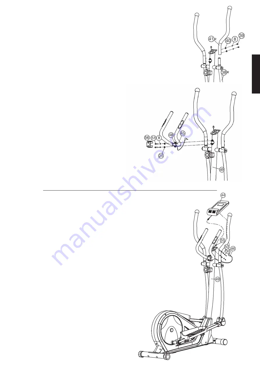
Step 5:
Installation of handgrips (41) at connecting tubes (38).
1. Push the handgrip bars (41L+41R) onto the connecting tubes (38) and
adjust the holes in the tubes so that they are aligned.
(
Note:
the handgrip bars must be aligned after assembly so that the
upper ends are inclined outwards (away from the support (49)).
2. Push the bolt M8x16 (39) with curved washers 8//20 (40) and spring
washer for M8 (8) through the holes and tighten the handgrip bars (41)
firmly.
Step 6:
Attach the handle grip (48) at support (49).
1. Push a washer 8//16 (25) and a spring washer for M8 (8) onto each screw
M8x25 (51). Place the handle grip (48) against the holder at support (49)
and tighten the handle grip (48) at handlebar support (49) firmly.
2. Cover the connectionpoint of handlegrip (48) with handlebarcover (56).
Step 7:
Attach the computer (44) at support (49).
1. Take the computer (44) that has been supplied out of the packaging and
insert the batteries (Type “AAA”-1.5 V pencells) by watching for the right
polarity on the back of the computer (44). (Batteries for the computer are
not included in this item. Please buy them at your located market.)
2. Put the plug of connection cable (55) into the plug from computer (44)
backside.
3. Insert the plug of pulse cable (46) to the jack of the computer (44) and
attach the computer (44) to top monitor bracket of front post (49) with
screws M5x10 (50) and washers 5//10 (30). (Attention: Ensure that the
cables are not crunched or pinched during installation.)
Step 8:
Checks
1. Check the correct installation and function of all screwed and plug con-
nections. Installation is thereby complete.
2. When everything is in order, familiarize yourself with the machine at a
low resistance setting and make your individual adjustments.
Note:
Please keep the tool set and the instructions in a safe place as these may
be required for repairs or spare parts orders becoming necessary later.


