background image

25

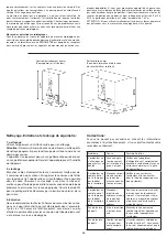
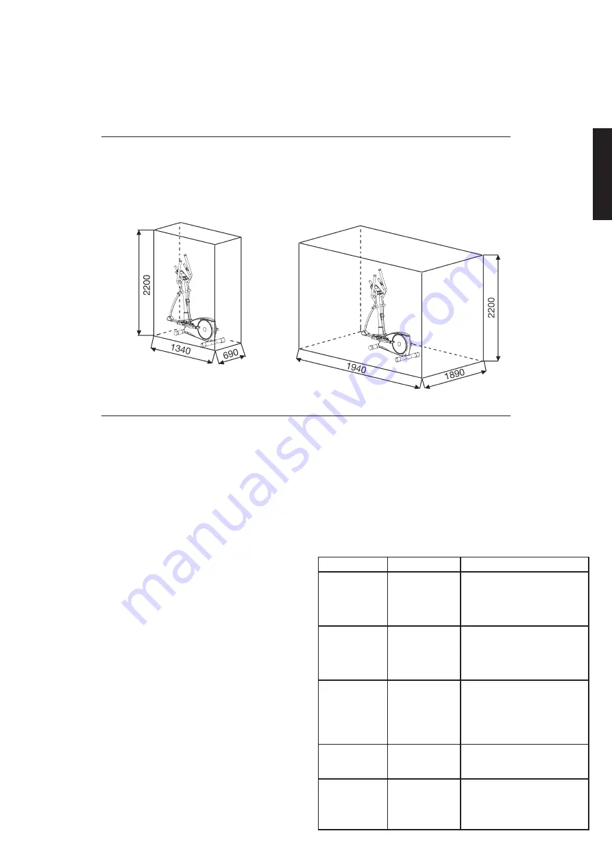
Training area  in mm
(for home trainer and user)

Free area in mm
(Training area and security area 
(rotating 60cm))

“WARNING” Heart rate monitoring system may be inaccurate. Over exercise 
may result in injury or death. If you feel faint stop exercising immediately.

Cardio Pulse Rate:

A pulse belt receiver is already included the computer. Belts that are un-
coded and work with frequency of 5.0-5,5kHz can communicate with the 
pulse measurement of computer. The distance of belt concerning computer 
should not overtake 1-1.5m. Note, if you use both systems the hand pulse 
measurement has priority.

Cleaning,  Checks  and  Storage  of  the  Ergometer 
bike: 

1. Cleaning

Use only a less wet cloth for cleaning. 

Caution:

 Never use benzene, 

thinner or other aggressive cleaning agents for surface cleaning as 
this damage caused.
The device is only for private home use and for use suitable indoors.
Keep the unit clean and moisture from the device.

2. Storage

Plug out the power supply unit while intending the unit for more than
4 weeks not to use. Choose a dry storage in-house and put some 
spray oil at front & rear foot tube connection point and hand grip 
axle. Cover the bike to protect it from being discolor by any sunlight 
and dirty through dust.

3. Checks

We recommend every 50 hours to review the screw connections for
tightness, which were prepared in the assembly. Every 100 operating
hours, you should put some spray oil at front & rear foot tube con-
nection point and hand grip axle.

Troubleshooting

If  you  cannot  solve  the  problem  with  the  following  information, 
please contact the authorized service center.

Problem

Possible Cause

Solution

Computer has 
no value at Dis-
play if you press 
any key.

No power 
adapter is well 
plugged or wall 
power is without 
power. 

Check that the power adapter 
is properly plugged in, possibly 
with another electric device 
check if the wall power is fine.

Computer is 
not counting 
data and do not 
switch on after 
start cycling.

Sensor impulse 
missing base on 
not well plugged 
connection

Check the plug connections at 
computer and inside of handle-
bar support.  

Computer is 
not counting 
data and do not 
switch on after 
start cycling.

Sensor impulse 
missing base on 
not correct posi-
tion of sensor.

Take off the cover and check 
the distance between magnet 
and Sensor. The magnet at 
turning belt wheel should have 
only less than < 5mm distance 
against the sensor position.

No pulse value

Pulse cable is 
not plugged in.

Check the separately pulse 
cable is well connected with 
computer.

No pulse value

Pulse sensors 
not well connec-
ted

Screw out the screw for pulse 
measurement and check if 
plugs are well connected and no 
damage at pulse cable.

English

Summary of Contents for 1827

Page 1: ...Bedienungsanleitung für Bestell Nr 1827 Notice de montage et d utilisation du No de commande 1827 Assembly and exercise instructions for Order No 1827 Montage en bedieningshandleiding voor Bestellnummer 1827 GB D F NL RU Инструкция по монтажу и эксплуатации заказа 1827 ...

Page 2: ... im Beisein einer weiteren Person benutzen die Hilfestellung und Anlei tung geben kann Kindern ist es untersagt das Sportgerät zu benutzen und eine Benutzung des Sportgerätes durch unbeaufsichtigte Kinder ist durch geeigneteMaßnahmen auszuschließen 15 Es ist darauf zu achten dass der Trainierende und andere Personen sich niemals mit irgendwelchen Körperteilen in den Bereich von sich noch bewegende...

Page 3: ...3 Montageübersicht Assembly overview Aperçu de l Assemblée Montage overzicht Обзор Ассамблея D GB F NL RU ...

Page 4: ...4 ...

Page 5: ...terabdeckung 1 4 8 36 1827 06 BT 7 Schraube 4x20 2 4 6 39 9909 SW 8 Stützrohr 1 40 33 1827 02 SI 9 Kunststofflager 2 8 36 1502 41 BT 10 Wellscheibe 17 25 2 11 36 9918 22 BT 11 Griffachse 1 8 33 1827 13 SI 12 Kugellager 6203 8 13 19 34 36 9805 31 BT 13 Handgriff links 1 34 33 1827 03 SW 14 Unterlegscheibe 8 22 4 15 99 39 10159 15 Schraube M8x16 2 11 39 9823 16 Schraubenkappe 2 13 19 36 1827 27 BT 1...

Page 6: ...skabel 1 58 36 1206 32 BT 59 Mutter M6 1 24 39 9861 VZ 60 Sensorkabel 1 40 36 1827 19 BT 61 Tretkurbelscheibe 1 64 36 1827 20 BT 62 Selbstsichernde Mutter M6 5 63 39 9816 VC 63 Schraube M6x16 4 61 64 39 10120 SW 64 Tretkurbelachse 1 51 61 33 1827 15 SI 65 Flachriemen 490 J6 1 61 70 36 1827 21 BT 66 Achsmutter 3 8 2 68 39 9820 SW 67 Achsmutter schmal 3 8 3 48 39 9820 68 Schwungradachse 1 70 33 1827...

Page 7: ...27 30 BT 102 Sicherungsring C40 2 100 103 36 1827 18 BT 103 Fußhebel links 1 34 91 33 1827 12 SW 104 Fußschale 2 100 103 36 1827 09 BT 105 Unterlegplatte 4 104 36 9124 18 BT 106 Schlossschraube M6x50 4 104 39 10410 SW 107 Sterngriffmutter M6 4 106 36 9824 10 BT 108 Unterlegscheibe 6 13 5 76 106 39 10013 VC 109 Federring für M6 4 106 39 9865 SW 110 Fußhebelabdeckung links 2 100 103 112 36 1827 10 B...

Page 8: ...ne Unterlegscheiben 8 19 33 und Federringe für M8 27 griffbereit neben den vorderen Teil des Grundrahmens 40 legen 2 Das untere Ende des Stützrohres 8 zum Grundrahmen 40 führen und die Enden der beiden Computerkabelstränge 2 39 die aus 8 40 ragen zusammenstecken Achtung Das oben aus dem Stützrohr 8 ragende Ende des Verbindungskabels 2 darf nicht in das Rohr rutschen da es zur weiteren Montage noch...

Page 9: ...ie Pulskabel 25 in die Steckbuchsen 30 vorne am Stützrohr 8 einstecken Deutsch Schritt 5 Montage der Fußschalen 104 auf den Fußhebeln 100 103 1 Die Fußschale 104 auf den linken Fußhebel 103 auflegen und die Bohrungen in den Teilen so ausrichten dass sie übereinander liegen Achtung Die hohen Ränder der Fußschalen 104 müssen jeweils nach innen zum Grundrahmen hin ausgerichtet sein Ebenso eingestellt...

Page 10: ...21 zur Aufnahme am Stützrohr 8 führen und so ausrichten dass das Lochbild des Griffes 21 und des Stützrohres 8 übereinstim men Auf die Schrauben M8x25 26 jeweils einen Federring für M8 27 und eine Unterlegscheibe 8 16 28 aufstecken und damit den Griff 21 am Stützrohr 8 festschrauben Schritt 9 Kontrolle 1 Alle Verschraubungen und Steckverbindungen auf ordnungsgemäße Montage und Funktion prüfen Die ...

Page 11: ...ängiges Training ohne äußere Einflüsse sowie bei evtl Gruppenzwang das Risiko von Überanstrengungen oder Stürzen Die Kombination aus Radfahren Steppen und Laufen bietet ein Herz Kreislauf Training ohne Überforderung aufgrund der Möglichkeit des selbst einstellbaren Widerstandes Somit ist ein mehr oder weniger Intensives Training möglich Es trainiert die unteren und oberen Extremitäten stärkt das H...

Page 12: ...fung Einstellung des Gerätes Bitte berücksichtigen Sie dass eine Abweichungstoleranz wie auf Seite 2 angemerkt zulässig ist Stufe U min 30 UPM WATT 40 UPM WATT 50 UPM WATT 60 UPM WATT 70 UPM WATT 1 7 12 18 25 33 2 10 16 25 35 46 3 13 21 32 45 59 4 15 26 39 55 72 5 18 31 46 65 86 6 21 36 53 75 99 7 24 41 60 85 113 8 26 45 67 95 125 9 29 50 74 105 137 10 32 54 81 115 150 11 35 59 89 125 163 12 38 64...

Page 13: ...ste beendet oder unterbricht das Programm 1 Manual Manuelles Programm Einstellung des Widerstandlevels mittels de Tasten anhand der Stufen anzeige auf dem Display dann wenn nötig Einstellung der Trainingspara meter ZEIT ENTFERNUNG KALORIEN PULS Mit der Taste START STOP beginnen Sie das manuelle Programm 2 Program Trainingsprogramme 12 verschiedene Trainingsprogramme P1 P12 für abwechslungsreiches ...

Page 14: ...Ihren Händler oder den Hersteller Problem Mögliche Ursache Lösung Der Computer schaltet sich durch Drücken einer Taste nicht ein Kein Netzteil ein gesteckt oder die Steckdose führt keine Spannung Überprüfen Sie ob das Netzge rät ordnungsgemäß eingesteckt wurde ggf mit einem anderen Verbraucher ob die Steckdose Spannung führt Der Computer zählt nicht und schaltet sich durch Beginn des Trainings nic...

Page 15: ... Körpertemperatur und die Sauerstoffzufuhr langsam gesteigert werden Dieses ist durch gymnastische Übungen über eine Dauer von fünf bis zehn Minuten möglich Danach sollte das eigentliche Training Trainings Phase beginnen Die Trainingsbelastung sollte erst einige Minuten gering sein und dann für eine Periode von 15 bis 30 Minuten so gesteigert werden daß sich der Puls im Bereich zwischen 70 und 85 ...

Page 16: ...ds and handicapped persons should only use the machine in the presence of another person who can give aid and advice Children are forbidden to use the equipment 15 Ensure that the person conducting training and other people never move or hold any parts of their body into the vicinity of moving parts 16 At the end of its life span this product is not allowed to dispose over the normal household was...

Page 17: ...w 4x20 2 4 6 39 9909 SW 8 Handle tube 1 40 33 1827 02 SI 9 Plastic bushing 2 8 36 1502 41 BT 10 Wave washer 17 25 2 11 36 9918 22 BT 11 Center axis 1 8 33 1827 13 SI 12 Bearing 6203 8 13 19 34 36 9805 31 BT 13 Hand grip left 1 34 33 1827 03 SW 14 Washer 8 22 4 15 99 39 10159 15 Screw M8x16 2 11 39 9823 16 Screw cover 2 13 19 36 1827 27 BT 17 Foam 2 13 19 36 1827 13 BT 18 End cap 2 13 19 36 1827 14...

Page 18: ...cket 1 58 36 1206 32 BT 59 Nut M6 1 24 39 9861 VZ 60 Sensor wire 1 40 36 1827 19 BT 61 Belt pulley 1 64 36 1827 20 BT 62 Nylon nut M6 5 63 39 9816 VC 63 Screw M6x16 4 61 64 39 10120 SW 64 Pedal axle 1 51 61 33 1827 15 SI 65 Belt 490 J6 1 61 70 36 1827 21 BT 66 Axle nut 3 8 2 68 39 9820 SW 67 Axle nut small 3 8 3 48 39 9820 68 Flywheel axis 1 70 33 1827 16 SI 69 Bearing 6300 1 70 36 9211 36 BT 70 F...

Page 19: ...2 100 103 36 1827 30 BT 102 C clip C40 2 100 103 36 1827 18 BT 103 Pedal tube left 1 34 91 33 1827 12 SW 104 Pedal 2 100 103 36 1827 09 BT 105 Washer for pedal 4 104 36 9124 18 BT 106 Carriage screw M6x50 4 104 39 10410 SW 107 Pedal knob M6 4 106 36 9824 10 BT 108 Washer 6 13 5 76 106 39 10013 VC 109 Spring washers for M6 4 106 39 9865 SW 110 Foot tube cover left 2 100 103 112 36 1827 10 BT 111 He...

Page 20: ...y of support 8 at the main frame 40 1 Place screws M8x16 32 washers 8 16 28 curved washers 8 19 33 and spring washers for M8 27 accessibly beside the front part of the main frame 40 2 Place the lower end of the support 8 against the main frame 40 and plug the ends of the two computer cable harnesses 2 39 projecting from 8 40 together Note The computer cable harness 2 projecting from the support 8 ...

Page 21: ...rip bars 13 19 at connection tubes 34 firmly 4 Put the pulse cables 25 at pulse connection 30 at front side of support 8 English Step 5 Installation of the footrests 104 at footrest holder 100 103 1 Put the footrest 104 onto the left footrest holder 103 Adjust the holes in the parts so that they are aligned Note The high edges of the footrests 104 must point inwards towards the main frame The posi...

Page 22: ...in guard 97 2 Please insert the adaptor 85 into a well installed socket with wall power 230V 50Hz Step 9 Checks 1 Check the correct installation and function of all screwed and plug connections Installation is thereby complete 2 When everything is in order familiarise yourself with the machine at a low resistance setting and make your individual adjustments Note Please keep the tool set and the in...

Page 23: ...nt is a stationary exercise machine used to simulate a combination of biking stepping and walking without causing excessive pressure to the joints hence decreasing the risk of impact injuries Exercise this item offer a non impact cardiovascular workout that can vary from light to high intensity based on the resistance preference set by the user It will strengthen your muscles of upper and lower bo...

Page 24: ...ATTS value is 100 steps 5 watts from 10watts to 350 watts User can adjust WATTS value using the key The entered WATTS will be maintained automatically regardless of speed 4 PERSONAL Create your own Program profile through U1 U4 by setting the resistance level for each individual segment Then the Program will be automatically saved for future use U0 can be set the same as U1 U4 but this Program can...

Page 25: ... 3 Checks We recommend every 50 hours to review the screw connections for tightness which were prepared in the assembly Every 100 operating hours you should put some spray oil at front rear foot tube con nection point and hand grip axle Troubleshooting If you cannot solve the problem with the following information please contact the authorized service center Problem Possible Cause Solution Compute...

Page 26: ... to ten minutes Then the actual training training phase should begin The training exertion should be relatively low for the first few minutes and then raised over a period of 15 to 30 minutes such that the pulse rate reaches the region of between 70 to 85 of the maximum pulse rate In order to support the circulation after the training phase and to prevent aching or strained muscles later it is nec...

Page 27: ...Les personnes les invalides ou les handicapés ne doivent utiliser l appareil qu en présence d une autre personne qui peut fournir son aide ou donner des instructions Les enfants sont interdit d utiliser l équipement sportif Il faut exclure l utilisation de l appareil par des enfants sans surveil lance par des mesures appropriées 15 Il faut faire attention à ce que la personne qui s entraîne ainsi ...

Page 28: ...39 9909 SW 8 Tube support 1 40 33 1827 02 SI 9 Camp du plastique 2 8 36 1502 41 BT 10 Rondelle intercalaire 17 25 2 11 36 9918 22 BT 11 Axe de poignée 1 8 33 1827 13 SI 12 Roulement à billes 6203 8 13 19 34 36 9805 31 BT 13 Poignée de maintien gauche 1 34 33 1827 03 SW 14 Rondelle 8 22 4 15 99 39 10159 15 Vis M8x16 2 11 39 9823 16 Coiffe de vis 2 13 19 36 1827 27 BT 17 Revêtement de manche 2 13 19...

Page 29: ...rique 1 58 36 1206 32 BT 59 Ecrou M6 1 24 39 9861 VZ 60 Unité pour palpeur 1 40 36 1827 19 BT 61 Plateau manivelle de pédalier 1 64 36 1827 20 BT 62 Ecrou borgne automatique M6 5 63 39 9816 VC 63 Vis M6x16 4 61 64 39 10120 SW 64 Axe de pédalier 1 51 61 33 1827 15 SI 65 Câble plat 490 J6 1 61 70 36 1827 21 BT 66 Ecrou d axe 3 8 2 68 39 9820 SW 67 Ecrou d axe étroit 3 8 3 48 39 9820 68 Axe de volant...

Page 30: ... 1827 30 BT 102 Bague de sécurité C40 2 100 103 36 1827 18 BT 103 Tube de pied gauche 1 34 91 33 1827 12 SW 104 Logement de pied 2 100 103 36 1827 09 BT 105 Rondelle 4 104 36 9124 18 BT 106 Vis de carrosserie M6x50 4 104 39 10410 SW 107 Ecrou moleté M6 4 106 36 9824 10 BT 108 Rondelle 6 13 5 76 106 39 10013 VC 109 Rondelle élastique bombée pour M6 4 106 39 9865 SW 110 Revêtement de tube de pied ga...

Page 31: ... vis M8x16 32 ainsi que de rondelles 8 16 28 rondelle intercalaire 8 19 33 et rondelles élastiques bombées pour M8 27 à la portée de la main à côté de la partie frontale du cadre de base 40 2 Diriger l extrémité inférieure du tube support 8 vers le cadre de base 40 et fixer les extrémités des deux faisceaux de câbles de l ordinateur ensemble 2 39 dépassant du cadre de base 40 et du tube support 8 ...

Page 32: ... droit 110 112 sur les tubes des pieds 100 103 avec les vis M5x12 5 au avant Etape n 4 Montage des poignées à gauche et droit 13 19 sur les tubes de jonction 34 et tube de support 8 1 Placer l axe 11 sur la position centrale de tube de support 8 Placer à gauche une rondelle intercalaire 17 25 10 et le poignée gauche 13 sur l essieu 11 Attention La direction de visée est à droit lorsque l on se tro...

Page 33: ... assemblages et connexions ont été effectués correcte ment et fonctionnent Le montage est maintenant terminé 2 Si tout est en ordre se familiariser avec l appareil en effectuant de légers réglages de la résistance et effectuer les réglages individuels Remarques Veuillez à conserver soigneusement le jeu d outils ainsi que les instructions de montage dont vous aurez éventuellement besoin ultérieurem...

Page 34: ...rre Cette machine d exercice stationnaire simule la combinaison cycler mar cher promener La pression sur les articulations est moins élevée diminuant les risques de blessures d impact Cette machine propose des entraînements cardiovasculaires non impact dont l intensité peut varier de basse à très haute selon les préférences de l utilisateur Les muscles de la partie inférieure et supérieure du corp...

Page 35: ...LORIES PULSE Puis appuyez la touche START STOP pour entrer dans le programme manuel 2 PROGRAM 12 programmes automatiques pour contrôler l exercice P1 P12 Niveau de résistance peut être ajusté pendant que PROGRAM DIAGRAM se termine 3 WATTS Valeur WATTS par défaut est 100 marche 5 watts de 10 watts jusqu à 350 watts L utilisateur peut ajuster la valeur WATTS avec le bou ton Les WATTS insérés seront ...

Page 36: ...utes les 50 heures pour examiner les conne xions a vis pour l étanchéité qui ont été préparés dans l ensemble Toutes les 100 heures de fonctionnement vous devriez au peu d huile de pulvérisation pour les connexion de tube de pied avant a et arrière et sur le axe de poignée Corrections Si vous ne pouvez pas résoudre en utilisant les informations énumérées à l dysfonctionnement s il vous plaît conta...

Page 37: ...ible en effectuant de la gymnastique pendant cinq à dix minutes L entraînement proprement dit phase d entraînement devant commen cer ensuite Choisir une faible résistance pendant quelques minutes puis accroître entre 15 et 30 minutes de sorte que le pouls se situe entre 70 et 85 de son maximum Afin de faciliter la circulation après la phase d entraînement et d éviter des courbatures ou des muscles...

Page 38: ...egtijdig beëindigen en u tot een geschikte geneesheer wenden 13 Over het algemeen geldt dat sporttoestellen geen speelgoed zijn Ze mogen daarom uitsluitend in overeenstemming met de bepalingen en door op gepaste wijze geïnformeerde en geïnstrueerde personen gebruikt worden 14 Personen zoals mindervaliden en gehandicapten mogen het toestel uitsluitend gebruiken in bijzijn van een tweede persoon die...

Page 39: ...oor 1 4 8 36 1827 06 BT 7 Schroef 4x20 2 4 6 39 9909 SW 8 Steunbuis 1 40 33 1827 02 SI 9 Kunstoflaager 2 8 36 1502 41 BT 10 Gegolfte schijf 17 25 2 11 36 9918 22 BT 11 Greep as 1 8 33 1827 13 SI 12 Kogellaager 6203 8 13 19 34 36 9805 31 BT 13 Handgreep links 1 34 33 1827 03 SW 14 Onderlegplaatje 8 22 4 15 99 39 10159 15 Schroef M8x16 2 11 39 9823 16 Schroef dop 2 13 19 36 1827 27 BT 17 Overtrek ha...

Page 40: ...Kabel 1 58 36 1206 32 BT 59 Moer M6 1 24 39 9861 VZ 60 Sensor 1 40 36 1827 19 BT 61 Pedaalaandrijfschijf 1 64 36 1827 20 BT 62 Zelfborgende moer M6 5 63 39 9816 VC 63 Schroef M6x16 4 61 64 39 10120 SW 64 Pedaalas 1 51 61 33 1827 15 SI 65 Flakke riem 490 J6 1 61 70 36 1827 21 BT 66 As moer 3 8 2 68 39 9820 SW 67 As moer smal 3 8 3 48 39 9820 68 Vliegwiel as 1 70 33 1827 16 SI 69 Kogellaager 6300 1 ...

Page 41: ...2 Vastzetring C40 2 100 103 36 1827 18 BT 103 Voetschaalbevestiging links 1 34 91 33 1827 12 SW 104 Voetschaal 2 100 103 36 1827 09 BT 105 Onderlegplaatje 4 104 36 9124 18 BT 106 Slotschroef M6x50 4 104 39 10410 SW 107 Handgreep moer M6 4 106 36 9824 10 BT 108 Onderlegplaatje 6 13 5 76 106 39 10013 VC 109 Veerring voor M6 4 106 39 9865 SW 110 Voetschalbefestiging bekleding links 2 100 103 112 36 1...

Page 42: ...r aan de voetschroeven 57 te draaien Het apparaat moet zo worden opgesteld dat het tijdens de training niet uit zichzelf beweegt Stap 2 Verbinding van de kabel 2 39 en montage van de steunbuis 8 met het basisframe 40 1 Breng de steunbuis 8 naar het basisframe 40 en verbind de stekkers van de stelmotor kabel 39 en verbindingskabel 2 met elkaar 2 Schuif de steunbuis 8 op het basisframe 40 let erop d...

Page 43: ... 100 103 vast Nederlands Stap 4 Montage van de handgreepen 13 19 aan de verbindingsbuizen 34 en het steunbuis 8 1 Schuif de as 11 in het mid op de steunbuis 8 en steck een gegolfte onderlegplaatje 10 en de linker handgreep 13 op de as 11 Let op Rechts is vanuit de kijkrichting gezien de rechterkant wanneer men op het apparaat staat en traint De greepbuizen moeten na de montage zo zijn uitgelijnd d...

Page 44: ...ffende bus 58 op het achterste uiteinden van de bekleding 97 2 Steek daarna het nettoestel 85 in een contactdoos 230V 50Hz Stap 9 Controle 1 Alle schroef en stekkerverbindingen op een correcte montage en juiste werking controleren Daarmee is de montage beëindigd 2 Wanneer alles in orde is met lichte weerstandsinstellingen vertrouwd raken met het apparaat en de individuele instellingen vastzetten O...

Page 45: ...a kunt u ook met de andere voet afstappen Dit trainingsapparaat is een stationair apparaat combineert fietsen steppen en lopen zonder hierbij de gewrichten te overbelasten waardoor het risico op blessures lager is Oefeningen op dit apparaat bieden de mogelijkheid van een vloeiende non impact workout die afhankelijk van de ingestelde weerstand lichter of zwaar der kan zijn U zult de spieren van zow...

Page 46: ...T STOP om het manueel programma te starten 2 PROGRAM 12 automatische programma s met trainingscontrole aan passen P1 P12 Weerstandsniveau kan aangepast worden wanneer PROGRAM DIAGRAM aan het afronden is 3 WATTS De standaard WATTS waarde is 100 stapt 5 watt van 10watt tot 350 watt Gebruiker kan de WATTS waarde aanpassen met de knop De ingegeven WATTS zullen automatisch behouden blijven ongeacht de ...

Page 47: ...de en de as van de greep buizen Bedek de apparaat om het te beschermen tegen verkleuring door een zon en stof 3 Onderhoud Wij adviseren om de 50 bedriljfsuren aan de schroefverbindingen op dichtheid beoordelen die werden bereid in het samenstel Elke 100 bedrijfsuren moet je op een gegeven oliespray aan het verbinding van den poot voor en achterste zijde en de as van de greep buizen Fixes Als u nie...

Page 48: ... beginnen De trainingsbelasting moet de eerste minuten laag zijn en dan gedurende een periode van 15 tot 30 minuten zo toenemen dat de hartslag zich tussen de 70 en 85 van de maximale hartslag bevindt Om de bloedsomloop na de trainingsfase te ondersteunen en om spierpijn of verrekte spieren te voorkomen moet de trainingsfase door een cooling down worden gevolgd Hierbij moeten vijf tot tien minuten...

Page 49: ...ировочную одежду и обувь которые подходят для оздоровительной тренировки на тренажере Одежда должна такой чтобы по своей форме например длине она не могла зацепиться во время тренировки Следует подбирать тренировочную обувь которая подходит к тренажеру обеспечивает устойчивость для ног и имеет нескользящую подошву 12 ВНИМАНИЕ Если возникнут головокружение тошнота боли в груди и другие аномальные с...

Page 50: ...1827 06 BT 7 Болт 4x20 2 4 6 39 9909 SW 8 Опорной трубы 1 40 33 1827 02 SI 9 Пластмассовый подшипник 2 8 36 1502 41 BT 10 Гнутая подкладная шайба 17 25 2 11 36 9918 22 BT 11 Поручень ось 1 8 33 1827 13 SI 12 Шарикоподшипник 6203 8 13 19 34 36 9805 31 BT 13 Поручень слева 1 34 33 1827 03 SW 14 Шайба 8 22 4 15 99 39 10159 15 Болт M8x16 2 11 39 9823 16 Колпачок для болта 2 13 19 36 1827 27 BT 17 Обол...

Page 51: ...к переставляемые по высоте 3 8 x30 2 55 36 9119 30 BT 58 Питающий кабель с гнездом 1 58 36 1206 32 BT 59 Гайка M6 1 24 39 9861 VZ 60 Датчик 1 40 36 1827 19 BT 61 Диск шатуна 1 64 36 1827 20 BT 62 Колпачковая гайка M6 5 63 39 9816 VC 63 Болт M6x16 4 61 64 39 10120 SW 64 Ось кривошипа 1 51 61 33 1827 15 SI 65 Плоский ремень 490 J6 1 61 70 36 1827 21 BT 66 Ось гайка 3 8 2 68 39 9820 SW 67 Ось гайка у...

Page 52: ...пник 2203 2 100 103 36 1827 30 BT 102 Стопорное кольцо C40 2 100 103 36 1827 18 BT 103 Ножной рычаг слева 1 34 91 33 1827 12 SW 104 Фиксатор стопы 2 100 103 36 1827 09 BT 105 Подкладочная пластина 4 104 36 9124 18 BT 106 Болт M6x50 4 104 39 10410 SW 107 Колпачковая гайка M6 4 106 36 9824 10 BT 108 Шайба 6 13 5 76 106 39 10013 VC 109 Пружинящее кольцо для M6 4 106 39 9865 SW 110 Ножной рычаг обшивк...

Page 53: ...3 и пружинные шайбы 27 рядом с передней частью основной рамы 40 2 Подведите нижнюю часть опорной трубы 8 к основной раме 40 и концы обоих компьютерных кабелей 2 39 выходящие из 8 40 соедините Внимание Выходящий из опорной трубы 8 конец компьютерного кабеля 2 не должен западать в трубу т к он Вам еще понадобится при последующем монтаже Также обратите внимание на то чтобы при соединении труб компьют...

Page 54: ...100 103 Шаг 4 Монтаж рукояток 13 19 на соединительные трубы 34 и опорной трубы 8 1 Вставьте ось 11 посередине в опорную трубу 8 наденьте гнутая подкаладная шайба 17 25 10 и после этого поручень слева 13 на ось 11 Внимание Правая сторона подразумевается из положения стоя на тренажере при тренировке Рукоятки монтируются так чтобы верхние части расходились от опорной трубы 8 Наденьте поручень слева 1...

Page 55: ...роверку функциональности При этом монтаж считается законченым 2 Если все в порядке проведите пробную тренировку при маленькой нагрузке и индивидуально настройте тренажер Замечание Пожалуйста сохраняйте набор инструментов для последующих возможных ремонтов и инструкцию по монтажу для возможных заказов запасных частей Шаг 7 Монтаж компьютера 1 на опорную трубу 8 1 Возьмите компьютер 1 и вставьте сое...

Page 56: ...оставьте ее на пол и сойдите м тренажера Этот тренажер неподвижный домашний тренажер имитирующий сочетание езды на велосипеде бега и занятий на степпере Из за тренировки при любой погоде без внешних воздействий а также без давления при езде в группе уменьшается вероятность падения и переутомления Из за возможности изменения сопротивления сочетание езды на велосипеде бега и занятий на степпере пред...

Page 57: ...МЯ ДИСТАНЦИЯ КАЛОРИИ ПУЛЬС С нажатием на клавишу START STOP СТАРТ СТОП начинается программа ручной установки 2 PROGRAMM ПРОГРАММА 12 встроенных программ тренировки c контролем тренировки P1 P12 Уровень сопротивления может быть установлен после исчезновения с дисплея индикации PROGRAM DIA GRAM ПРОГРАММА ДИАГРАММА 3 WATT ВАТТ Предустановка показателя WATT ВАТТ 100 Показатель может быть изменен в диа...

Page 58: ... неправильного монтажа датчика Снимите обшивку и проверьте расстояние датчика к магниту Магнит находится в диске шатуна напротив датчика расстояние должно быть менее 5 мм Нет индикации пульса Кабель пульса не подключен Вставьте разъем кабеля пульса в соответствующее гнездо на компьютере Нет индикации пульса Датчик пульса неправильно подключен Открутите датчики пульса и проверьте штекерные соединен...

Page 59: ...ительно низкой в первые несколько минут а затем возрастать в течение 15 30 минут чтобы частота пульса была в пределах 70 85 от максимальной Для того чтобы поддержать циркуляцию крови после основной фазы тренировки предупредить возникновение болей или напряжения в мышцах необходима заключительная фаза тренировки выполнение в течение 5 10 минут упражнений на растяжку или легких гимнастических упражн...

Page 60: ...enden Sie sich bitte an unsere Service Abteilung Internet Service und Ersatzteilportal www christopeit service de Service Top Sports Gilles GmbH Tel 49 0 2051 6067 0 Friedrichstrasse 55 info christopeit sport com Fax 49 0 2051 6067 44 D 42551 Velbert http www christopeit sport com by Top Sports Gilles GmbH D 42551 Velbert Germany ...

Reviews: