background image

24

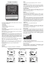
LEVEL: 
Indicates the level of loading selected from LEVEL 1 to LEVEL 24.

TIME/ WATT :
Indicates Time or Watt alternately. The time shows minutes and seconds. 
If preset, time counts downwards. Minimum preset 5Min. Range 5-99Min.  
The actually power display show in Watt. Preset range 30-350Watt only in 
Watt program P16.v Or permanently by pressing the F-key.

RPM/SPEED/KMH: 
Indicates  RPM  or  Speed  alternately.  The  RPM  display  shows  the  cycle 
turnings  per  minute.  The  speed  display  show  kilometers  per  hour.  Or 
permanently by pressing the F-key.

DIST/CAL: 
Indicates Distance or Calorie alternately.
The  distance  display  show  kilometer.  Preset  range  1-999km.  If  preset 
distance  counts  downwards.  The  calories  display  shows  kcal.  Minimum 
preset 10kcal. Preset range 10-990. Or permanently by pressing the F-key.

PULSE : 
Indicates the actually pulse heart rate. The whole set of heart rate detector 
include 2 sensors each side. Each sensor has 2 pieces of metal parts. The 
correct way to get detected is to gently hold both metal parts each hand. 
With the good signals picked up by the computer, the heart mark in the 
HEART RATE Display shall flash. Range 60-240bpm. If a pulse upper limit 
is specified, the display flashes when the preset value is reached.

TARGET H.R.:
Indicates only one value of TARGET HEART RATE.

LOADING Profiles:
There are 10 columns of loading bars, and 12 bars in each column. Each 
column represents 1 minute workout (without the change of TIME value), 
and each bar represents 2 levels of loading.

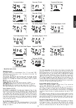
Program Graph:
Each graph shown is the profile of the loading in each interval (column). With 
the value of TIME counting up, each interval is 1 minute that all the columns 
make up 10 minutes. With the value of TIME counting down, each interval is 
the value of setup TIME divided by 10. For example, if the time value is setup
to  40  minutes,  each  interval  will  be  40  minutes  divided  by  10  intervals 
(40/10=4). Then, each interval will be 4 minutes. The following graphs are 
all the profiles in the monitor.

• Things You Should Know Before Exercising
The values calculated or measured by the computer are for exercise purpose 
only, not for medical purpose.

Programs Selection:
There are 22 programs 1 Manual Program, 10 Preset Programs, 4 Heart 
Rate Control Programs, 5 User Setting Programs, 1 Speed Independent 
Watt-Program, and 1 Pulse Recovery Measuring.

Computer Instructions

The monitor is designed for programmable magnetic bikes and introduced 
with the following categories:
- Key Functions
- About Displays
- Operating Ranges
- Things You Should Know Before Exercising
- Operation Instructions

• Key Functions
There are total 5 keys including START/STOP, FUNCTION(F), UP(+), DOWN(-
), and RECOVERY (TEST).

START/STOP: Starts or stops the program chosen. And, resets the monitor 
by pressing and holding for 2 seconds.

FUNCTION (F): Chooses or enters the functions from PROGRAMS, TIME, 
DISTANCE, WATT, CAL, TARGET HEART RATE, AGE, and 10 columns. The 
chosen function shall flash. Please note that not all the functions can be 
selected in every program according to the types of each program. During 
exercise, press the F-key to display the functions RPM, watts and calories 
or speed, time and distance permanently or alternately.

UP(+): Selects or increases the values of PROGRAMS, TIME, DISTANCE, 
WATT, CAL., TARGET HEART RATE, AGE, and 10 columns.

DOWN(-):  Selects  or  decreases  the  values  of  PROGRAMS,  TIME, 
DISTANCE, WATT, CAL., TARGET HEART RATE, AGE, and 10 columns.

RECOVERY(TEST): Starts the function of PULSE RECOVERY.

• About Display

PROGRAM:
Indicates the programs selected from PROGRAM 1 to PROGRAM 20


Manual Program 

Programm 1 Rolling 

Program 2 Valley


Programm 3 Fatburn 

Programm 4 Ramp 

Programm 5 Mountain

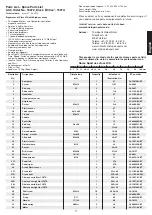
Summary of Contents for 15072

Page 1: ...1507A Notice de montage et d utilisation du No de commande 15072 1507A Assembly and exercise instructions for Order No 15072 1507A Montage en bedieningshandleiding voor Bestellnummer 15072 1507A GB D F NL RU Инструкция по монтажу и эксплуатации заказа 15072 1507A 1507A Silber 15072 Black Edition ...

Page 2: ... mit eingeschränkten physischen sensorischen oder geistigen Fähigkeiten oder Mangel an Erfahrung und Wissen verwendet werden wenn eine angemessene Aufsicht oder ausführliche Anleitung zur sicheren Benutzung des Gerätes sowie Aufklärung der evtl damit verbundenen Gefahren verstanden wurde Kinder dürfen nicht mit dem Heimsportgerät spielen Reinigungen und Wartungen sollten nicht von Kindern ohne Auf...

Page 3: ...3 Deutsch ...

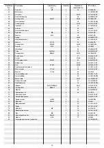
Page 4: ...n ET Nummer Nr mm Stück Abbildungs Nr 1 Computer 1 67 36 1507203 BT 2 Schraube M5x12 4 1 67 39 9903 3 Stopfen 25 2 5 39 9847 4 Pulskabel 2 1 6 36 1122 09 BT 5 Lenker 1 67 33 1105 06 SI 6 Pulssensor 2 5 36 9806206 BT 7 Griffüberzug 2 5 36 1410 04 BT 8 Schraube M4x15 2 5 6 39 9909 SW 9 Lenkerverkleidung 1 67 36 9103 07 BT 10 Distanzstück 8x13x48 1 11 36 9613209 BT 11 Lenkerschraube M8x75 1 67 36 921...

Page 5: ...9 CR 55 Abdeckkappe 2 27 36 9840 15 BT 56 Schraube 2 27 60 39 9886 CR 57 Schraube M4x25 6 28 39 9825338 BT 58 Gummiring 1 28 39 36 1507 11 BT 59 Flachriemen 380J6 1 42 60 36 9103 21 BT 60 Tretachse mit Riemenscheibe 1 33 33 1507 12 BT 61 Wellscheibe 17 22 1 60 36 9918 22 BT 62 Unterlegscheibe 17 22 1 62 39 10135 63 Fußkappe mit Transportrolle 2 64 36 1507 13 BT 64 Fuß vorne 1 39 33 1507 04 SW 65 S...

Page 6: ...rung des Gerätes bei Unebenheiten gedacht Schritt 2 Montage der Pedale 25L 25R 1 Montieren Sie die Pedalsicherungsbänder an die entsprechenden Pedalen 25L 25R Die Pedalsicherungsbänder sind markiert mit R für Rechts und L für Links 2 Montieren Sie die Pedalen 25L 25R an die Pedalarme 27L 27R Die Pedale sind markiert mit R für Rechts und L für Links Achtung Links und Rechts sind aus der Richtung zu...

Page 7: ...nn zieht das Sattelstützrohr in die neue Position bringt bis der Schnellverschluss einrastet und Ihn danach wieder festdreht 2 Legen Sie den Sattelgleiter 13 in die Aufnahme am Sattelstützrohr 15 ein und befestigen Sie diesen in gewünschter horizontaler Stellung mittels der Schraube M10x35 69 Unterlegscheibe 23 und Sterngriffmutter 24 am Sattelstützrohr 15 3 Stecken Sie den Sattel 12 auf den Satte...

Page 8: ...Stützrohr 67 ohne die Kabel verbindung einzuquetschen und schrauben Sie den Computer 1 mittels der Schrauben 2 an dem Stützrohr 67 fest Die Schrauben 2 befinden sich dazu auf der Computerrückseite Schritt 8 Kontrolle 1 Alle Verschraubungen und Steckverbindungen auf ordnungsgemäße Montage und Funktion prüfen Die Montage ist hiermit beendet 2 Wenn alles in Ordnung ist mit leichten Widerstandseinstel...

Page 9: ...setzen sie sich dabei auf den Sattel Dabei mit den Händen am Lenker festhalten und führen Sie dann den anderen Fuß auf das zweite Pedal unter das Pedalsicherungsband Benutzung Halten Sie sich mit beiden Händen an dem Lenker in gewünschter Position fest und bleiben Sie auf dem Sattel während des Trainings sitzen Ebenso darauf achten dass die Füße auf den Pedalen mit den Pedalsiche rungsbändern gesi...

Page 10: ...TT 80RPM WATT 90RPM WATT 100RPM WATT 1 8 12 18 24 30 36 45 56 72 2 10 16 25 32 39 45 60 75 90 3 12 20 30 40 49 57 75 84 108 4 14 24 36 48 58 69 90 101 126 5 16 28 43 56 68 81 105 108 144 6 28 32 49 65 78 92 120 124 162 7 20 36 55 72 88 103 135 140 180 8 22 40 62 78 97 115 150 157 198 9 24 44 70 84 107 127 165 173 216 10 25 48 76 91 117 139 180 189 234 11 28 52 83 99 126 151 195 204 252 12 31 56 88...

Page 11: ...vorgegebenen individuellen Ziel pulses Einstellbereich Puls 60 240 Widerstandsprofil Die gewünschte Trainingsdauer kann im Bereich ZEIT voreingestellt werden Diese voreingestellte Zeit wird vom System in 10 Teilintervalle unterteilt Jeder Balken auf der Zeitachse horizontal 1 10 der vorgegebenen Zeit z B Trainingszeit 5 min jeder Balken ist 30 Sek Trainingszeit 10 min jeder Balken 1 min Jeder der ...

Page 12: ...lken zeigt die Belastung an nicht ein Geländeprofil Programm 6 Intervall Programm 7 Cardio Programm 8 Plateau Programm 9 Treppe Programm 10 Rally User Setting Program 11 U1 User Setting Program 12 U2 User Setting Program 13 U3 User Setting Program 14 U4 User Setting Program 15 U5 Programm 16 Watt Control Program Programm 17 HRCP Programm 18 HRCP Programm 19 HRCP Programm 20 HRCP Programmabläufe we...

Page 13: ...ton erscheinen wenn die Verkabelung feh lerhaft angeschlossen ist oder es eine Störung in der Widerstandseinstellung gibt Überprüfen Sie alle Kabelverbindungen besonders an den Steckern Nach Behebung des Fehlers die Start Stop Taste 2 Sek gedrückt halten um das System auf 0 zurückzusetzen PULSMESSUNG 1 Handpulsmessung Im linken und rechten Lenkergriffteil ist je eine Metallkontaktplatte die Sen so...

Page 14: ...er Lenkerbefestigungsschraube sowie an das Gewinde des Schnellverschlusses geben Störungsbeseitigung Wenn Sie die Funktionsstörung nicht anhand der aufgeführten Informationen beheben können so kontaktieren Sie Ihren Händler oder den Hersteller Problem Mögliche Ursache Lösung Der Computer schaltet sich durch Drücken einer Taste nicht ein Kein Netzteil ein gesteckt oder die Steckdose führt keine Spa...

Page 15: ... Körpertemperatur und die Sauerstoffzufuhr langsam gesteigert werden Dieses ist durch gymnastische Übungen über eine Dauer von fünf bis zehn Minuten möglich Danach sollte das eigentliche Training Trainings Phase beginnen Die Trainingsbelastung sollte erst einige Minuten gering sein und dann für eine Periode von 15 bis 30 Minuten so gesteigert werden daß sich der Puls im Bereich zwischen 70 und 85 ...

Page 16: ...ilities or lack of experience and knowl edge if they have been given supervision or instruction concerning use of the appliance in a safe way and understand the hazards involved Children shall not play with the appli ance Cleaning and user maintenance shall not make by children without supervision Take suitable measures to ensure that children never use the machine without supervision 14 The appli...

Page 17: ... cable 2 1 6 36 1122 09 BT 5 Handlebar 1 67 33 1105 06 SI 6 Hand pulse sensor 2 5 36 9806206 BT 7 Grip foam 2 5 36 1410 04 BT 8 Screw M4x15 2 5 6 39 9909 SW 9 Plastic cover 1 67 36 9103 07 BT 10 Tube spacer 8x13x48 1 11 36 9613209 BT 11 T Knob M8x75 1 67 36 9211 16 BT 12 Saddle 1 13 36 9806210 BT 13 Seat slide 1 15 33 9806206 SI 14 End cap 20x60 2 15 36 9806211 BT 15 Seat post 1 13 36 33 1507 05 S...

Page 18: ...w 2 27 60 39 9886 CR 57 Self tapping screw M4x25 6 28 39 9825338 BT 58 Rubber ring 1 28 39 36 1507 11 BT 59 Belt 380J6 1 42 60 36 9103 21 BT 60 Pedal axle with belt wheel 1 33 33 1507 12 BT 61 Wave washer 17 22 1 60 36 9918 22 BT 62 Washer 17 22 1 62 39 10135 63 Front stabilizer cap 2 64 36 1507 13 BT 64 Front stabilizer 1 39 33 1507 04 SW 65 Motor cable 1 34 65 36 1107207 BT 66 Connection cable 1...

Page 19: ... can adjust the height at rear caps 38 and secure for stable position Step 2 Attach the pedals 25L 25R 1 Attach the pedal straps to the pedals 25L 25R The pedal strap and pedals are marked with L for left and R for right 2 The pedals 25L 25R are marked with R for right and L for left NOTE Right and Left are specified as viewed seated on the machine during training Connect each pedal 25L 25R to the...

Page 20: ...cap of the lock must be pulled away and the saddle adjusted Then secure the new setting by tightening the quick release 20 2 Place the seat slide 13 into the holder of saddle support 15 set it at the desired horizontally position and tighten it by using Screw M10x35 69 washer 23 and hand grip nut 24 3 Push the saddle 12 with saddle bracket into the movable saddle slide 13 and tight it up into desi...

Page 21: ...sert the plug of adaptor 68 into the jack 37 of chain guard 28 2 Please insert the adaptor 68 to the jack of wall power 230V 50Hz Step 8 Checks 1 Check the correct installation and function of all screwed and plug connections Installation is thereby complete 2 When everything is in order familiarise yourself with the machine at a low resistance setting and make your individual adjustments Note Ple...

Page 22: ... the desired position and tighten them after adjustment again firmly To avoid any problems such as back knee pain or numbness in the feet through bad seat position on the bike the maintenance of a proper adjust ment of the saddle and handlebar we strongly recommend Mount Use Dismount Mount a After the seat is adjusted to properly position insert your foot into retaining strap of pedal step on the ...

Page 23: ...ATT 1 8 12 18 24 30 36 45 56 72 2 10 16 25 32 39 45 60 75 90 3 12 20 30 40 49 57 75 84 108 4 14 24 36 48 58 69 90 101 126 5 16 28 43 56 68 81 105 108 144 6 28 32 49 65 78 92 120 124 162 7 20 36 55 72 88 103 135 140 180 8 22 40 62 78 97 115 150 157 198 9 24 44 70 84 107 127 165 173 216 10 25 48 76 91 117 139 180 189 234 11 28 52 83 99 126 151 195 204 252 12 31 56 88 105 136 163 210 221 270 13 33 60...

Page 24: ...wn each interval is the value of setup TIME divided by 10 For example if the time value is setup to 40 minutes each interval will be 40 minutes divided by 10 intervals 40 10 4 Then each interval will be 4 minutes The following graphs are all the profiles in the monitor Things You Should Know Before Exercising The values calculated or measured by the computer are for exercise purpose only not for m...

Page 25: ... are free to edit the values in the order of TIME DISTANCE CAL and the level of loading in 10 intervals The values and profiles will be stored in the memory after setup After pressing START STOP key to exercise please also apply the heart rate detector appropriately Users may also change the ongoing loading in each interval by pressing or key and they will not change the level of loading stored in...

Page 26: ...ot switch on after start cycling Sensor impulse missing base on not correct posi tion of sensor Take off the cover and check the distance between magnet and Sensor The magnet at turning belt wheel should have only less than 5mm distance against the sensor position No pulse value Pulse cable is not plugged in Check the separately pulse cable is well connected with computer No pulse value Pulse sens...

Page 27: ...ten minutes Then the actual training training phase should begin The training exertion should be relatively low for the first few minutes and then raised over a period of 15 to 30 minutes such that the pulse rate reaches the region of between 70 to 85 of the maximum pulse rate In order to support the circulation after the training phase and to prevent aching or strained muscles later it is necessa...

Page 28: ...et les personnes ayant des capacités physiques sensorielles ou mentales réduites ou manque d expérience et de connaissances si approprié surveillance ou d instructions détaillées pour l utilisation sûre de l appareil ainsi que l éducation des dangers éventuellement associés a été entendu Les enfants ne peuvent pas jouer avec le matériel de sport à domicile Nettoyage et entretien ne devraient pas ê...

Page 29: ... Désignation Dimensions Quantité Monté sur Numéro ET n en mm Unités schéma n 1 Ordinateur 1 67 36 1507203 BT 2 Vis M5x12 4 1 67 39 9903 3 Bouchon ronde 25 2 5 39 9847 4 Faisceau de fils de mesure du pouls 2 1 6 36 1122 09 BT 5 Guidon 1 67 33 1105 06 SI 6 Unité à poignée de mesure du pouls 2 5 36 9806206 BT 7 Revêtement de guidon 2 5 36 1410 04 BT 8 Vis M4x15 2 5 6 39 9909 SW 9 Revêtement de guidon...

Page 30: ...9 10269 CR 55 Bouchon ronde 2 27 36 9840 15 BT 56 Vis 2 27 60 39 9886 CR 57 Vis M4x25 6 28 39 9825338 BT 58 Rondelle de caoutchouc 1 28 39 36 1507 11 BT 59 Courroie trapézoïdale 380J6 1 42 60 36 9103 21 BT 60 Roue à courroie avec axe de pédalier 1 33 33 1507 12 BT 61 Rondelle vague 17 22 1 60 36 9918 22 BT 62 Rondelle 17 22 1 62 39 10135 63 Chapeaux finaux avec roulette de transport 2 64 36 1507 1...

Page 31: ...d inégalité Etape n 2 Montage des pédales 25R 25L 1 Montezlesbandesdesécuritédepédalesurlespédalescorrespondantes Le band de sécurité droite est marquée d un R et le band de sécurité gauche est marquée d un L 2 Montez les pédales 25R 25L sur les bras de manivelle 27L 27R La pédale droite est marquée d un R et la pédale gauche est marquée d un L Attention la direction de visée est à droite et à gau...

Page 32: ... du réglage de la position souhaitée la position d ajustement A la plus haute qui est marquée en couleur 2 Placez le chariot de selle 13 dans le logement au niveau du tube support de selle 15 et fixez le en position horizontale à l aide de la vis M10x35 69 de écrou poignée étoile 24 et de la rondelle 23 3 Placez la selle 12 avec le logement de selle sur le chariot de selle 13 et serrez le à bloc d...

Page 33: ...reil en effectuant de légers réglages de la résistance et effectuer les réglages individuels Remarques Veuillez à conserver soigneusement le jeu d outils ainsi que les instructions de montage dont vous aurez éventuellement besoin ultérieurement pour effectuer les réparations nécessaires et commander des pièces de rechange Etape n 6 Montage de l ordinateur 1 sur le tube de support de guidon 67 1 Br...

Page 34: ...n désirée et serrez les après ajustement de nouveau fermement Pour des problèmes tels que maux de dos genou ou engourdissement dans les pieds empêché par un manque de place assise sur la moto le maintien d un bon réglage de la selle et le guidon est fortement recommandée Monter utiliser descendre Monter a Après avoir réglé la selle dans la position désirée placez votre pied dans la bande de la péd...

Page 35: ...T 90RPM WATT 100RPM WATT 1 8 12 18 24 30 36 45 56 72 2 10 16 25 32 39 45 60 75 90 3 12 20 30 40 49 57 75 84 108 4 14 24 36 48 58 69 90 101 126 5 16 28 43 56 68 81 105 108 144 6 28 32 49 65 78 92 120 124 162 7 20 36 55 72 88 103 135 140 180 8 22 40 62 78 97 115 150 157 198 9 24 44 70 84 107 127 165 173 216 10 25 48 76 91 117 139 180 189 234 11 28 52 83 99 126 151 195 204 252 12 31 56 88 105 136 163...

Page 36: ...5 minutes Il est possible de paramétrer la durée de 5 à 99 min L ordinateur doit d abord convertir les watts L ordinateur calcule exactement l effort fait pendant l entraînement Les résultats s affichent en watts L affichage de la valeur cible se fait dans le programme Il est possible de paramétrer les watts de 30 à 350 min Changement d affichage automatique de la durée et de watts Ou en permanenc...

Page 37: ...ran Display Le déroulement de chaque programme suit la représentation du diagramme des leviers dans la zone d affichage par exemple le pro gramme 3 montagne vallée dans ce cas la hauteur des leviers la résistance la durée étant répartie sur la largeur des leviers Après le paramétrage du programme il faut impérativement appuyer sur La touche Start Stop pour commencer l entraînement Les valeurs étab...

Page 38: ... Mesure des pulsations à la poignée La poignée de maintien comportent chacune un capteur pièces de contact métalliques Connectez le câble à la prise de l ordinateur Attention veillez à ce que la paume de vos mains repose simultanément sur les capteurs avec une pression normale Dès que les pulsations sont enregistrées un cœur apparaît en surbrillance à côté de l affichage des pulsations La mesure d...

Page 39: ... roulements de la pédale gauche et à droite au fil de la vis de fixation du guidon et sur les filets de la libération rapide Corrections Si vous ne pouvez pas résoudre en utilisant les informations énumérées à l dysfonctionnement s il vous plaît contactez votre revendeur ou fabricant Problème Cause Possible Solution L ordinateur ne s allume pas en appuyant sur un bouton Aucun adapta teur de couran...

Page 40: ...possible en effectuant de la gymnastique pendant cinq à dix minutes L entraînement proprement dit phase d entraînement devant commen cer ensuite Choisir une faible résistance pendant quelques minutes puis accroître entre 15 et 30 minutes de sorte que le pouls se situe entre 70 et 85 de son maximum Afin de faciliter la circulation après la phase d entraînement et d éviter des courbatures ou des mus...

Page 41: ... borstpijn en an dere abnormale symptomen ondervonden worden de training vroegtijdig beëindigen en u tot een geschikte geneesheer wenden 13 Over het algemeen geldt dat sporttoestellen geen speelgoed zijn Dit apparaat kan worden gebruikt door kinderen van 8 jaar en personen met verminderde lichamelijke zintuiglijke of verstandelijke vermogens of gebrek aan ervaring en kennis indien geschikt toezich...

Page 42: ...eerd aan ET nummer nr mm stuks afbeeldingsnr 1 Computer 1 67 36 1507203 BT 2 Schroef M5x12 4 1 67 39 9903 3 Ronde dop 25 2 5 39 9847 4 Pulskabel 2 1 6 36 1122 09 BT 5 Stuur 1 67 33 1105 06 SI 6 Handpulseenheid 2 5 36 9806206 BT 7 Stuur overtrek 2 5 36 1410 04 BT 8 Schroef M4x15 2 5 6 39 9909 SW 9 Stuurbekleding 1 67 36 9103 07 BT 10 Afstandsstuk 8x13x48 1 11 36 9613209 BT 11 Fleugelschroef M8x75 1...

Page 43: ...ekkap 2 27 36 9840 15 BT 56 Schroef 2 27 60 39 9886 CR 57 Schroef M4x25 6 28 39 9825338 BT 58 Rubberenring 1 28 39 36 1507 11 BT 59 Vlakke riem 380J6 1 42 60 36 9103 21 BT 60 Pedaalkruk as wiel 1 33 33 1507 12 BT 61 Schijf golfen 17 22 1 60 36 9918 22 BT 62 Onderlegplaatje 17 22 1 62 39 10135 63 Voetkappen met Transportrolleneenheid 2 64 36 1507 13 BT 64 Voorste voetbuis 1 39 33 1507 04 SW 65 Moto...

Page 44: ...dop moeren 35 De hoogtecompensatieschroeven 38 zijn voorzien om het toestel in geval van oneffenheden te stabiliseren Stap 2 Montage van de pedalen 25L 25R 1 Monteer de pedaalvastzetbanden op de desbetreffende pedalen 25L 25R De pedaalvastzetbanden zijn gemarkeerd met R voor rechts en L voor links 2 Monteer de pedalen 25L 25R op de krukarmen 27L 27R De pedalen zijn gemarkeerd met R voor rechts en ...

Page 45: ...gewenste positie niet verder uit het onderstel wordt getrokken dan de hoogste instelpositie die met een kleur is gemarkeerd 2 Legt de zadelglijder 13 in de houder aan het zadelsteunbuis 15 en bevestigd u deze in de gewenste horizontale positie met de sterförmige greepmoer 24 en de onderlegplaatje 23 3 Bevestigd u het zadel 12 op de zadelglijder 13 en schroeft u deze in de gewenste kantelen positie...

Page 46: ... het nettoestel 68 in de desbetreffende bus 37 op het achterste uiteinden van de bekleding 28 2 Steek daarna het nettoestel 68 in een contactdoos 230V 50Hz Stap 8 Controle 1 Alle schroef en stekkerverbindingen op een correcte montage en juiste werking controleren Daarmee is de montage beëindigd 2 Wanneer alles in orde is met lichte weerstandsinstellingen vertrouwd raken met het apparaat en de indi...

Page 47: ...raai ze na aanpassing opnieuw stevig Om problemen zoals rug knie pijn of gevoelloosheid in de voeten voorko men door een gebrek aan zitpositie op de fiets het behoud van een juiste afstelling van het zadel en het stuur wordt sterk aanbevolen De Opstappen Gebruiken en Afstappen Opstappen a Nadat u de zitting op de juiste hoogte hebt afgesteld plaatst u uw voet op de voetsteun onder het riempje en h...

Page 48: ...RPM WATT 100RPM WATT 1 8 12 18 24 30 36 45 56 72 2 10 16 25 32 39 45 60 75 90 3 12 20 30 40 49 57 75 84 108 4 14 24 36 48 58 69 90 101 126 5 16 28 43 56 68 81 105 108 144 6 28 32 49 65 78 92 120 124 162 7 20 36 55 72 88 103 135 140 180 8 22 40 62 78 97 115 150 157 198 9 24 44 70 84 107 127 165 173 216 10 25 48 76 91 117 139 180 189 234 11 28 52 83 99 126 151 195 204 252 12 31 56 88 105 136 163 210...

Page 49: ...uter meet exact het ter gelegen heid van de training behaalde prestatievermogen De weergave gebeurt in watt In het programma 16 volgt hier de weergave van de beoogde waar de De voorafgaande invoer kan van 30 tot 350 Watt ingevoerd worden Weergave schakelt automatisch tussen tijd en watt Of permanent door op de F toets RPM SPEED Weergave van pedaalomwentelingen per minuut en snelheid in km h Weerga...

Page 50: ...rogramma s gebeurt in overeenstemming met de weergave van het balk diagram in het displayveld bijvoorbeeld programma 3 berg dal enz daarbij is de balkhoogte weerstand de tijd wordt over de balkbreedte verdeeld Na programma instelling onvoorwaardelijk toets START STOP indrukken wanneer er met de training gestart wordt In principe zijn al de vastgestelde en weergegeven waarden niet ge schikt voor ge...

Page 51: ...rstand doet niet Controleer al de kabelverbindingen meer in het bijzonder aan de stekkers Na oplossing van de fout de toets S 2 seconden lang ingedrukt houden om het systeem terug op 000 te zetten POLSSLAGMETING 1 Handpulsmeting In het linkse en rechtse stuurgedeelte is telkens een metalen contactplaat de voelers voorzien Verbind de kabel met de computer Gelieve erop te letten dat steeds beide han...

Page 52: ...n het stuur bevestigingsbout en op de schroefdraad van de zadel sluitschroef Fixes Als u niet kunt oplossen met behulp van de genoemde storing informatie kunt u contact opnemen met uw dealer of Fabrikant Probleem Mogelijke oor zaak Oplossing De computer wordt niet inge schakeld door het indrukken van een knop Geen stroom ad apter is geplaatst of de socket is niet leven Controleer of de adapter cor...

Page 53: ...nnen De trainingsbelasting moet de eerste minuten laag zijn en dan gedurende een periode van 15 tot 30 minuten zo toenemen dat de hartslag zich tussen de 70 en 85 van de maximale hartslag bevindt Om de bloedsomloop na de trainingsfase te ondersteunen en om spierpijn of verrekte spieren te voorkomen moet de trainingsfase door een cooling down worden gevolgd Hierbij moeten vijf tot tien minuten lang...

Page 54: ...водстве не указано иного то тренажером может пользоваться только один человек Время тренировки не должно было превосходить в целом 60 Min ежедневно 11 Необходимо носить тренировочную одежду и обувь которые подходят для оздоровительной тренировки на тренажере Одежда должна такой чтобы по своей форме например длине она не могла зацепиться во время тренировки Следует подбирать тренировочную обувь кот...

Page 55: ...4 см Наименование Размеры в мм Кол во Монтируется на ЕТ картинки штук 1 Компьютер 1 67 36 1507203 BT 2 Болт M5x12 4 1 67 39 9903 3 Заглушки 25 2 5 39 9847 4 Кабель измерителя пульса 2 1 6 36 1122 09 BT 5 Руль 1 67 33 1105 06 SI 6 Датчик измерителя пульса 2 5 36 9806206 BT 7 Оболочка руля 2 5 36 1410 04 BT 8 Болт M4x15 2 5 6 39 9909 SW 9 Обшивка руля 1 67 36 9103 07 BT 10 Промежуточное тело 8x13x48...

Page 56: ...R 55 Заглушки 2 27 36 9840 15 BT 56 Болт 2 27 60 39 9886 CR 57 Болт M4x25 6 28 39 9825338 BT 58 Резиновое кольцо 1 28 39 36 1507 11 BT 59 Плоский ремень 380J6 1 42 60 36 9103 21 BT 60 Шайба шатуна Ось шатуна 1 33 33 1507 12 BT 61 Гнутая подкладная шайба 17 22 1 60 36 9918 22 BT 62 Подкладная шайба 17 22 1 62 39 10135 63 Задняя ножка 2 64 36 1507 13 BT 64 Передняя ножка 1 39 33 1507 04 SW 65 Кабель...

Page 57: ... Вы предупредите непреднамеренные движения тренажера во время тренировки Шаг 2 Монтаж педалей 25R 25L 1 Установите фиксирующие ленты педалей на соответствующие педали 25R 25L 2 Установите педали 25R 25L на рычаги педалей 27L 27R Педали имеют маркировку R для правой и L для левой Внимание Левая и правая сторона подразумеваются при нахождении на тренажере в момент тренировки Правая педаль 25R должна...

Page 58: ...йся затвор 20 установите опорную трубу седла в новую позицию до защелкивания быстрозакрывающегося затвора после чего снова крепко закрутите быстрозакрывающийся затвор 2 Вложите салазки седла 13 в крепление на опорной трубе седла 15 и зафиксируйте их в желаемом горизонтальном положении с помощью болта M10x35 69 Грибковая гайка 24 и подкладной шайбы 23 на опорной трубе руля 15 3 Вставьте седло 12 на...

Page 59: ...ькой нагрузке и индивидуально настройте тренажер Замечание Пожалуйста сохраняйте набор инструментов для последующих возможных ремонтов и инструкцию по монтажу для возможных заказов запасных частей Шаг 6 Монтаж компьютера 1 на опорную трубу 67 1 Вставьте соединительный кабель 66 и кабель датчика пульса 4 в соответствющие гнезда компьютера 1 2 Вставьте компьютер 1 в опорной трубе 67 обратите внимани...

Page 60: ...енения положения руля ослабьте быстродействующий затвор измените положе ние руля и снова крепко заверните быстродействующий затвор Чтобы предотвратить возможные боли в коленях и в спине из за неправильного положения тела мы рекомендуем уделить внимание правильному положению седла и руля Садиться и спускаться с тренажера Садиться на тренажер После установления правильной высоты седла возьмитесь за ...

Page 61: ...5 60 75 90 3 12 20 30 40 49 57 75 84 108 4 14 24 36 48 58 69 90 101 126 5 16 28 43 56 68 81 105 108 144 6 28 32 49 65 78 92 120 124 162 7 20 36 55 72 88 103 135 140 180 8 22 40 62 78 97 115 150 157 198 9 24 44 70 84 107 127 165 173 216 10 25 48 76 91 117 139 180 189 234 11 28 52 83 99 126 151 195 204 252 12 31 56 88 105 136 163 210 221 270 13 33 60 92 113 145 175 225 238 288 14 36 64 96 121 155 18...

Page 62: ...ляет 5 мин Устанавливается от 5 до 99 мин Компьютер точно измеряет роизведенную в ходе тренировки работу Индикация производится в ваттах В программе 16 производится индикация целевого значения Устанавливается от 30 до 350 ватт Автоматическое изменение отображенияTIME время и WATT ватт Или постоянно нажав клавишу F RPM ОБ мин SPEED km h СКОРОСТЬ км час Индикация оборотов педалей в минуту и скорости...

Page 63: ...ение программы показываются на дисплее графически Каждая программа протекает по указанной схеме на дисплее например программа 3 гора низина и т д при этом высота сегмента нагрузка время распределяется по всей шкале После настройки программы обязательно перед началом тренировки нажать клавишу Start Stop Manual Program Programm 1 Rolling Program 2 Valley Programm 3 Fatburn Programm 4 Ramp Programm 5...

Page 64: ...ак чтобы тренировочный пульс оставался в области выбранного режима Программа 20 Целевое значение пульса THF Здесь вы можете задать оптимальный показатель частоты биения сердца THF и компьютер с учетом определенных допусков удерживает эту нагрузку в заданном вами пределе 60 240 пульса СПИСОК ВОЗМОЖНЫХ НЕИСПРАВНОСТЕЙ После каждого нового старта компьютер проводит быстрый тест на функциональность При...

Page 65: ...резьбу винта руля и быстродействующего затвора маслом из распылителя Исправление неполадок Если проблема не может быть решена с помощью нижестоящих указаний пожалуйста обратитесь в центр где вы купили тренажер Проблема Возможная причина Решение Компьютер не включается посредством нажатия на любую клавишу Не подключен блок питания или в сети нет напряжения Проверьте подключен ли блок питания надлеж...

Page 66: ...сь за локоть и потяните до ощущения растяжения трицепса Останьтесь в этом положении на 20 секунд повторите другой рукой Наклонитесь вперед не сгибая ног и попытайтесь достать пальцами рук до пола Выполняйте упражнение 2 раза по 20 секунд Сядьте на пол и вытяните одну ногу Наклонитесь вперед и попробуйте достать ступню Выполняйте упражнение 2 раза по 20 секунд В положении широкого выпада обопритесь...

Page 67: ... поддержания его нормальной физической формы Трехразовые тренировки необходимы для улучшения Вашей физической формы и уменьшения веса Идеальная частота тренировок 5 раз в неделю 3 Планирование тренировок Каждая тренировка должна состоять из трех фаз разогрев разминка непосредственно тренировка и остывание после тренировки заключительная фаза Температура тела и поступление кислорода в организм долж...

Page 68: ...w christopeit sport com Fax 49 0 2051 6067 44 D 42551 Velbert http www christopeit sport net by Top Sports Gilles GmbH D 42551 Velbert Germany Service Hersteller Bei Reklamationen notwendigen Ersatzteilbestellungen oder Reparaturen wenden Sie sich bitte an unsere Service Abteilung Internet Service und Ersatzteilportal www christopeit service de ...

Reviews: