background image

2-2

M Series User Manual

020-100009-05  Rev. 1  (09-2010)

Section 2: Installation and Setup

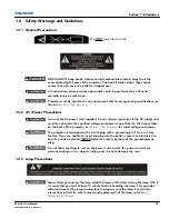
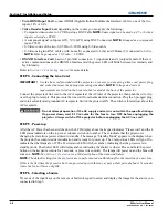
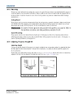
2. Align the lens interface plate with the lens mount. Align the lens electrical connector with the mating 

connector on the lens mount. Fully insert the assembly straight into the lens mount opening without 
turning. Press using your hand as shown in 

Figure 2-2 Lens Placement

NOTE:


When installing the lens, 

ensure that the lens is not inserted at an angle, as this can cause damage.

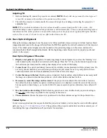
3. Remove the front lens cap.
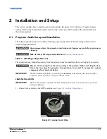
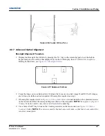
4. While holding the lens flat against the lens mount, rotate the lens clamp clockwise to lock the lens 

assembly in place. See 

Figure 2-3 

Figure 2-4

.

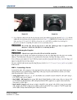
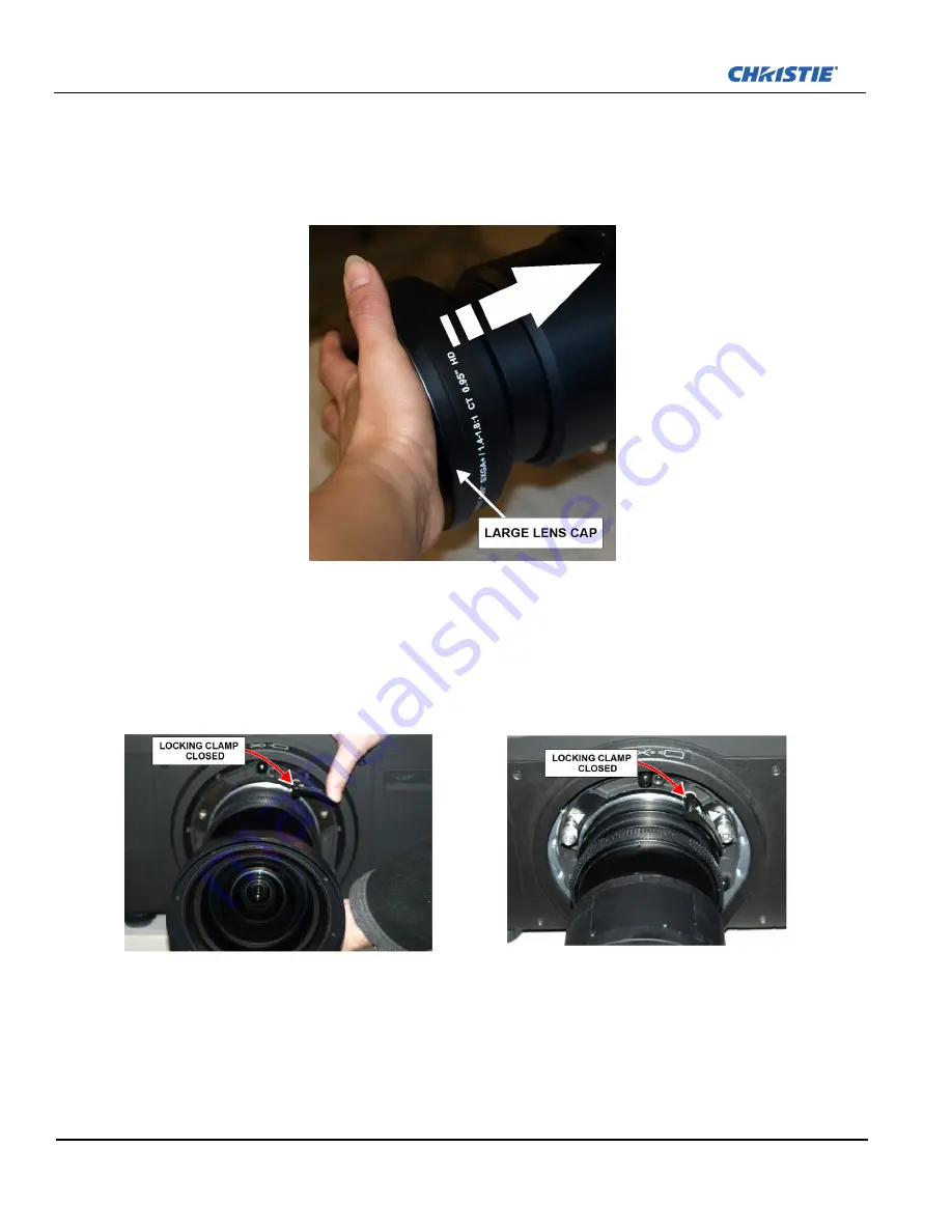
5. For added stability such as motion applications, fasten the security screws provided with the lens-mount. 

NOTE:

 There are two types of lens plate models. See 

Figure 2-5

 & 

Figure 2-6

.

F

IGURE 

2-2 L

ENS 

P

LACEMENT

F

IGURE 

2-3 F

IGURE 

2-4 

Summary of Contents for M Series

Page 1: ...M Series U S E R M A N U A L 020 100009 05 ...

Page 2: ......

Page 3: ...M Series U S E R M A N U A L 020 100009 05 ...

Page 4: ...h high quality materials and components that can be recycled and reused This symbol means that electrical and electronic equipment at their end of life should be disposed of separately from regular waste Please dispose of the product appropriately and according to local regulations In the European Union there are separate collection systems for used electrical and electronic products Please help u...

Page 5: ...ns 2 7 2 2 3 Projector Position and Mounting 2 10 2 2 4 Mounting 2 15 2 2 5 Adjusting Projector Height Tilt 2 15 2 2 6 Basic Optical Alignment 2 16 2 2 7 Advanced Optical Alignment 2 17 2 2 8 Powering Down 2 19 2 2 9 Connecting Communications 2 20 2 2 10 Projector Communications 2 25 2 3 Connecting Sources 2 26 3 Operation 3 1 Using the Remote Keypad or Built In Keypad 3 1 3 1 1 Remote Keypad Comm...

Page 6: ...ns 5 2 5 2 2 Cleaning the Lens 5 3 5 3 Replacing the Lamps 5 3 6 Troubleshooting 6 1 Power 6 1 6 1 1 Projector Does Not Power ON 6 1 6 2 Lamp 6 1 6 2 1 Lamp Does Not Ignite 6 1 6 2 2 Lamp Suddenly Turns OFF 6 2 6 2 3 Flicker Shadows Or Dimness 6 2 6 3 LCD 6 2 6 3 1 Blank Screen No Menu Displaying 6 2 6 4 Remote Keypad 6 2 6 4 1 Remote Keypad Does Not Seem to Work 6 2 6 5 OSD 6 3 6 5 1 The OSD Menu...

Page 7: ...l Format 7 1 7 1 2 Brightness ANSI Lumens 7 1 7 1 3 Contrast 7 2 7 1 4 Luminance Uniformity 7 2 7 1 5 Color Uniformity 7 2 7 1 6 Color Primaries 7 2 7 1 7 Gamma 7 2 7 1 8 Grayscale Color Resolution 7 2 7 1 9 Color Temperature 7 3 7 1 10 Convergence 7 3 7 1 11 Blemishes 7 4 7 1 12 Pixel Defects 7 4 7 1 13 Image Artifacts 7 4 7 1 14 Picture Centering with 1 4 1 8 1 HD lens 7 4 7 2 Feature Set 7 4 7 ...

Page 8: ...5 9 AMX Crestron Support 7 10 7 6 Power Requirements 7 11 7 6 1 Lamp Specification 7 12 7 7 Physical Specifications 7 12 7 7 1 Size 7 12 7 7 2 Adjustment 7 12 7 7 3 Weight 7 12 7 7 4 Operating Position 7 12 7 8 Reliability and Serviceability 7 12 7 8 1 Reliability 7 12 7 8 2 Serviceability 7 12 7 9 Environment 7 13 7 9 1 Temperature Humidity Altitude 7 13 7 10 Accessories and Service Components 7 ...

Page 9: ...stallation and Setup Section 3 Operation Section 4 Web User Interface Section 5 Maintenance Section 6 Troubleshooting Section 7 Specifications Appendix A Menu Tree Appendix B GPIO Appendix C DMX ArtNet DISCLAIMER Every effort has been made to ensure the information in this document is accurate and reliable However due to constant research the information in this document is subject to change witho...

Page 10: ...es appear in Courier font For example No Signal Present Login christiedigital Error codes LED status codes appear bold e g LP A1 etc Operational states of modules appear capitalized such as power ON OFF 1 2 Purchase Record and Service Contacts Whether the projector is under warranty or the warranty has expired Christie s highly trained and extensive factory and dealer service network is always ava...

Page 11: ...face Overview The projector can be controlled via a menu system displayed on the image The menu system can be controlled by an IR remote wired remote or through the built in keypad The LCD screen and built in keypad allow some functions to be controlled without the need of an OSD display and provide a quickly accessible interface to view error reporting The functions on the OSD can also be control...

Page 12: ... constant brightness maintenance Intelligent Lens System ILS Motorized lens mount for all models Auto setup feature Integrated ChristieNET Networking ability through RS 232 and RS 422 connectors Status LED display on built in keypad for easy projector status monitoring Control with remote keypad wired remote or built in keypad Four input slots for Optional Input Modules Refer to Section 7 Specific...

Page 13: ...ower range Refer to the license label on the back of the projector or Section 7 Specifications for rated voltage and power The projector is equipped with a 3 wire plug with a grounding pin This is a safety feature If you are unable to insert the plug into the outlet contact an electrician to have the outlet replaced NEVER defeat the safety purpose of the grounding type plug Do not allow anything t...

Page 14: ......

Page 15: ...y Warnings and Guidelines in Section 5 Maintenance STEP 1 Installing a Projection Lens The projection lens shipped separately from the projector must be installed prior to setting up the projector Remove the lens plug from the lens opening in the projector before installing the lens Retain the lens plug for projector transportation to protect the projector s optical components from dust and debris...

Page 16: ...n Figure 2 2 Lens Placement NOTE When installing the lens ensure that the lens is not inserted at an angle as this can cause damage 3 Remove the front lens cap 4 While holding the lens flat against the lens mount rotate the lens clamp clockwise to lock the lens assembly in place See Figure 2 3 Figure 2 4 5 For added stability such as motion applications fasten the security screws provided with the...

Page 17: ...th the projector positioned perpendicular to the screen the image will appear rectangular instead of keystoned For more detailed instructions on positioning the projector refer to 2 2 3 Projector Position and Mounting later in this section STEP 3 Connecting a Source Located at the back of the projector is the input panel where all source connections are made Each input is clearly labeled for easy ...

Page 18: ...nection Plug the 3 pronged plug end into a suitably rated grounded AC receptacle Switch the projector ON The switch is located just above the AC receptacle Do not attempt operation if the AC supply and cord is not within the specified ratings On power down wait 5 10 minutes for the fans to turn OFF before unplugging the projector Always switch off the projector before unplugging the AC line cord S...

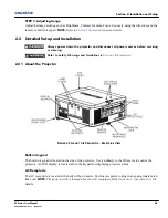
Page 19: ...icing or cleaning Refer to Safety Warnings and Guidelines in Section 5 Maintenance 2 2 1 About the Projector Built in Keypad The built in keypad is located on the side of the projector Use it similarly to the IR remote to control the projector An LCD display is located above the keypad for displaying projector status AC Receptacle The AC receptacle is located at the back of the projector Use this ...

Page 20: ...4 All option cards have LEDs to indicate their status Cooling and Air Vents There are numerous air vents located around the projector It is important these vents remain unobstructed Adequate airflow through the projector will prevent it from overheating Kensington Lock Attachment Located at the rear of the projector to the left of the AC receptacle is a Kensington lock attachment point This provid...

Page 21: ...ng and damaging the lens which could affect your displayed image 3 Motorized lenses should not be adjusted by hand without first setting them for manual operation otherwise the zoom and focus motors may be damaged Set in Menu Configuration Lens Settings Manual Zoom Focus Lens Offset The motorized lens mount allows vertical and horizontal offset of the displayed image Shutter Standard on all models...

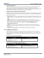
Page 22: ...light equally in all directions instead it is concentrated in a viewing cone The audience sitting within the viewing cone area will see a brighter image than those sitting just outside the area Advantages Considerations Projector is completely hidden Projector is easily accessed Usually good ambient light rejection Requires separate room or enclosure Installation cost is usually higher Advantages ...

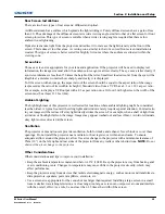
Page 23: ...creen the width of the screen must be at least 13 3 feet 4m Ambient Lighting The high brightness of this projector is well suited for locations where ambient lighting might be considered less than ideal A typical room with ceiling lights and windows rarely requires special attention Contrast ratio in your images will be reduced if stray light directly strikes the screen For example when a shaft of...

Page 24: ...e Website PN 020 100221 XX Due to lens manufacturing tolerances for lens focal length actual throw distance can vary 5 between lenses with the same nominal throw ratio Vertical and horizontal position The correct vertical and horizontal position of the projector in relation to the screen depends on the lens type and the screen size Ideally the projector should be positioned perpendicular to the sc...

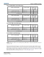
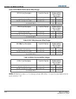
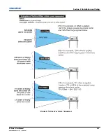
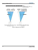
Page 25: ...ontal offset of a lens type See Figure 2 13 Horizontal Offset Examples WUXGA Lens Description Lens Part Number Minimum Offset Above or Below Lens Center Lens ILS 0 73 1SX 0 67 1HD 118 100110 XX 22 132 pixels Lens ILS 1 25 1 6SX 1 16 1 49HD 118 100111 XX 82 492 pixels ALL OTHER LENSES 112 672 pixels WXGA Lens Description Lens Part Number Minimum Offset Above or Below Lens Center Lens ILS 0 73 1SX 0...

Page 26: ...65 pixels ALL OTHER LENSES 54 518 pixels WXGA Lens Description Lens Part Number Minimum Offset Above or Below Lens Center Lens ILS 0 73SX 0 67HD 118 100110 XX 18 122 pixels Lens ILS 1 25 1 6SX 1 16 1 49HD 118 100111 XX 58 396 pixels ALL OTHER LENSES 76 518 pixels HD 1080p Lens Description Lens Part Number Minimum Offset Above or Below Lens Center Lens ILS 0 73 1SX 0 67 1HD 118 100110 XX 12 115 pix...

Page 27: ...Section 2 Installation and Setup M Series User Manual 2 13 020 100009 05 Rev 1 09 2010 FIGURE 2 12 VERTICAL OFFSET EXAMPLES ...

Page 28: ...2 14 M Series User Manual 020 100009 05 Rev 1 09 2010 Section 2 Installation and Setup FIGURE 2 13 HORIZONTAL OFFSET EXAMPLES ...

Page 29: ...nly the Christie approved ceiling mount kit designed for your projector Refer to the installation instructions and safety guidelines provided in the kit Special Mounting The projector can also be rotated front to back up to 360 degrees and fixed in a rotated position without affecting performance However the side to side tilt limit of the projector must not exceed 15 degrees to ensure optimal perf...

Page 30: ...ry such as the framing test pattern showing the cross hair centered across the image Press the TEST key on the remote keypad or use the built in keypad and press the soft key that displays Test on the LCD display 2 Course focus Do a quick preliminary focus and if available zoom adjustment with the primary lens Do not worry about consistency across the image at this point just center focus It is go...

Page 31: ...ss hair image II and III If all 3 images are in focus no further action is required If boresight is required see step 3 3 If boresight is required refer to Figure 2 18 Cross Hair Pattern to understand how the adjustment screws on the lens mount affect the corresponding cross hairs on the test pattern NOTE The capscrew Figure 2 19 may be under a plastic cap remove and retain before adjusting 4 Use ...

Page 32: ... patterns are in equal sharp focus If the boresight is acceptable see step 11 If the boresight does not appear to be converging to an acceptable level of image quality or if the lens will not focus over the correct range of throw distances then the boresight requires coarse adjustment see step 9 9 The original factory boresight can be recovered approximately by positioning the 3 setscrews see Figu...

Page 33: ...tep 2 and 3 if the second key is not pressed immediately a confirmation window will appear The second key press must be pressed within 1 second of the window appearing NOTE After powering down the Status LEDs cycle and the LCD displays the message Cooling Down until cool down is complete Web User Interface UI 1 From the Main Tab Select Power OFF NOTE A window will display for confirmation on power...

Page 34: ...mputer to either of these connectors not both and control the projector remotely by entering specific serial communication commands see Section 3 Operation COMMUNICATIONS Submenu and the Serial Command document provided in the Dealer Section of the Christie Website PN 020 100224 XX 2 Connecting RS 232 Two nine pin D sub connectors labeled RS 232 IN and RS 232 OUT on the input panel are dedicated t...

Page 35: ... To connect multiple projectors in a network with serial communication 1 Connect the controlling source to the RS 232 IN connector of the first projector in the network 2 Using another serial communication cable connect one end to the RS 232 OUT connector and the other end to the RS 232 IN connector of the next projector 3 Continue this pattern of connection with all projectors in the network NOTE...

Page 36: ...ctor has one unused port RS 232 OUT see Figure 2 25 Mixed Network Communication parameters such as baud rate must be set to match the particular controlling device before connecting as a network refer to the documentation that came with your controlling device to determine the proper baud rate See Section 3 Operation for help changing the projector baud rate To communicate to all projectors set th...

Page 37: ...es this separation for Network Routing in the Communications menu see Section 4 Web User Interface If you are using an RS 422 controller for example it will communicate only with the projector to which it is connected unless you change this setting to either RS 232 and RS 422 Joined or All Joined Communicating to all Ports To relay all messages to all ports RS 232 RS 422 and Ethernet set the Netwo...

Page 38: ...st Ethernet communications select RS 232 and RS 422 Joined only projector 1 will respond via Ethernet System Integration GPIO Connector The GPIO connector on the input panel interface Figure 2 23 Connecting RS 422 provides a method of interfacing a wide range of external I O devices Refer to Appendix B Figure B 1 GPIO Connector for complete details on pin configuration and how to program the GPIO ...

Page 39: ...r from left to right Error Lamp 1 2 Amber lamp time has expired and lamp should be replaced Flashing Red lamp has malfunctioned Power Flashing Red error has occurred Details are displayed on the status display Projector State LEDs LED State Software Upgrade in progress All The pattern will alternate between Amber Off Amber Off and Off Amber Off Amber Lamp Regeneration in progress Lamp 1 2 Flashing...

Page 40: ...luding multiples of the same card type There may be up to 2 active inputs being displayed at any time either from one card or from 2 cards These 2 inputs can be routed to outputs or to the main or PIP video image NOTE See Section 7 Specifications for more details LEDS LEDs are located on the faceplate of each input card and indicate the following Power ON Green Signal Valid Green Signal Invalid OF...

Page 41: ... accepts both standard definition SD and high definition HD serial digital interface SDI signals from 1 of 2 standard definition SD or high definition HD SDI sources Both single link HD and dual link HD signals are accepted The card has two SD HD SDI outputs each of which is loop through for its respective input There are 3 LEDs on the module faceplate PWR indicates power has been applied and the ...

Page 42: ...ssociated with one of the inputs and indicate a valid signal has been detected on that input DMXC Interface Card The DMXC card is a communication interface which allows the projector to be controlled using the standard E1 11 USITT DMX512 A protocol DMX512 A 2008 DMX 512 is a serial protocol which is used for controlling lighting staging equipment from a lighting console or similar host equipment A...

Page 43: ...ectors Wiring Requirements A distribution box or digital signal switcher may be used to feed the same video signal to all the units of the tiling array See Figure 2 29 Use of Distribution Box FIGURE 2 29 USE OF DISTRIBUTION BOX Christie loop through may be used to set up a tiling array see Figure 2 29 to Figure 2 34 The system allows wiring providing the HDCP requirement is met when HDCP is used b...

Page 44: ...2 30 M Series User Manual 020 100009 05 Rev 1 09 2010 Section 2 Installation and Setup FIGURE 2 30 1X3 WIRING SOLUTION FIGURE 2 31 2X2 WIRING SOLUTION FIGURE 2 32 2X3 LOOP THROUGH WIRING SOLUTION ...

Page 45: ...Section 2 Installation and Setup M Series User Manual 2 31 020 100009 05 Rev 1 09 2010 FIGURE 2 33 2X3 SINGLE WIRING LOOP THROUGH NO PIP IS SUPPORTED FIGURE 2 34 3X3 LOOP THROUGH WIRING SOLUTION ...

Page 46: ......

Page 47: ...t In Keypad While each of the keypads provides complete control of the projector they differ slightly in their arrangement of keys and in what functions can be accessed directly with a key press rather than requiring use of the menu system You may find one keypad more convenient than another for your specific installation and application Guide to Keypads Keep these guidelines common to both keypad...

Page 48: ...3 2 M Series User Manual 020 100009 05 Rev 1 09 2010 Section 3 Operation Remote Keypad FIGURE 3 1 REMOTE KEYPAD ...

Page 49: ...hich displays all states of the keypad controls The LCD displays status information when the projector is powering up Warm up Lamp is warming up and when the projector is cooling down Cool down Lamp is cooling down The display shows the state of the keys menu structure and menu items Overview of LED and Key States The LED color of the keys indicates that the key is in one of these states Amber a f...

Page 50: ...two seconds or press twice quickly to action the projector ON or OFF Or press and release POWER followed immediately by UP ARROW KEY ON or DOWN ARROW KEY OFF to guarantee the correct action useful if you are unsure of the present state NOTES 1 After powering down the lamp cooling fan remains on for approximately five minutes to cool the lamp 2 Avoid turning the projector back on until it has been ...

Page 51: ... enabled in the Menu Preferences menu You can choose to use a scrollable list of channels when you press CHANNEL or you may prefer to enter the desired channel number blind i e without on screen feedback See Menu Preferences later in this section Slot 1 2 3 4 Press to display the next active input on the card in the slot Input Displays all inputs in all slots both active and inactive Scroll throug...

Page 52: ...ntering numbers in a text field this button acts as 0 Help Press HELP to display context sensitive help Press HELP again to toggle the help window OFF Menu Press MENU to enter or exit the projector s menu system OSD On screen display Press OSD then the DOWN ARROW to hide the projector s menu system during use To see the menus again do one of the following Press and hold OSD for two seconds Press a...

Page 53: ...menu The PROJ check box read only shows whether or not the projector physically connected to a keypad is listening to commands from that keypad A checkmark means that connected projector is listening if there is no checkmark you are communicating with a different projector To control a specific projector with the keypad press PROJ and then enter the three digit number assigned to the projector you...

Page 54: ...ress LASER to activate the laser pointer on the remote Point the remote at the screen to highlight an area of your presentation NOTE Leave batteries in the wired remote keypad for the LASER key to work 3 2 Navigating the Menus Main Menu Most of the projector controls are accessed from within the projector s menu system There are several groups of related functions with each group selectable from t...

Page 55: ...this icon apply to the selected channel only Using Slide bars and Other Controls Most of the function menus allow you to change settings by using slide bars check boxes and pull down lists Navigating options Enter the menu option number corresponding to the setting you wish to change for example press MENU 1 3 to select Vertical Stretch in the Size and Position menu Move the highlight to the optio...

Page 56: ...return to your presentation NOTES 1 You can still adjust a direct slide bar as usual if the display is turned off see OSD or Menu Preferences menu the slide bar just won t be visible 2 A direct slide bar disappears if it is not used within five seconds Check boxes Conditions are present if its adjacent check box contains a checkmark To toggle the check box highlight and press ENTER or highlight an...

Page 57: ...able character of current text To convert a lower case letter into a capital letter position the cursor on the letter and press FUNC followed by the UP ARROW KEY To convert a capital letter into a lower case letter position the cursor on the letter and press FUNC followed by the DOWN ARROW KEY NOTE Also enter numbers directly from the keypad To convert a lower case capital letter position on the l...

Page 58: ...and applications can vary greatly you will likely want to adjust and define a wide variety of parameters such as brightness contrast size etc in order to customize and optimize the display from or for a particular source For example the display settings you choose for a VCR source may be very different from those you choose for a high resolution computer source Once you have adjusted a display par...

Page 59: ...om that source A new channel can be created automatically or it can be copied from an existing channel and then edited as necessary refer to Figure 3 14 Copy A Channel and Figure 3 15 Delete a Channel When you select a direct input SLOT 1 SLOT 2 SLOT 3 or SLOT 4 any existing channels in the projector are searched for matching input and signal parameters this only occurs if Auto Source is enabled o...

Page 60: ...isplayed with the sync polarity The remaining columns pertain to each signal type such as input number slot location a variety of icons indicating access to each channel and an abbreviated description of each signal type NOTE Use UP ARROW KEY and DOWN ARROW KEY to see the remaining channels not visible in the initial display of channels SIGNAL TYPE The channel list or the Channel Setup menu identi...

Page 61: ... activate the Select Channel Operation submenu Select Delete and press ENTER a window will appear to confirm the deletion of this channel TO DELETE MULTIPLE CHANNELS highlight any channel in the Channel Setup menu and press ENTER to go to the Select Channel Operation submenu Select Delete Unlocked Only and press ENTER to delete all unlocked channels Select Delete All Channels to delete all channel...

Page 62: ...channels SLOT 1 4 corresponding to which slot in the projector s input panel the source is connected INPUT 1 6 corresponding to which input on the selected slot the source is connected to IN MENU If checked default except for automatically defined channels with unchanged parameters this defined channel will then appear in the list available when CHANNEL key is pressed If unchecked the channel must...

Page 63: ...rtain display parameters only For example press CONTRAST to access the contrast slide bar immediately Press EXIT to return to your presentation 2 To hide direct slide bars disable the Display Slide bars check box in the Menu Preferences menu 3 To hide the entire menu system from view turn off the on screen display by pressing OSD then the DOWN ARROW KEY For a good and efficient first step in perfe...

Page 64: ...need help using any of the options and controls Changes made in the Size and Position menu are applied immediately and are saved when you exit the menu press EXIT or MENU RESIZE PRESETS NOTE The same resize presets are available to all HD and SXGA screen models However the graphics used to describe each preset in this section are of the SXGA models only Resize Presets will display an image in its ...

Page 65: ... Resize Presets pull down list Select DEFAULT for most sources factory default The image will be centered and displayed as large as possible depending on the type of source FIGURE 3 19 RESIZING DEFAULT NO RESIZING displays the image in its native resolution which may or may not match the projector s resolution For example for a source with a native resolution of 800 x 600 No Resizing in an SXGA pr...

Page 66: ...hange the aspect ratio of the display PIXEL TRACK Steady flickering or several soft vertical stripes or bands across the entire image indicates poor pixel tracking Proper pixel tracking ensures that the image quality is consistent across the screen the aspect ratio is maintained and that the pixel phase can be optimized described below Tracking determines the frequency of the pixel sampling clock ...

Page 67: ... image while adjusting V POSITION Moves the image up or down within the area of available pixels NOTE The value shown represents where the approximate center of the image lies in relation to the total number of pixels available vertically This varies widely according to the signal watch the image while adjusting KEEP ASPECT ON AUTO SETUP Ensures that auto setup for any source will maintain the inp...

Page 68: ...enu to alter your main image without affecting its size or position Changes made are applied immediately and are saved when you exit the menu press EXIT or MENU Options not available for the projector model or source are disabled and appear dim grey CONTRAST Contrast increases or decreases the perceived difference between light and dark areas of your image 0 100 For best results keep close to 50 F...

Page 69: ...and manually set a specific color space NOTE For some signals the color space function is entirely automatic and the pull down list is disabled The current color space appears in the Image Settings menu Press ENTER to select a different option Select RGB unless you are using component video Select YPbPr Video with a standard definition televised signal SDTV Select YPbPr HDTV with a high definition...

Page 70: ...ssively elevated i e where blacks appear dark grey By default the projector automatically determines the best setting according to the type of incoming video signal 0 IRE Used for DVD output with enhanced black SECAM most PAL standards and Japanese NTSC 7 5 IRE Used for most NTSC video signals For some types of video you can override the setting The control is disabled for other types of video and...

Page 71: ...wever image processing controls such as Detail Sharpness Noise Reduction and Adaptive Contrast only happen on the left side or top image Changing inputs channels or test patterns will disable this control PIP operation must be disabled prior to enabling this control NOTE Split screen cannot be used in conjunction with either PIP or Tiling Both PIP and Tiling must be disabled prior to enabling Spli...

Page 72: ...re an experienced user and you have an unusual source that you feel needs further color temperature and or input level adjustment This compensates for incoming out of range drives white and black levels black that would cause crushing of light and dark colors in the image After entering a checkmark wait for the six slide bar values to stabilize then delete the checkmark and exit The Auto Input Lev...

Page 73: ...ed areas while adjusting individual black levels and input drives until both black and white edges are just visible and distinguished from neighboring pixels Images from this source will then display correct blacks and whites without crushing See Figure 3 29 Adjusting Input Levels Using the Peak Detector RED EXAMPLE SHOWN 1 Display a 16 level greyscale test pattern from the desired external source...

Page 74: ...ame signal is detected This is the Gamma control On the other hand the system also provides a global Gamma Correction control The global control offers an offset applied to all channels This offset is used to compensate for changes in ambient conditions such as ambient light in the room and projected material GAMMA CORRECTION Applies a global offset to all gamma settings for each channel It affect...

Page 75: ... of the image Setting detail above the halfway point can introduce noise in the image Lower settings can improve a noisy signal This command does not take effect unless the minimum change required in the Detail Threshold control is reached TEXTURE ENHANCEMENT Applies texture detail enhancement based on adaptive horizontal vertical and diagonal large edge and small edge enhancement processes DETAIL...

Page 76: ...blue are unchanged and reflect the native colors of the projector SD Video and HD Video Sets the output color to a specific standard value Adjusts the colors red green blue and white User Select 1 of 4 user defined sets of color adjustments defined in the Configuration menu DYNAMIC IRIS The Dynamic Iris adjusts the aperture to allow more or less light through This will allow for deeper blacks in d...

Page 77: ...tail in those bright objects will be lost It is often best to adjust the sensitivity and white compression together to find the optimal settings OPEN SPEED The open speed of the Dynamic Iris represents the maximum Dynamic Iris change per frame Increasing this value will allow the Dynamic Iris to travel further in a frame Decreasing this value will allow for a more gradual change A slower value wil...

Page 78: ...ppear black for a short duration while the system locks onto the new input SET FRAME DELAY This control delays the output signal timing relative to the input signal timing by a fraction of a frame and up to several frames The minimum latency can vary based on the amount of scaling applied to the image When using keystone or warping an additional latency is required depending on the amount of warp ...

Page 79: ...damage to the motors CALIBRATE The lens calibration procedure is needed each time a new lens is installed in order for the ILS feature to perform reliably This procedure calibrates horizontal vertical focus and zoom offset movements LOCK ALL LENS MOTORS Select this check box to prevent all lens motors from moving It will disable the Zoom Focus Horizontal and Vertical Position settings effectively ...

Page 80: ... interval the projector will automatically enter power Standby mode LAMP REGENERATION START TIME For 24 7 operation the lamp regeneration cycle is required or lamp life will be reduced This control allows you to set the time of day in 24 hour format when the regeneration cycle will start In Dual Lamp mode the cycle will be performed on each lamp separately The second lamp will wait for the first l...

Page 81: ...commended during setup or testing of the projector Or select Serial Ports to receive messages via RS 232 or RS 422 serial communication only To hide error message displays such as during shows and presentations select Off or Serial Ports SPLASH SCREEN SETUP Choose when to display a special introductory splash screen image such as your company logo graphic or message Always Off A splash screen neve...

Page 82: ...n below Numerical identity for projectors enables you to communicate with a single projector within a multiple projector application see also PROJ key in 3 1 Using the Remote Keypad or Built In Keypad If you make a mistake in assigning or changing the projector number press EXIT to cancel NOTE When multiple projectors are being used and you want to adjust the color for individual projectors to cre...

Page 83: ...the projector be changed from its default of 3002 If so enter a new valid port number here It is highly recommended not to use a port below 1000 as these ports are typically reserved for and used by common IP applications SUBNET MASK Subnet Mask determines the subnet for the IP address and must be set manually DEFAULT GATEWAY This is the IP address of the gateway used to reach any non local IP add...

Page 84: ... control of the projector but fewer devices Show Personality 18 channels This is the default setting The 18 Show channels are those controls which are expected to be used throughout the course of an actual show ie shutter channel change These channels are a subset of those in the Setup Personality Setup Personality 38 channels The 38 Setup channels are those controls which are expected to be used ...

Page 85: ... ARTNET SUBNET This is the highest level address in an ArtNet network providing expandability beyond the universe level This control specifies which ArtNet subnet group of universes the projector belongs to The Subnet applies to ArtNet only and does not apply to the DMXC input card INPUT NOISE FILTER The Input Noise Filter eliminates DMX ArtNet input oscillation which can occur on some DMX control...

Page 86: ...the Grid test pattern 3 Perform coarse keystone adjustment by using the Horizontal or Vertical Adjust setting Use the left and right arrow keys to make the adjustment NOTE The corner cursors are a guide as to how the image will be adjusted The outside edge of a cursor will be the outside edge of the image It may not be possible to exactly match the screen dimensions with the Horizontal and Vertica...

Page 87: ...ement of displays already matched for their primary colors and overall light output Use Brightness Uniformity to create an exceptionally smooth image in which no area appears brighter than another In the Brightness Uniformity menu enable the Brightness Uniformity Enable check box to access a multitude of adjustments for light output control in specific areas throughout the image Your settings appl...

Page 88: ... color temperature defined when you matched primary colors and continue to use it for all sources displayed on the wall Your other color temperatures will not necessarily be matched from screen to screen WHITE UNIFORMITY SLIDE BARS White Uniformity slide bar values may not reduce to 0 Each slide bar adjusts overall light output in a specific screen zone but the value shown represents the current s...

Page 89: ...he colors i e change their light output until all portions of the left side closely match the center color temperature Adjust an edge first focusing on its center and then adjust its corners Repeat the color adjustment of sides and corners for each edge of the screen that does not yet match the center note that each corner is adjustable in either of its two adjacent side menus When done all areas ...

Page 90: ...r disables edge blending overlap When enabled this will make the size of the Edge Blending regions obvious This control should only be used during setup What is a Blend In simple terms a blend appears as a gradient strip along an edge of a projected image It is darkest along the extreme edge of the image and lightens nearer to the rest of the image see right How Are Blends Used In multiple project...

Page 91: ...he image A setting of 50 means the midpoint is approximately 50 black for best results in most applications keep fairly close to this default Show Blending Overlap turns your defined blend width area to solid grey so that if needed simply overlapping the grey bars can seamlessly align two adjacent images Toggle the Show Blending Overlap off to reactivate the blend effect NOTE Blending Overlap appe...

Page 92: ...ht images the Blend Width may be slightly higher set according to how much overlap you have between images Use the following as a guide examples show overlapping width only values for overlapping height will differ NOTE Recommended overlap is 12 5 25 COLOR ADJUSTMENTS BY X Y SUBMENU Enter known x y coordinates from the chromaticity graph NOTES 1 For defining or changing a User 1 2 3 or 4 color per...

Page 93: ...aticity graph see Figure 3 38 CIE 1931 Chromaticity Diagram without Yellow Notch Filter Changing either or both of these numbers will change the hue of the color and relocate the triangle for possible colors For example changing the x y coordinates for red may move the color closer to orange or closer to violet which will in turn affect all displayed colors having a red component Adjust the slide ...

Page 94: ... features The use of Black Level Blending feature and the use of Christie TWIST module are mutually exclusive If Christie TWIST is installed and Black Level Blending is desired 1 Disable use of warps or 2D Keystone 2 Enable edge blending if not enabled 3 Enable Black Level Blending 4 Power down the projector then power up again Adjustments can now be made to black level controls To restore the use...

Page 95: ... the system during auto setup or initial detection of a new source Refer to 3 8 Configura tion Adjusting System Parameters and Advanced Controls GEOMETRY AND COLOR Submenu Color Adjustments by X Y for description TILING SETUP SUBMENU Image tiling allows a single input image to be displayed spread over multiple screens with each screen displaying a fraction of the image The image is displayed by th...

Page 96: ... FREEZE IMAGE Enter a check mark to freeze stop an image on a single frame Use this diagnostic tool to examine in detail a still version of an incoming image that cannot be frozen at the source For example in moving images it is sometimes difficult to observe artifacts such as external de interlacing resizing and signal noise Remove the checkmark to return to normal COLOR ENABLED Select which colo...

Page 97: ...e size and shape of different aspect ratios TEST PATTERN COLOR SWAP This function swaps the green and red color when drawing the Grid test pattern and may be helpful when adjusting convergence on the projector CALIBRATE LITELOC The LiteLoc calibration process must be run to calibrate the LiteLoc sensor on all model types Constant Intensity mode cannot operate correctly if the calibration has not b...

Page 98: ...ilable for DLV models only LAMP MODE Determines how the lamp s power and intensity are controlled If Maximum Brightness the lamp burns as brightly as possible Select Constant Intensity mode to maintain a specific brightness level over time As the lamp ages the projector will increase power as needed to closely maintain the required output from the lamp Select Constant Power to specify the power le...

Page 99: ... life in any way The default setting is 0 which means that the feature is off and no warning will be generated LAMP 1 s n and LAMP 2 s n Enter the serial number for the specified lamp This will apply the serial number to the current lamp statistics file It will not perform the archiving as done by the CHANGE LAMP function CHANGE LAMP Submenu Initiates the lamp change process for the selected lamp ...

Page 100: ...he primary or main image PIP INPUT From the list of active inputs select one to be used as the secondary or PIP SWAP MAIN PIP INPUTS Toggle the current PIP relationship so that the primary main image becomes secondary PIP and the secondary image becomes primary Swapping is available only when PIP is enabled NOTE You may experience a slight delay when swapping the Primary and Secondary images PIP E...

Page 101: ...ders PIP BORDER COLOR Choose the color of the optional border around the Picture In Picture image NOTE Disabled the boarder by setting the width to zero PIP SIZE POSITION SUBMENU Most controls in the PIP Size and Position menu adjust the PIP secondary image in the same fashion as their counterparts in the main Size and Position menu POSITION PRESETS Set the location of the PIP secondary image in t...

Page 102: ...enters standby power mode NOTE When the projector is in standby mode and Standby Active Loop Through is selected limited channel control is available inputs can be switched perform auto setup and some limited input settings can be modified 3 11 Status The read only Status menu lists a variety of details about the standard and optional components currently detected in the projector Refer to the Sta...

Page 103: ...stency in a group of projectors It ensures a good starting point for further customizing and matching however is not critical for all installations To access the Service menu password protected return to the factory set color primaries Select the Reset to Factory Defaults option in the Color Primaries submenu Then repeat the calibration process describe above and continue with matching of colors C...

Page 104: ...own in one any of the displays Use the Copy From function to copy them into a User gamut in one projector 4 In each projector select a User color adjustment 1 4 to enable Color Adjustments by X Y changes Then enter your recorded x y values into each menu 5 In each projector judge by eye and adjust x y coordinates slightly in the following manner FIGURE 3 41 JOT DOWN A SET OF MAX DRIVES X Y VALUES ...

Page 105: ...ust only as necessary to ensure that the resulting color palette is as large as possible When done you may need to adjust lamp power slightly 6 All screens should now be color matched Apply this new User gamut to a source at any time by selecting it in the Select Color Adjustment list accessed in the Advanced Image Settings menu Using the Color Saturation Menu for Color Matching To use the Color S...

Page 106: ... Virtual OSD can be accessed from here 3 14 Alarm Conditions An alarm condition consists of a message that is on the LCD display located beside the built in keypad see Section Figure 3 45 Example of Alarm Condition There are two types of alarm conditions Warning Alarm Critical Alarm A warning alarm is shown when an error or a non optimal condition has occurred That will generally not prevent the p...

Page 107: ...not affected See Figure 4 1 1 Open your web browser and type the IP address in the address bar assigned to your projector 2 Select the appropriate language from the Language drop down list located in the upper left hand corner See Figure 4 1 3 Type your username and password in the User Name and Password see Figure 4 2 fields respectively Both entries are case sensitive 4 Click the Login button Th...

Page 108: ...OTTOM OF THE MAIN WINDOW B ACTIVE INPUT WINDOW SEC TION IS READ ONLY C THESE SECTIONS PROVIDE DROP DOWN LIST SELECTIONS REFER TO SECTION 3 OPERATION FOR MORE DETAILS D PRIMARY TABS LOCATED ALONG THE TOP OF THE MAIN WINDOW E CURRENT STATUS BAR PRO VIDES INFORMATION MESSAGES ACCORDING TO THE CURRENT STATUS OF THE PROJECTOR F PROJECTOR INFORMATION SECTION IS READ ONLY G STATUS INDICATOR DISPLAYS THE ...

Page 109: ...er the Main tabbed page select the General secondary tab to view general information about Inputs Channels Projector Information Test Pattern and Color Enable see Figure 4 3 For detailed information refer to Section 3 Operation 4 3 2 Main Tabbed Page Status Under the Main tabbed page select the Status secondary tab to view the 12 Category LED status lights which indicate the projector s highest cr...

Page 110: ...VIRTUAL OSD TABBED PAGE PRESENTS THE MAIN MENU REFER TO APPENDIX A MENU TREE FOR MORE DETAILS B THE MAXIMIZE MINIMIZE BUT TON TOGGLES DEPENDING ON THE CURRENT STATE OF THE PROJEC TOR WHEN MAXIMIZED THE VIR TUAL OSD DISPLAYS OVER THE ENTIRE PAGE SO THAT SUBSE QUENT MENUS CAN BE VIEWED WITHOUT SCROLLING No access to tabbed pages when maximized C HELP BUTTON PRESENTS A POP UP WINDOW WHICH PROVIDES IN...

Page 111: ...size There are various types of menu elements Figure 4 8 and Figure 4 9 which allow you to define various projector settings These include Field entries Drop down lists Check boxes Sliders IMPORTANT When a menu option is modified through the Virtual OSD menu the projector s setting takes affect immediately ENTERING A NUMBER IN A NUMERIC FIELD 1 Position your mouse pointer within the numeric field ...

Page 112: ...ick the check box with your mouse pointer This enables or clears the option respectively CLOCK SETTING 1 Click within the field i e Lamp Regeneration Start Time option to allow access 2 Change the Hour Minute and Seconds fields double digit field entry as required 4 3 5 Admin Tabbed Page System Under the Admin tabbed page select the System secondary tab to upgrade upload backup and restore specifi...

Page 113: ...olor from the color palette and click OK The color square changes to the selected color c Click the Upload button to display the Logo Upload window Click Yes or No to confirm or cancel the upload An Upload in Progress window appears A RESTORE SECTION ALLOWS YOU TO SELECT THE FILE AND FILE TYPE THAT YOU WISH TO RESTORE B BACKUP SECTION ALLOWS YOU TO SELECT THE FILE AND FILE TYPE THAT YOU WISH TO BA...

Page 114: ... type All Preferences Configuration Channels Users or Real Time Events RTE from the Restore drop down list NOTE DO NOT select All unless transferring all files from one projector to another or cloning 4 Click Restore to initiate the restore A Restore in Progress bar appears Once finished a confirmation message appears Performing a Diagnostic Test using Interrogator 1 Click Interrogate to initiate ...

Page 115: ... user that you wish to remove from the Users window See Figure 4 13 2 Click Delete User to open the Delete User window A confirmation message appears 3 Click Yes or No to proceed or ignore the action 4 3 7 Advanced Tabbed Page RTE The RTE secondary tabbed page is where you can manage real time events i e add delete edit copy and setup the GPIO as described in the following section RTE Buttons The ...

Page 116: ...ent will run based on the projector time NOTE Synching the projector time to be that of your system time 8 Enter a description of the scheduled event in the Description field NOTE Maximum of 100 characters 9 Enter a serial command or a sequence of serial commands with which you wish the projector to perform in the Command String box If a GPIO command string is needed click the GPIO Output Helper b...

Page 117: ...ndow See Figure 4 17 RTE Listing Window Example 2 To activate or deactivate one or more RTEs listed in the RTE Listing window select or clear each check box in the Active column accordingly FIGURE 4 17 RTE LISTING WINDOW EXAMPLE TO ADD A SYSTEM EVENT 1 Click Add to open the RTE Wizard 2 Select the System Event tab 3 Select a type of event from the System Event drop down list NOTE Depending on the ...

Page 118: ...as shown in Figure 4 19 GPIO Event See Appendix B for detailed information To Add a Function Key Event 1 Click Add to open the RTE Wizard 2 Select the Function Key Event tab 3 Select a Function key from the drop down list as shown in Figure 4 20 Function Key Event Refer to Section 3 Operation for detailed information To Add a DMX Channel Event 1 Click Add to open the RTE Wizard 2 Select the DMX Ch...

Page 119: ... M Series Serial Commands Technical Reference Information P N 020 100224 xx available at the Christie Website 2 Click Send to add the serial command See Figure 4 22 4 3 8 About Tabbed Page Provides information about the projector s software version model serial number and license information NOTE The information provided on the Version and License tabs are read only FIGURE 4 22 ADD SERIAL COMMAND ...

Page 120: ......

Page 121: ...ear a radiator or heat register or within an enclosure To ensure adequate airflow around the projector with a minimum clearance of 25cm 10 on the left right and rear sides of the projector from any walls or other obstructions NOTE Do not obstruct the air exchange to the projector 5 1 2 Optional Filters Use only special high efficiency Christie approved filters This projector is not equipped with f...

Page 122: ...wn Replace Filters 1 Unscrew the 2 captive screws at the top of each filter door Figure 5 1 Allow the door to rest down away from the projector 2 Slide the filter or dust air filter if fitted out 3 Insert the new air fog filter with ensuring the white layer facing into the projector NOTE Each filter is a two stage filter the black activated charcoal layer faces out and the white layer faces the pr...

Page 123: ...t free blower 2 Fold a microfibre cloth smooth and gently wipe remaining dust particles from the lens Wipe evenly with the smooth portion of the cloth that has no folds or creases Do not apply pressure with your fingers use the tension in the folded cloth itself to collect dust 3 If significant dust is still bound to the surface dampen a clean microfibre cloth with coated optics cleaning solution ...

Page 124: ...ety regulations for your area 5 To use lamp OFF command a In the lamp menu select CHANGE LAMP This will prompt for the old lamp serial number if it was not previously entered b Enter the new lamp serial number NOTE This action is not mandatory it is recommended for accurate lamp statistics to be archived 6 Install the new lamp a Take precaution to align the new lamp properly in the correct orienta...

Page 125: ...he following The Status LEDs are cycling green The LCD displays the warning Image Processor Upgrading The LED on the Image Processor card flashes green The Web page shows a warning that the Image processor card is upgrading When this occurs the projector should not be AC power cycled and the Image Processor card should not be removed This operation may take as long as 5 minutes to complete 6 2 Lam...

Page 126: ...signals are received by the projector Pressing any key on the remote control towards the front or rear sensor the Status LED will blink regardless if any command is executed If the LED does not blink restart the projector 3 Ensure the remote keypad is enabled If the projector is powered using the built in keypad open the OSD menu and go to the Main Menu Configuration Communication submenu and chec...

Page 127: ...ould have the same subnet mask yet unique IP addresses 6 7 Displays 6 7 1 The projector is on but there is no display 1 Was a lens cover accidently left on Remove lens cover 2 On the LCD display check that the shutter is open This will also be indicated by the shutter LED being green 3 Is the correct input selected Check cable connections 4 Check if menus appear on the screen 5 Can you access test...

Page 128: ...ce 3 The source if non video may need a different sync tip clamp location 6 7 6 The Upper Portion of the Display is Waving Tearing or Jittering This can occur with video or VCR sources Check your source 6 7 7 Portions of the Display are Cut Off or Warped to the Opposite edge Resizing may need adjustment Adjust until entire image is visible and centered 6 7 8 Display Appears Compressed Vertically S...

Page 129: ...tangular 1 Check leveling of the projector Ensure the lens surface and screen are parallel to one another 2 Is the vertical offset correct Make the necessary adjustments to the vertical offset on the lens mount 6 7 14 Display is Noisy 1 Display adjustment at the input source may be required Adjust pixel tracking phase and filter Noise is particularly common on YPbPr signals from a DVD player 2 Ens...

Page 130: ...fter performing a backup of Interrogator you may be prompted from a pop up window before saving the file If you have not specifically set Internet Explorer to automatically open save the file without prompting and if pop up windows have been disabled by enabling the pop up blocker then you will not be able to save the file Disable the pop up blocker from Main Tools Pop up Blocker NOTE Different ty...

Page 131: ...Section 6 Troubleshooting M Series User Manual 6 7 020 100009 05 Rev 1 09 2010 FIGURE 6 1 ...

Page 132: ......

Page 133: ...1 Pixel Format 7 1 2 Brightness ANSI Lumens 1080p H x V square pixels 1920 x 1080 SXGA H x V square pixels 1400 x 1050 WUXGA HxV square pixels 1920 x 1200 WXGA HxV square pixels 1366 x 768 Projector Model Lamp Mode Brightness ANSI WX7K M Dual 5700 WX10K M Dual 9500 DS 6K M Dual 6300 DS 10K M Dual 10 500 Roadster DS 10K M HD6K M Dual 6000 HD10K M Dual 10 000 Roadster HD10K M WU7K M Dual 6300 HD12K ...

Page 134: ... white ANSI 13 pt w o electronic corr 15 25 Single lamp Full white ANSI 13 pt w o electronic corr 25 35 Full white ANSI 13 pt w electronic corr 5 5 Full black ANSI 13 pt Negative uniformity shall be between 35 and 0 and positive uniformity shall be between 0 and 35 Full white ANSI 13 pt 0 005 cluster on u v chart CIE 1976 Full black ANSI 13 pt 0 075 cluster on u v chart CIE 1976 ANSI 9 point measu...

Page 135: ...re sight alignment must be adjusted for zero angular error Note convergence error includes the effects of lateral color in the projection lens Measurements must be done on horizontal and vertical test pattern lines that intersect the center of the image White Default CCT without YNF 7700K 2000K 350W Lamp 8900K 2000K 200W Lamp White YNF CCT with YNF activation electronically corrected 6500K 1000K R...

Page 136: ...creen No blemishes Red 0 bright 1 dark Green 0 bright 0 dark Blue 0 bright 2 dark non adjacent Evaluate on multi burst or fine grid test pattern No visible artifacts with observer at 1 full screen height from image 1080p centering error 5 of vertical offset 32 pixels SXGA centering error 5 of vertical offset 26 pixels WUXGA centering error 5 5 of vertical offset 32 pixels WXGA centering error 5 of...

Page 137: ...sets 5 sec nominal depends on lens type Manual Lens Movement Manual over ride permissible for zoom and focus Lens type Reverse Telecentric Internal focus Motorized zoom and focus with position feedback NOTE Calculated Throw distance values are subject to a 5 lens tolerance Throw Ratio Lens Description Part Number WXGA SXGA HD WUXGA Fixed Lens ILS 0 73 1SX 0 67 1HD 118 100110 xx 0 75 0 73 0 67 0 67...

Page 138: ...Fans automatically adjust to required speed to maintain projector at proper operating range as function of outside ambient temperature Standby All fans are off when projector is in standby and not running active loop through on a Twin HDMI option card Temperature range for variable fan speed 5 to 40 degrees C Transition steps Smooth speed transitions with no abrupt audible changes Motorized Yellow...

Page 139: ...er is open Yellow shutter is closed FEATURE COMMENTS Video Format Re Sizing All video formats can be resized to fill screen either horizontally or vertically while maintaining aspect ratio Picture in Picture Seamless Switching Built in 2D keystone and geometry correction Auto scaling Auto de interlacing Edge blending Black level edge blending not available on WX models Warping Tiling support for u...

Page 140: ... dual 8 bit input paths into 10 bit processing Maximum Throughput 1920x1200 WUXGA In Out Standard Image Processor Card 60 Hz In 60 Hz Out Dual Image Processor Card 120 Hz In 120 Hz Out Connectors 5 female BNC 75 Ohm R Pr G Y B Pb H C V Color spaces signal types RGB YPbPr A D conversion 10 bits Connectors 2 independent HDMI inputs type A 2 loop out connectors type A Color spaces signal types RGB YC...

Page 141: ...bits Connectors BNC 75 Ohm Color spaces signal types Dual HD input SDI HDSDI Number of transmitters 2 IR Modulation frequency Dual frequency 38 kHz 455 kHz Wavelength peak intensity 950 nm Range Min 35 m Wired Keypad Wire connection option 3 pin XLR Max cable length 30 m XLR Connections Optional boot for remote with XLR connector built in to avoid requirement to use phono to XLR adaptor cable Numb...

Page 142: ...um Number of ports 1 Standard 10 100 Base T Connector Female RJ 45 Number of ports 1 Standard Supports mass storage device type Ethernet device type and or serial device type Connector USB type B full size Max bit rate 3 12 Mbps high speed 480 Mbps not supported Number of I O Lines 7 Connector Male 9 pin Dsub Output sink current logic low 100 mA 1V typical Power output 12 V 5 400mA maximum Key typ...

Page 143: ...1080p 739 W 541 W 370 W SXGA 1320 W 831 W 350 W SXGA 1267 W 805 W 300 W SXGA 1135 W 739 W 200 W SXGA 871 W 607 W 150 W SXGA 739 W 541 W 370 W WUXGA 1320 W 831 W 350 W WUXGA 1267 W 805 W 300 W WUXGA 1135 W 739 W 200 W WUXGA 871 W 607 W 150 W WUXGA 739 W 541 W 370 W WXGA 1320 W 831 W 350 W WXGA 1267 W 805 W 300 W WXGA 1135 W 739 W 200 W WXGA 871 W 607 W 150 W WXGA 739 W 541 W Maximum Current at 100V...

Page 144: ...typical 200W 3000 hrs typical 150W Warm up time to full output 5 minutes max Operating position 20 deg max tilt of lamp axis from horizontal Maximum product dimensions L x W x H with lens removed 561mm 22 1 x 500mm 19 7 x 247mm 9 75 Maximum shipping dimensions L x W x H 775mm 30 5 x 698 5mm 27 5 x 584mm 23 Product Alignment 2 of vertical adjustment on 2 front feet 1 of vertical adjustment on singl...

Page 145: ...r Filter Fog 118 100105 XX X X Stacking Frame 118 100107 XX X Ceiling Mount 118 100108 XX X Lens ILS 0 73 1SX 0 67 1HD 118 100110 XX X Lens ILS 1 25 1 6SX 1 16 1 49HD 118 100111 XX X Lens ILS 1 5 2 0SX 1 4 1 8HD 118 100112 XX X Lens ILS 2 0 2 8SX 1 8 2 6HD 118 100113 XX X Lens ILS 2 8 4 5SX 2 6 4 1HD 118 100114 XX X Lens ILS 4 5 7 5SX 4 1 6 9HD 118 100115 XX X Lens ILS 7 5 11 2SX 6 9 10 4HD 118 10...

Page 146: ...s product conforms to the following regulations related to product safety environmental requirements and electromagnetic compatibility EMC FCC Part 15 Subpart B Class A CISPR22 EN55022 CISPR24 EN55024 UL 60950 1 First Edition CAN CSA C22 2 No 60950 1 03 First edition IEC60950 1 2001 2002 95 EC RoHS ...

Page 147: ...M Series User Manual A 1 020 100009 05 Rev 1 09 2010 Appendix A Menu Tree A 1 M Series Menu Tree ...

Page 148: ......

Page 149: ...r 4 Intensity 5 Yellow Notch Filter 6 Single lamp switch on fail 7 Dynamic Iris 8 Warn when lamp reaches hours 9 Lamp 1 s n 10 Lamp 2 s n 11 Change Lamp 12 Lamp 1 History 13 Lamp 2 History 14 Reserved Change Lamp Change Lamp 1 Change Lamp 2 Input Old Lamp Serial Number 1 Old Lamp Serial Number 2 Continue 3 Abort Change Lamp 1 1 New lamp Serial Number 2 Change Lamp See Page A8 for Dynamic Iris PIP ...

Page 150: ... 232 OUT 3 Serial Mode RS 232 OUT 4 Serial Protocol RS 232 OUT Serial RS 422 Options 1 Baud Rate RS 422 2 Serial Flow Control RS 422 3 Serial Mode RS 422 4 Serial Protocol RS 422 Option Card Settings 1 Video Decoder Input card 2 Dual HD SDI Input Card 3 Twin HDMI Input Card 4 Analog BNC Input Card Video Decoder Input card 1 Grouped Inputs Mode 2 Connector 1 Grounding 3 Connector 2 Grounding 4 Conn...

Page 151: ...t Pattern 3 Left Blend Width 4 Right Blend Width 5 Top Blend Width 6 Bottom Blend Width 7 Lamp 8 Show Blending Overlap 9 Advanced Edge Blending 10 Full Screen Eye Motion Filter 11 Eye Motion Filter 12 Reset Edge Blending Settings See Page A8 for Lamp Black Level Blending 1 Black Blend Enable 2 Test Pattern 3 Left Blend Width 4 Right Blend Width 5 Top Blend Width 6 Bottom Blend Width 7 Center Brigh...

Page 152: ......

Page 153: ...re are 7 GPIO pins available on the 9pin D Sub GPIO connector which are configurable via RS 232 commands See Figure B 1 GPIO Connector The other two pins are reserved for ground and power see table below for pin identifica tion Table B 1 GPIO Pin The serial cable required for connecting the external device to the projector s GPIO connector must be compatible with the external device GPIO PINS PIN ...

Page 154: ...gh state is 3 3V A low state or value of 0 will be read on an input pin if the circuit attached to the pin is open A high state or value of 1 will be read on an input pin if the circuit attached to the pin is shorted to ground This corresponds to a switch closing event Example 1 Turn room lighting on when the projector is turned off Assumes a control automation unit is configured to turn the light...

Page 155: ...tails refer to 4 3 7 Advanced Tabbed Page RTE NOTE A real time event can use nested loops and delays Only statically defined commands can be executes i e PWR 0 SHU 1 You cannot use variables or other complex programming techniques Lens Control Limitiations WARNING Normal ILS control of the lens horizontal and vertical positions by the projector respects the boundaries of the lens keepout area This...

Page 156: ...esults Below is a table of how projectors should be configured assuming that all projectors are to be controlled independently and use the same personality Table C 1 Show personality Correct Example Table C 2 Setup personality Correct Example Base Channel All projectors using Show Personality Correct Base Channel All projectors using Setup Personality Correct 1 Projector 1 18 ch 1 Projector 1 38 c...

Page 157: ...ens shift disable 172 255 Lens shift enable 255 Locks all lens motors 5 Lens Zoom Coarse 0 to 255 Scaled as of total control range which is 0 to 2100 125 Locked by channel Lens shift enable 6 Lens Zoom Fine 0 7 Lens Zoom Coarse 0 to 255 Scaled as of total control range which is 0 to 2100 128 Locked by channel Lens shift enable 8 Lens Zoom Fine 0 9 Lens Lens Horizontal position Coarse 0 to 255 Scal...

Page 158: ...d Will not change power stat on default 17 Image Size 0 to 255 Scaled as of total control range which is 200 to 4000 67 18 Image Vertical Stretch 0 to 255 Scaled as of total control range which is 200 to 3000 91 19 Setup Functions Projector Orientation 0 49 Front Projection 50 99 Rear Projection 100 149 Front Projection Inverted 150 199 Rear Projection Inverted 255 Will not change projector orien ...

Page 159: ...9 Max Drivers 20 39 Color Temperatur endables 31 40 59 SD Video 60 79 HD Video 80 99 User setting 1 100 119 User setting 2 120 139 User setting 3 140 159 User setting 4 0 30 Colormetry Color Purity Filter 0 85 CPF Off 172 255 CPF On This is the global CPF control not the channel control 0 31 Colormetry Interpolated Color Temperature 0 to 255 Scaled as of total control range which is 3200 to 9300 1...

Page 160: ... 85 Black screen Picture mute ON 172 255 Live video Picture mute OFF 255 If you wish to manually control the fade to black time the brightness channel can be used to achieve the same effect 3 Lens Shutter 0 85 Shutter Closed Black Screen 172 255 Shutter Open Live Video 255 4 Lens Lens shift enable 0 85 Lens shift disable 172 255 Lens shift enable 255 Lock all lens motors 5 Lens Zoom Coarse 0 to 25...

Page 161: ...amps off cool lamps down and go to Standby mode 172 255 Power On Switch lamps on warm up mode 128 A 5 second timer will be used before executing a power state change If the slider moves out of the On Off range within the 5 seconds the timer will be can celled Will not change power state on default 17 Reserved Reserved for future expansion No Reset 18 Reserved Reserved for future expansion No Reset...

Page 162: ...n Coarse 0 to 255 Scaled as of total control range which is 0 to 2100 128 Locked by channel Lens shift enable 9 Lens Lens Horizontal position Fine 0 10 Lens Lens Vertical position Coarse 0 to 255 Scaled as of total control range which is 0 to 2100 128 Locked by channel Lens shift enable 11 Lens Lens Vertical position Fine 0 12 Input Input Projector Channel Selection 1 to 20 Projector Channel 1 to ...

Page 163: ... 39 Rear Projection Inverted On Screen Display 40 59 OSD On 50 59 OSD Off 60 69 Lens Calibrate 86 LOAD Test Pattern 100 104 Off 105 109 Grid 110 114 Grey Scale 16 115 119 White 120 124 Flat Grey 125 129 Black 130 134 Checker 135 139 13 Point 140 144 Color Bars 145 149 Aspect Ratio 150 154 Edge Blen 155 159 Boresight 171 EXECUTE Image Freeze 200 209 Freeze image 210 219 Unfreeze image 255 Lens Cali...

Page 164: ...Watt 40 340 Watt 178 Watt 50 350 Watt 185 Watt 60 360 Watt 192 Watt 70 100 370 Watt 200 Watt 86 LOAD 171 EXECUTE Lamp Mode 90 Auto select Single Lamp 95 Dual Lamp Mode Power Mode 100 Power Off Switch lamps off cool lamps down and go to Standby mode 105 Power On Switch lamps on warm up mode 255 17 Colormetry Brightness 0 to 255 Scaled as of total range which is 0 to 100 128 18 Colormetry Contrast 0...

Page 165: ...er 180 189 CPF Off 190 199 CPF On This is the global CPF control not the channel control 255 21 Colormetry Interpolated Color Temperature 0 to 255 Scaled as of total control range which is 3200 to 9300 128 Output Color control must be set to Color Temperature in DMX channel 20 22 Advanced Image Blend and Warp keystone enable Blend 0 4 Blend disable 5 9 Standard Blend enable 10 14 User Blend 1 enab...

Page 166: ...e Notes 23 Real Time Events RTE 0 9 Cancel current running RTE 10 19 Triggers RTE 1 20 29 Triggers RTE 2 30 39 Triggers RTE 3 40 49 Triggers RTE 4 50 59 Triggers RTE 5 60 69 Triggers RTE 6 70 79 Triggers RTE 7 86 LOAD 171 EXECUTE 255 24 Reserved Reserved for future expansion 0 25 Reserved Reserved for future expansion 0 ...

Page 167: ......

Page 168: ...itchener ph 519 744 8005 United Kingdom ph 44 118 977 8000 Germany ph 49 2161 664540 France ph 33 0 1 41 21 44 04 Hungary Eastern Europe ph 36 0 1 47 48 100 Singapore ph 65 6877 8737 Shanghai ph 86 21 6278 7708 Beijing ph 86 10 6561 0240 Korea ph 82 2 702 1601 Japan ph 81 3 3599 7481 Corporate offices Worldwide offices ...

Reviews: