background image

32

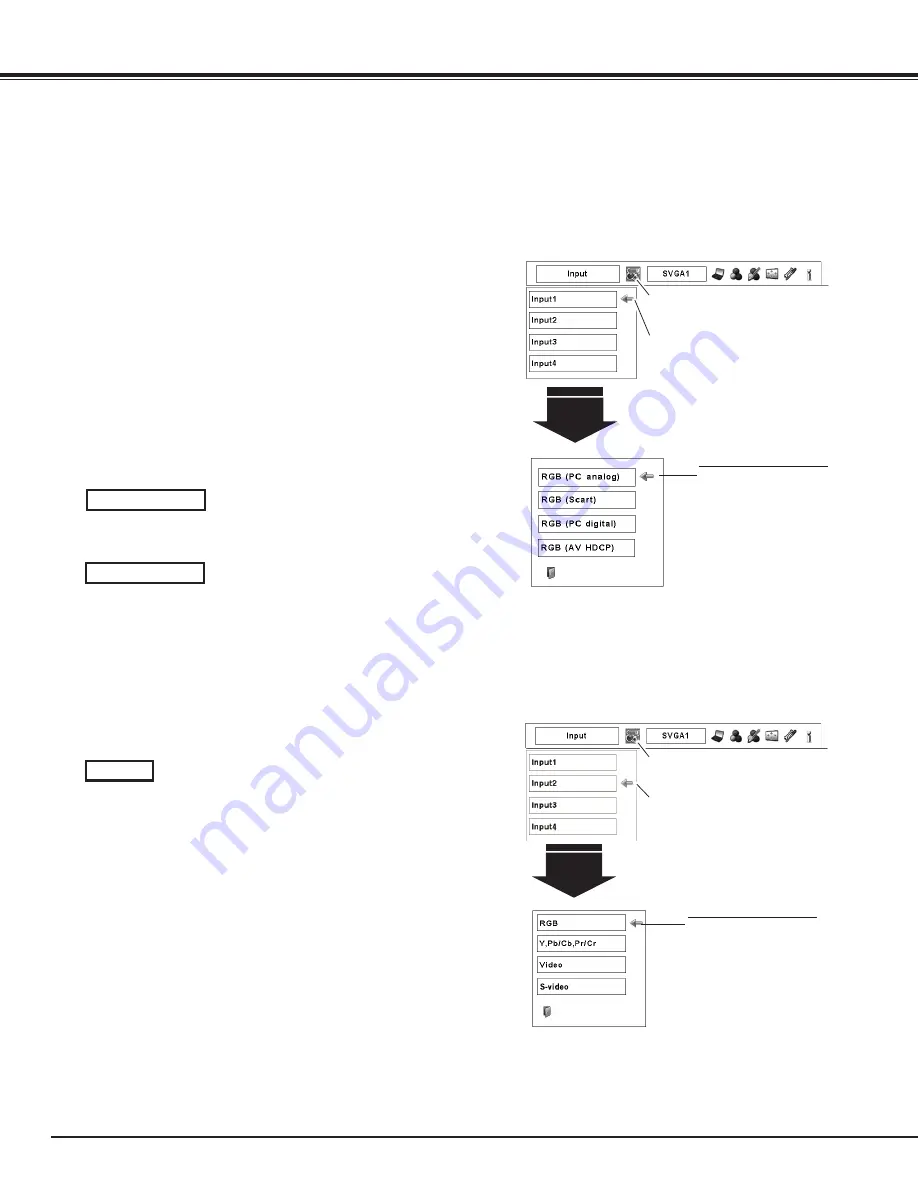
Press the MENU button to display the On-Screen Menu. 
Use the Point 

7 8

 buttons to move the red frame pointer 

to the INPUT Menu icon.

Use the Point 

ed

 buttons to move the red arrow pointer 

to the desired input and then press the SELECT button.  

Then you can switch to the desired input. 

1

2

Use the Point 

ed

 buttons to select the desired source 

and then press the SELECT button.

3

RGB (PC analog)

Menu Operation

Input Selection

Input 1

INPUT MENU

Move the pointer (red 

arrow) to the desired source 

and press the SELECT 

button.

Source Select Menu

Input Menu icon

Move the pointer (red arrow) to Input 

1 and press the SELECT button.

Computer Input Source Selection

When Selecting the INPUT 1 with DVI/D-sub 15 terminals

When your computer is connected to the INPUT 1 (ANALOG) 

terminal, select RGB (PC analog).

When your computer is connected to INPUT 1 (DIGITAL) 

terminal, select RGB (PC digital).

RGB (PC digital)

When Selecting the INPUT 2 with 5-BNC/Video/S-Video terminals

INPUT MENU

INPUT Menu icon

Move the pointer (red arrow) to Input 

2 and press the SELECT button.

Input 2

Move the pointer (red 

arrow) to RGB and press the 

SELECT button.

Source Select Menu

When your computer is connected to the INPUT 2 (5 BNC 

INPUT JACKS) terminal, select RGB.

RGB 

Note:

  • When a slot is empty, the input is displayed in grayout.

Press the select button again.  The Source Select Menu 

appears. 

4

LIT MAN USR LX900 and LW600

020-000053-02 Rev. 1 (06/08)

Summary of Contents for LW600

Page 1: ...LX900 and LW600 U S E R M A N U A L 020 000053 02...

Page 2: ......

Page 3: ...ON PRECAUCI N VORSICHT ATTENZIONE N UTILISEZ PAS LA LENTILLE EN OPTION CI DESSOUS POUR LX900 ET LW600 SINON DES DOMMAGES RISQUERAIENT DE S ENSUIVRE NO USE LA LENTE OPCIONAL A CONTINUACI N PARA LX900 Y...

Page 4: ......

Page 5: ...Projection Lens is Optional USER MANUAL 020 000053 02 LX900 and LW600 LIT MAN USR LX900 and LW600 020 000053 02 Rev 1 06 08...

Page 6: ...ear projection perpendicular omnidirectional projection variety of lens options etc Lamp Control Brightness of the projection lamp can be selected p 51 Note The On Screen Menu and figures in this manu...

Page 7: ...g Off the Projector 24 How to Operate the On Screen Menu 25 Menu Bar 26 Operating with Projector Control 27 Operating with Remote Control 29 Input Selection 31 Input 31 Computer Input Source Selection...

Page 8: ...projector is to be built into a compartment or similarly enclosed these minimum distances must be maintained Do not cover the ventilation slots on the projector Heat build up can reduce the service l...

Page 9: ...lt in a fire or electric shock Never spill liquid of any kind on the projector Do not install the projector near the ventilation duct of air conditioning equipment This projector should be operated on...

Page 10: ...air vents are provided to dissipate the heat by drawing air into the housing and the filter is located in the intake vents to prevent dust from getting inside of the projector In order to care for th...

Page 11: ...tor When not mounted properly the projector may fall causing hazards or injury For details consult your dealer The warranty on this projector does not cover any damage caused by use of any non recomme...

Page 12: ...transport service consult your dealer Do not put the projector in a case before it is cooled enough Do not transport the projector with a replacement lens installed Safety Instructions Retract the adj...

Page 13: ...e designed to provide reasonable protection against harmful interference when the equipment is operated in a commercial environment This equipment generates uses and can radiate radio frequency energy...

Page 14: ...eceiver Rear 1 Exhaust Vent t Adjustable Feet y Terminals and Connectors u Handle i Side Control o Lamp Cover 1 3 Part Names and Functions 0 4 5 t t t 1 Kensington Security Slot This slot is for a Ken...

Page 15: ...o this terminal u 5 BNC INPUT JACKS Connect the component or composite video output signal from video equipment to VIDEO Y Pb Cb and Pr Cr jacks or connect the computer output signal 5 BNC Type Green...

Page 16: ...the On Screen MENU Pan the image in DIGITAL ZOOM mode p 40 Side Control and Indicators u LENS SHIFT button Select the LENS SHIFT function p 27 0 SELECT button Used to execute the selected item It is a...

Page 17: ...flashes green in Power Management mode pp 52 72 74 Part Names and Functions r WARNING FILTER indicator Blink slow when the filter is being scrolled pp 57 72 Blink fast when the filter scroll is not w...

Page 18: ...pp 29 35 1 SHUTTER button Close the built in shutter for light blocking pp 27 30 2 SELECT button Execute the selected item Expand or compress the image in the DIGITAL ZOOM mode p 40 1 Wired Remote Jac...

Page 19: ...e control toward the projector to Infrared Remote Receivers when pressing the buttons Maximum operating range for the remote control is about 16 4 5 m and 60 degrees in front and rear of the projector...

Page 20: ...rol in the Setting Menu on page 52 1 2 Remote Control Code Part Names and Functions Check the Reset Switch to Use position in the compartment lid on the back of the remote control During holding down...

Page 21: ...allation and replacement should be made by the qualified service personnel When setting the projector after lens installation be sure to replace a Lens Cap to protect a surface When carrying or holdin...

Page 22: ...t The display position can be shifted to the left in up to 10 width of the display When the lens is shifted to rightmost The display position can be shifted to the right in up to 10 width of the displ...

Page 23: ...face board along Guide to fit Plug into Socket 3 4 INPUT OUTPUT TERMINALS Guide Socket Plug Figure shows Dual SDI terminal DVI D sub 15 Terminal 5 BNC VideoTerminal 2 TERMINAL SLOTS Factory set NOTES...

Page 24: ...tor Output Unplug the power cords of both the projector and external equipment from the AC outlet before connecting cables Cables used for connection VGA Cable D sub 15 pin DVI Cable BNC Cable BNC x 5...

Page 25: ...gital Output HDCP compatible DVI Cable SCART VGA Cable DIGITAL Unplug the power cords of both the projector and external equipment from the AC outlet before connecting cables S Video Output S VIDEO Ca...

Page 26: ...th single phase power systems having a grounded neutral conductor To reduce the risk of electrical shock do not plug into any other type of power system If you are not sure of the type of power being...

Page 27: ...e number in a column on page 80 of this manual and keep it at hand Should the PIN code be missing or forgotten consult your dealer or service center After the OK icon disappears you can operate the pr...

Page 28: ...en and then you can turn on the projector To turn off the MAIN ON OFF Switch wait until the projector is completely cooled down Power off disappears after 4 seconds Note When the On start function is...

Page 29: ...ons to adjust the values To close the On Screen Menu press the MENU button again Press the MENU button on the side control or the remote control to display the On Screen Menu Note The selected item is...

Page 30: ...r management Auto picture control Color temp White balance R G B Offset R G B Sharpness Gamma Noise reduction Progressive Reset Store pp 45 47 Used to select the system of selected video source p 41 F...

Page 31: ...ration ZOOM button FOCUS button LENS SHIFT button Operate the Auto PC Adj function The computer screen adjustment can be done easily by pressing this button See page 35 for details Auto PC Adjustment...

Page 32: ...RMATION button to display the information window on the screen To hide the information window press the INFORMATION button again or Point 7 8 buttons The information window can also be selected from t...

Page 33: ...the remote control to select the desired screen size The selected screen size mode appears on the screen for 4 seconds See pages 39 to 40 and 43 to 44 for details Press and hold the SCREEN button for...

Page 34: ...P TIMER button P Timer display Remote Control P TIMER button SHUTTER button Note See the previous page for the description of other buttons IMAGE ADJ button Press the KEYSTONE button on the remote co...

Page 35: ...l INPUT button Press the INPUT button on the side control It switches to INPUT 1 INPUT 2 INPUT 3 and INPUT 4 as you press the INPUT button Before using the INPUT button on the side control you must se...

Page 36: ...ss the SELECT button Computer Input Source Selection When Selecting the INPUT 1 with DVI D sub 15 terminals When your computer is connected to the INPUT 1 ANALOG terminal select RGB PC analog When you...

Page 37: ...cart or RGB AV HDCP and press the SELECT button Source Select Menu Input Menu icon Move the pointer red arrow to Input 1 and press the SELECT button RGB AV HDCP RGB Scart When scart video equipment is...

Page 38: ...etween your computer and the projector See Troubleshooting on page 66 Auto PC System Menu icon Selected system is displayed PC SYSTEM MENU Selecting Computer System Manually Press the MENU button to d...

Page 39: ...rtical position of certain computers cannot be fully adjusted with the Auto PC Adjustment function When the image is not provided properly with this operation manual adjustments are required pp 36 37...

Page 40: ...to adjust the number of total dots in one horizontal period to match your PC image Total dots Use the Point 7 8 buttons to adjust the horizontal picture position Position H Use the Point 7 8 buttons t...

Page 41: ...gures To store the adjusted data To clear the adjusted data To clear the adjusted data select Mode free and then press the SELECT button Move the red arrow pointer to the Mode that you want to clear a...

Page 42: ...projector Standard Picture level with improved halftone for graphics Real User preset picture adjustment in the Image Adjust Menu p 47 IMAGE 1 10 Image Level Selection Menu Operation Image Select Menu...

Page 43: ...panding the image width uniformly This function can be used to provide the squeezed video signal at 16 9 Full screen Provide the full screen image Screen Menu icon Move the red frame pointer to the de...

Page 44: ...the Main On Off Switch is pressed to Off or the AC power cord is unplugged To correct keystone distortion press the Select button The Keystone dialog box appears Use the Point ed7 8 buttons to correc...

Page 45: ...ize its performance When the Video System is 1035i or 1080i select the system manually If the projector cannot reproduce proper video image select a specific component video signal format from among 4...

Page 46: ...e red frame pointer to the desired level and press the SELECT button Image Select Menu icon Normal picture level preset on the projector Standard Picture level adjusted with fine tone Cinema User pres...

Page 47: ...t ratio Position H V Adjust the Horizontal Vertical screen position Common Save the adjusted scale to all the inputs Press the SELECT button at Common to display a confirmation box To save the scale p...

Page 48: ...int ed7 8 buttons to correct keystone distortion p 30 Ceiling Rear Ceiling When this function is set to On the picture is top bottom and left right reversed This function is used to project the image...

Page 49: ...eight 8 color management data 1 Use the Point ed buttons to move the red frame pointer to Color Management and then press the SELECT button The projected image freezes and the COLOR MANAGEMENT POINTE...

Page 50: ...mode so that you can readjust the setting for the color in that line This option is not available if the check mark is cleared Select the DEL box if you want to delete the adjusted data Press the SELE...

Page 51: ...ed green blue tone of the black level of an image from 0 to 63 Offset Red Green Blue Exit the Image Adjust Menu To store the adjusted data move the red frame pointer to the Store icon and press the SE...

Page 52: ...ust the On Screen Menu display position Press the SELECT button and the adjustment screen appears arrows appear Use the Point ed7 8 buttons to adjust the position After making the adjustment press the...

Page 53: ...decides on the starting up display from among the following options User Show the image you captured Default Show the factory set logo Off Show the countdown display only Capture Logo select Logo Not...

Page 54: ...ck on pages 53 54 Logo PIN Code Lock Enter a Logo PIN code Use the Point 7 8 buttons to switch On Off and then press the Point d button to move the pointer to Quit Press the SELECT button to close the...

Page 55: ...tched from 1 lamp mode to 2 lamps mode the image becomes brighter gradually Note When neither of the two lamps is lighted the projector will shutdown automatically When either of the two lamps does no...

Page 56: ...while the Power management function is working the Power management function is released Setting RC sensor Select a location of the infrared remote receiver of the remote control See Remote Control R...

Page 57: ...the AC power cord is connected and the Main On Off Switch is pressed to ON the projector can be operated without a PIN code Whenever you change the PIN code lock setting or the PIN code the four digi...

Page 58: ...de Setting Use the Point 7 8 buttons to adjust the Projector ID Projector ID 1 999 Factory default setting Projector ID 1 This feature allows users to set serial communication configuration Projector...

Page 59: ...ing this cooling off period When the lamp has been fully cooled down the READY indicator turns green lighting and the SHUTTER indicator keeps blinking Should the ON STAND BY button be pressed in this...

Page 60: ...3 appears on the screen When the filter scroll is counted down to 0 the Filter cartridge replacement icon Fig 4 appears on the screen and the WARNING FILTER indicator lights orange indicating that the...

Page 61: ...r the filter scroll is not working properly p 74 Fig 1 Filter replacement icon Fig 4 Filter cartridge replacement icon Fig 3 Last scroll icon Note Fig 1 Fig 2 Fig 3 or Fig 4 will not appear when the D...

Page 62: ...rtridge by holding the finger grip RECOMMENDATION We recommend avoiding dusty smoky environments when operating the projector Usage in these environments may cause a poor image quality When using the...

Page 63: ...buttons to move the red frame pointer to the Setting Menu icon Use the Point ed buttons to move the red frame pointer to Filter counter and then press the SELECT button A dialog box appears showing th...

Page 64: ...es darker or the color becomes unnatural replace lamp LAMP 1 2 REPLACE indicator lights orange LAMP 1 2 REPLACE indicator flashes orange Projection lamp is defective or fails to be turned on Restart t...

Page 65: ...MP 2 LAMP 1 CAUTION DO NOT OPERATEThe projector WHILE ANY OF LAMPS IS REMOVED IT MAY RESULT IN MALFUNCTIONS FIRE HAZARD OR OTHER ACCIDENTS NOTES ON LAMP REPLACEMENT To maintain quality of picture bett...

Page 66: ...replacing the lamp Be sure to reset the Lamp counter only after replacing the lamp Press the MENU button to display the On Screen Menu Use the Point 7 8 buttons to move the red frame pointer to the S...

Page 67: ...of hours of use as its lifetime draws to an end Risk of explosion may differ according to the environment or conditions in which the projector and lamp are being used IF A LAMP EXPLODES THE FOLLOWING...

Page 68: ...rojector Cabinet Turn off the projector press the Main On Off Switch to Off and unplug the AC power cord from the AC outlet before cleaning Gently wipe the projector body with a soft dry cleaning clot...

Page 69: ...tor to be ventilated Check the installing condition to see if the air vents of the projector are not blocked Has the projector been installed near an Air Conditioning Heating Duct or Vent Move the ins...

Page 70: ...the projection lamp Refer to page 61 PIN code dialog box appears at start up PIN code lock is being set Enter a PIN code the 1234 or numbers you have set see pages 23 53 54 The initial display is not...

Page 71: ...on on page 51 The color is strange Check the Input signal color system video system or computer system mode The image is Left Right reversed Check the Ceiling Rear function See pages 40 44 The image i...

Page 72: ...ork Check the batteries Check if the RC sensor is set properly See page 52 Make sure no obstruction is between the projector and remote control Make sure you are not too far from the projector when us...

Page 73: ...Store Gamma Progressive 0 63 0 63 0 63 0 31 0 15 Image 1 Yes No Quit Off On Noise reduction 0 63 0 63 Note The Menu display varies depending on the input signal Information Image Adjust Displayed in...

Page 74: ...the input signal Note The Menu display varies depending on the input signal SVGA 1 SVGA 2 SVGA 3 Rear Keystone Ceiling Reset Store On Off On Off Custom H V Scale Position H V On Off H V Common Reset...

Page 75: ...ote Control PIN code lock Off On1 On2 PIN code change Used time Filter counter Yes No Factory default On Countdown Off Off Display User Default Off Yes No Code 1 Remote Control Code 8 Quit Off 400H 70...

Page 76: ...s operating normally The Shutter is closed The projector is preparing for stand by or the projection lamp is being cooled down The projector cannot be turned on until cooling is completed and the READ...

Page 77: ...jector cannot be turned on until cooling is completed The lamp cannot light up The lamp has been cooled down enough and the projector is in stand by mode and ready to be turned on with the ON STAND BY...

Page 78: ...te Fig 2 Fig 3 and Fig 4 icon will not appear when the Display function is set to Off p 48 or during Freeze p 29 The filter cartridge is not installed in the projector Check the filter compartment to...

Page 79: ...900 58 200 XGA 14 1024x768 47 000 58 300 XGA 15 1024x768 58 030 72 000 MAC 19 1024x768 60 240 75 080 SXGA 1 1152x864 64 200 70 400 SXGA 2 1280x1024 62 500 58 600 SXGA 3 1280x1024 63 900 60 000 SXGA 4...

Page 80: ...8 56 160 72 000 D WXGA 5 1366x768 46 500 50 000 D WXGA 6 1280x768 47 776 59 870 D WXGA 7 1280x768 60 289 74 893 D WXGA 8 1280x768 68 633 84 837 D WXGA 9 1280x800 49 600 60 050 D WXGA 10 1280x800 41 20...

Page 81: ...nput 2 BNC Type x 5 VIDEO Y G B Pb Cb R Pr Cr H HV and V S Video Other Jacks Serial port in D sub 9 Serial port out D sub 9 USB port and Wired Remote Jack Power Voltage and Power Consumption AC 100 12...

Page 82: ...ct to change without notice LCD panels are manufactured to the highest possible standards Even though 99 99 of the pixels are effective a tiny fraction of the pixels 0 01 or less may be ineffective by...

Page 83: ...DVI 24 PIN 1 9 17 2 10 18 3 11 19 4 12 20 5 13 21 6 14 22 7 15 23 8 16 24 T M D S Data2 No Connect T M D S Data2 No Connect T M D S Data2 Shield DDC Clock DDC Data No Connect 1 5 2 4 3 6 7 8 T M D S D...

Page 84: ...et No 1 2 3 4 Factory default set No 4 3 2 1 Should the four digit number be changed the factory set number will be invalid Put the label below supplied on in a prominent place of the projector s body...

Page 85: ...18 30 7 28 185 23 62 600 200 0 234 0 26 77 680 3 03 77 9 25 235 9 25 235 29 80 757 0 5 00 127 9 63 244 5 10 53 267 5 1 14 29 9 82 249 5 10 43 265 10 89 276 5 4 72 120 8 27 210 6 89 175 Screw Holes for...

Page 86: ...nio Abad Pol gono Industrial Ventorro Del Cano Esquina C Aldea del Fresno 3 3 Puerta Izqda 28925 Alcorc n Madrid PH 34 91 633 9990 FX 34 91 633 9991 Italy Christie Authorized Reseller Angelo Tacca Via...

Reviews: