3-9
NOTICE
Systems
Bilge Pumps
The additional weight of water in the boat can adversely affect handling characteristics creating an
unsafe condition. In addition sloshing water may be corrosive to the boat’s systems.
Since water is heavy (over 8 pounds per gallon) it must not be allowed to accumulate within the vessel.
It is highly recommended there be at least one hand operated pump on the vessel in the
event of a bilge pump failure.
General Maintenance
On a regular basis you should:
1. Inspect the bilge pump intake and keep it free of dirt or material, which may impede the flow of water through
the
pump.
– To remove the pump strainer, depress the lock tabs on both sides of the pump and lift the pump motor.
2. Check the bilge pump float switch by moving it manually.
– The float switch should move freely without sticking or binding. If it doesn’t, service or replace the switch
before using the boat.
3. The bilge pump should start when the float switch is raised and should stop when lowered.
– If the pump does not start, reset the circuit breakers. If the pump still fails to start, replace the float switch
before using the boat.
– If you have to remove the float switch, verify proper operation of the new switch.
4. After inspection reinstall the unit.
Electric Bilge Pumps
It is illegal to discharge oily bilge water into the waters of the United States.
Bilge oil spills must be mopped up and the oil and rags properly disposed of.
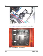
There are four (4) bilge pumps in this boat, located on the centerline in the engine compartment. One
bilge pump is located forward and three are located in the engine compartment. The RH uses the Rule
2000 GPH model. For switch location refer to
Figure 3-1
.
Three of the bilge pumps may be operated in the “manual” mode by placing the bilge pump switch,
located on the helm control panel, to the
ON
position. The indicator light on the switch illuminates
indicating the pump is energized. One bilge pump is a high-water pump and engages automatically
when the float switch is tripped and will sound an audible alarm at the helm.
Do not run a bilge pump for an extended period of time in a dry environment.
Damage and/or premature wear to the pump may result.
Summary of Contents for 2014 36 RH Corsair
Page 19: ...Introduction 36 RH Corsair B...
Page 23: ...Safety and Operations...
Page 57: ...2 36 Safety and Operations...
Page 88: ...Figure 3 26 Fluid Tank Sensor 3 30 Systems...
Page 115: ...Care and Cleaning 3 57 Systems Marine Tops And Covers Care And Cleaning...
Page 116: ...Care and Cleaning Figure 3 51 Canvas Top 3 58 Systems...
Page 118: ...Care and Cleaning 3 60 Systems Maintenance and Cleaning Of Stainless Steel...
Page 121: ...3 63 Systems Grey Water Systems Figure 3 56...
Page 126: ...Figure 3 70 Figure 3 68 3 68 Systems Figure 3 66 Figure 3 67 Figure 3 69 Cockpit Table...
Page 134: ...3 76...
Page 149: ...Coast Guard Accident Report B 2 Appendix B...
Page 150: ...Coast Guard Accident Report B 3 Appendix B...
Page 151: ...B 4 Appendix B Coast Guard Accident Report...
Page 152: ...Coast Guard Accident Report B 5 Appendix B...
Page 154: ...C 2 Appendix C SPECIAL NOTICE TO MARINERS Float Plan...
Page 155: ...Appendix C C 3 Float Plan...
Page 158: ...Navigational Aids D 3 Appendix D...
Page 159: ...Lateral Aids D 4 Appendix D...
Page 161: ...Maintenance Log Forms E 2 Appendix E...
Page 162: ...Maintenance Log Forms E 3 Appendix E...
Page 163: ...Glossary Of Boating Terminology Appendix F F 1...
Page 164: ...F 2...
Page 165: ...F 3...
Page 166: ...F 4...
Page 167: ...F 5...
Page 168: ...F 6...
Page 169: ...5 7 F 7...
Page 170: ...F 8...
Page 171: ...F 8...
Page 172: ...G 1 Figure 4 21...
Page 173: ...G 2 Figure 4 22...
Page 174: ...G 3 Figure 4 23...
Page 175: ...G 4 Figure 4 24...
Page 176: ...G 5...
Page 177: ...G 6 Figure 4 26...
Page 178: ...G 7 Figure 4 27...
Page 179: ...G 8 Figure 4 28...
Page 180: ...Figure 4 29 G 9...


