

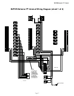
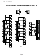


SUPER-Selector
‘
PT Control
Page 3
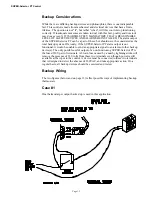
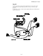
Safety Information
Caution, Warning and Danger Decals have been placed on the equipment to warn of potentially dangerous situations. Care
should be taken to keep this information intact and easy to read at all times. Replace missing or damaged safety signs.
Using the equipment for purposes other than specified in this manual may cause personal injury or damage to the equipment.
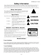
Safety–Alert Symbol
This is a safety–alert symbol. When you see this symbol on your equipment, be alert
to the potential for personal injury. Chore-Time equipment is designed to be installed
and operated as safely as possible...however, hazards do exist.
DANGER
WARNING
CAUTION
Signal Words
Signal words are used in conjunction with the safety–alert symbol to identify
the severity of the warning.
DANGER ......... indicates an imminently hazardous situation
which, if not avoided, WILL result in death
or serious injury.
WARNING ....... indicates a potentially hazardous situation
which, if not avoided, COULD result in
death or serious injury.
CAUTION ........ indicates a hazardous situation which, if not
avoided, MAY result in minor or moderate
injury.
DANGER—ELECTRICAL HAZARD
Disconnect electrical power before inspecting or servicing equipment unless
maintenance instructions specifically state otherwise.
Ground all electrical equipment for safety.
All electrical wiring must be done by a qualified electrician in accordance with
local and national electric codes.
Ground all non-current carrying metal parts to guard against electrical shock.
With the exception of motor overload protection, electrical disconnects and
over current protection are not supplied with the equipment.
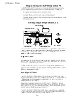
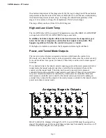
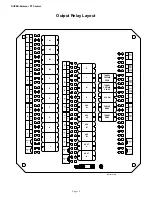
Mode Definitions
Power Ventilation
Power ventilation occurs when the tunnel curtain is closed and all ventilation is caused by fans. These fans can be
located in the side walls or the end walls. The SUPER-Selector PT will place the house in this mode of operation
whenever the temperature drops low enough to turn off the power to Tunnel Stage.
Tunnel Ventilation
Tunnel ventilation is when the tunnel air inlet curtain is opened while multiple large fans (usually 48" fans) are
running at the opposite end from the tunnel air inlet curtain. The air flow, when in tunnel mode, will be from one
end of the house to the other and the air velocity helps cool the birds. The SUPER-Selector PT will place the house
in this mode of operation when the temperature has risen to the stage that the SUPER-Selector PT is set to go from
power to tunnel. The transition to tunnel will occur when the number of fans running prior to the stage selected to
go to tunnel ventilation cannot hold the temperature below that stage’s temperature.