7
This page intentionally left blank.
Page 1: ...Control w On Delay was designed for brood applications The Proximity Intermediate Control uses a Proximity Switch to sense feed and cause the system to start and stop The Proximity Switch has sensitiv...
Page 2: ...Tube Retainer on the Inter mediate Control See Figure 2 Lift off the Tube Retainer Cradle the Feeder Tube in the Control Housing The Feeder Tube may have to be turned to allow the pan to hang straigh...
Page 3: ...ion Hopper at the end of the Feeder Line 2 3 Intermediate Control Unit Partition or Curtain Wire the Control the circuit breakers before performing any service work Important constant the black and th...
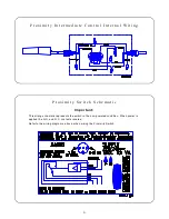
Page 4: ...g schematic represents the switch in the non powered condition When power is applied the N O and N C contacts reverse Refer to the wiring diagrams above when wiring the Proximity Switch P r o x i m i...
Page 5: ...ity The Proximity Switch is shipped with the sensitivity preset at the factory This setting is adequate for most feed types and conditions However if the sensitivity does need to be adjusted carefully...
Page 6: ...tch Box Cover 27047 10 Gasket 6777 11 Switch Box Cover 6776 12 Danger Decal 2529 480 13 Switch Box 36334 1 14 Proximity Switch Ass y 36881 1 Proximity Switch 34255 Safety Cap 36467 Liquid Tight Conn 2...
Page 7: ...7 This page intentionally left blank...
Page 8: ...Time distributor or representative for additional parts and information Chore Time Equipment A Division of CTB Inc P O Box 2000 Milford Indiana 46542 2000 U S A Phone 219 658 4101 Printed in the U S A...