background image

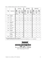
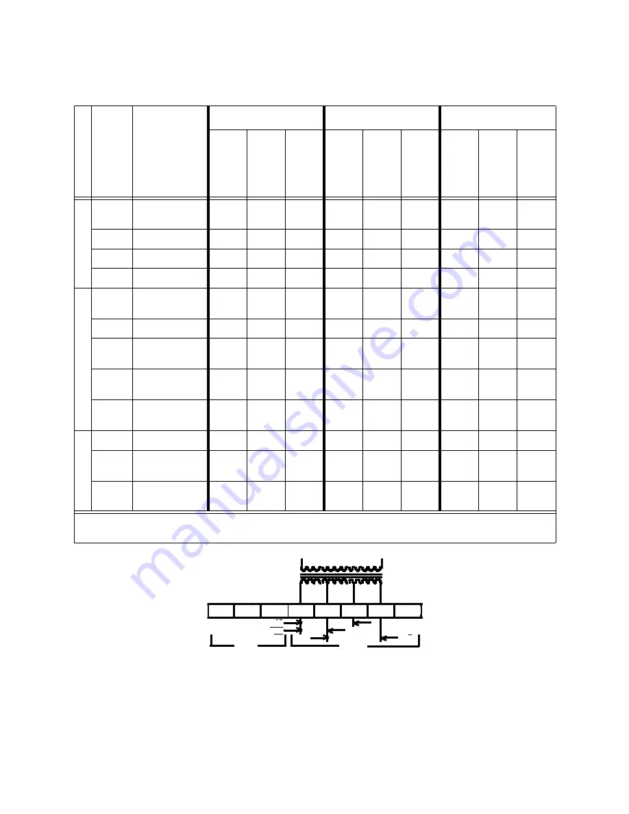
Table 7.  Minimum Requirements for E-Series UPS Installation

Term 

ID

Description

E61 (E41)

E101 (E81)

E203 (E153)

Min. 

Wire 

Gaug

(awg)

Term 

Torqu

e (in-

lbs)

Min. 

Wire 

Temp

. (°C)*

Min. 

Wire 

Gaug

(awg)

Term 

Torqu

e (in-

lbs)

Min. 

Wire 

Temp

. (°C)*

Min. 

Wire 

Gaug

(awg)

Term 

Torqu

e (in-

lbs)

Min. 

Wire 

Temp

(°C)*

GND

Chassis 
Ground

**

40

75

**

45

75

**

45

90

L1/N

Line 1

8

40

75

6

45

75

4

45

90

L2

Line 2

8

40

75

6

45

75

4

45

90

L3

Line 3

N/A

N/A

N/A

N/A

N/A

N/A

4

45

90

120A

120 V from 
Neutral

10

35

75

6

45

75

4

45

90

0

Neutral 

10

35

75

6

45

75

4

45

90

88B

208 V from 
120A

10

35

75

6

45

75

4

45

90

120B

120 V from 
Neutral

10

35

75

6

45

75

4

45

90

GND

Chassis 
Ground

opt

35

75

opt

45

75

opt

45

90

+

+240 VDC to -

N/A

N/A

N/A

4

45

75

4

45

75

-

Battery 
Common

N/A

N/A

N/A

4

45

75

4

45

75

GND

Chassis 
Ground

N/A

N/A

N/A

4

45

75

4

45

75

*  Use insulated copper wire rated 75 C minimum.
** Must be no smaller than wire connected to L1/N and L2 (for E61 and E101) or L1, L2, L3 (for E203).

GND L1/N L2 120

0

88B 120 GND

208

120

120

LINE

OUT-

X3

X4

X2

X1

Chloride Active and E-Series UPS User Manual

35

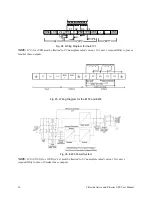
Fig. 23: Wiring Diagram for the E61

Summary of Contents for Active1000

Page 1: ...Active and E Series Uninterruptible Power Supply Operating Manual 700 VA 1000 VA 2000 VA 3000 VA 6000 VA 10000 VA 20000 VA 700 VA Rackmount 1000 VA Rackmount 2000 VA Rackmount 3000 VA Rackmount ...

Page 2: ...ty to operate the equipment This equipment was tested and complies with the limits for a Class A digital device pursuant to Part 15 of FCC Rules These limits are designed to provide reasonable protection against harmful interference when the UPS is operating in a commercial environment The UPS generates uses and can radiate radio frequency energy If installation and use is not in accordance with t...

Page 3: ... Chapter 6 Description of the Interface Active 16 Standard Interface COM A 16 Optional Interface COM B 17 Chapter 7 Maintenance Active 19 Storage 19 Cleaning 19 Chapter 8 Troubleshooting Active 20 Chapter 9 Technical Support for your Active UPS 21 Chloride Technical Support 21 Chapter 10 Active Tower and Rackmount Specifications 22 Battery Lifetime 26 Chapter 11 Chloride Introduction 27 Registerin...

Page 4: ...escription of the Interface E Series 44 Standard Interface COM A 44 Optional Interface COM B 45 Emergency Power Off EPO 46 Chapter 16 Maintenance E Series 47 Storage 47 Cleaning 47 Chapter 17 Troubleshooting E Series 48 Chapter 18 Technical Support for your E Series UPS 49 Chloride Technical Support 49 Chapter 19 E Series Specifications 50 Battery Lifetime 53 Optional Power Distribution Units PDU ...

Page 5: ... RMA number along with instructions on how to return the unit 1 3 Safety Notes WARNING Read the following information carefully Disregard of these safety notes may endanger your life and health as well as the functioning of your equipment and the safety of your data WARNING This equipment services power from more than one source The output receptacles may have voltage even when the unit is unplugg...

Page 6: ...ly remove power from output In case of interruption of the mains voltage the integrated battery maintains the power supply to the connected equipment Lay all cables so that nobody can stand on them or trip over them When connecting the device to the power supply follow the instructions in the chapter on Active Installation and Commissioning on page 11 No data transmission lines should be connected...

Page 7: ...ains failure Load in A700 A1000 A2000 A3000 OVERLOAD 105 95 105 6 min 7 min 10 min 6 min LOAD 75 95 7 min 8 min 11 min 7 min 55 75 10 min 11 min 16 min 10 min 35 55 15 min 17 min 24 min 15 min 1 35 28 min 33 min 37 min 28 min The actual battery capacity can be read from the LED battery chain see table below Battery Capacity Battery 1 35 35 55 55 75 75 95 95 100 The most reliable method for determi...

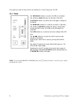
Page 8: ...me remaining when mains fail The LINE indicator is on when there is mains voltage at the UPS input The ALARM indicator is on when the UPS is faulty Simulta neously an acoustical signal is given which can be reset by pressing the BYPASS switch The switch switches the inverter off and the bypass on The UPS still has output voltage Operating the switch activates the inverter After a delay of approxim...

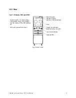
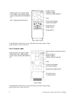
Page 9: ...d when the device is switched off and unplugged Fig 1 Active 700 Rear View Selector switch Interface COM A Interface COM B optional Connection for additional bat teries Fan Input fuse Mains input connection Output receptacles Selector switch for output voltage The selection of the output voltage must be made with the UPS switched off and unplugged Input fuse the fuse may only be changed when the d...

Page 10: ... selection of the output voltage must be made with the UPS switched off and unplugged Fig 3 Active 2000 Rear View Selector switch Interface COM A Interface COM B optional Connection for additional bat teries Fans Output Receptacle Input circuit breaker Linecord Selector Swith for output voltage The selection of the output voltage must be made with the UPS switched off and unplugged Fig 4 Active 30...

Page 11: ...n configurations battery packs are part of the unit These battery packs may only be connected electrically with the corresponding base unit 3 1 2 Further safety notes When mounting the unit into a rack it has to be attached on both sides and the front plate of the unit has to be fixed to the rack by screws There may be connected up to 2 battery packs to the Active1000 19 up to 5 battery packs to t...

Page 12: ...mage the unit and or other mounted units Fig 5 Mounting the rails at the body of the UPS or Battery Pack The following table shows the maximum configuration Table 1 Battery Cabinets UPS Type of Battery Packs Maximum Number of Packs Active700 19 None None Active1000 19 BPActive1000 19 2 units Active2000 19 BPActive3000 19 5 units Active3000 19 BPActive3000 19 5 units 3 2 3 Connection of a battery p...

Page 13: ...The following figures show the Active700 19 Active1000 19 Active2000 19 and Active 3000 19 with battery extensions NOTE No battery extension can be connected to the 700 VA unit Fig 6 Active700 19 Fig 7 Active1000 19 Fig 8 Battery Pack BPActive1000 19 To connect the battery pack to the unit use the separate cable supplied ...

Page 14: ... two battery connections The first battery pack is connected to the battery cables of the UPS each further extension is connected by means of the two cables Each cable is non interchangeable because the sockets are coded Fig 9 Active2000 19 Fig 10 Battery Pack BPActive3000 19 3 3 3 Active3000 19 Fig 11 Active3000 19 Fig 12 BPActive3000 19 ...

Page 15: ...the packing containers for any sign of physical damage Notify the carrier immediately if damage is present Carefully unpack the UPS Retain the packaging for reuse or disposal NOTE If damages are detected please inform the shipping agent immediately UPS includes UPS device Connection cable for the UPS input Output receptacles are on the UPS ...

Page 16: ...binets are not interchangeable Use ONLY the battery cabinet indicated above Connect the battery cabinet types BP1000 BP3000 to the UPS using the supplied cable The connection scheme is shown in the figures below Switch the circuit breaker on the battery cabinet to the ON position The UPS is now ready for operation NOTE Battery charging times may be longer when using an external battery cabinet WAR...

Page 17: ...ct the UPS with the mains The UPS is now again ready for normal operation Please note that the batteries have to be recharged before the complete emergency supply period is again available 5 2 Self Test The self test is a LED test With the UPS connected to the AC power switch has to be operated for at least 1 second Acknowledgment of the input is given by a single acoustical signal The elements of...

Page 18: ...verter the energy is taken from the mains 5 3 2 Battery Operation Inverter On Mains Failure Lights Illuminated During Power Failure Fig 15 Front Display Panel During Battery Operation Mains Failure In the event of a mains failure the inverter continues to supply the loads without interruption the energy is taken from the battery In this operation mode an acoustical signal is given in intervals of ...

Page 19: ...Operation Fig 16 Front Display Panel During Bypass Operation Overload 140 In the event of large overload 140 switch over to bypass is initiated and the inverter is blocked The energy is taken from the mains This is not a normal operating status In the event of mains failure the loads will no longer be supplied no UPS operation ...

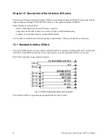
Page 20: ...nt into a network with centralized monitoring Transfer of operational states to external alarm systems The necessary communication software packages and interface cables are available as accessories 6 1 Standard Interface COM A The 9 pin SUB D connector pin contacts contains the RS 232 signals 5 output signals and 1 input signal The RS232 signal RXD can also be used as input signal when the sequen...

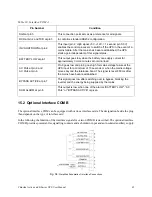
Page 21: ...10 seconds or when the mains voltage moves beyond the tolerance band The signal is reset 850 ms after the mains have been reestablished BYPASS ACTIVE at pin 7 This signal goes low after switching over to bypass blocking the inverter and the energy being supplied by the mains SUM ALARM at pin 8 This output is low when one of the alarms BATTERY LOW AC FAIL or BYPASS ACTIVE is given Chloride Active a...

Page 22: ...been reestablished The 8 5 contact provides a mirror function opening when the mains voltage fails and closing when mains power returns LOW BATT This output provides a N O contact between pins 6 and 5 and an N C contact between pins 7 and 5 The 6 5 contact closes when the battery has been depleted to the point that it can only supply current for approximately three 3 more minutes at nominal load T...

Page 23: ...s application See Ready for Operation Check on page 13 7 1 Storage For extended storage in moderate climates the batteries should be charged for 8 hours every three months Repeat it every two months in high temperature locations 1 Connect the UPS to a grounded receptacle 2 Pull out the mains plug after 8 hours 3 Note the date of charging on the packing 7 2 Cleaning CAUTION Press the switch on the ...

Page 24: ...l Services External batteries are not connected when powered Unit will not run without batteries Confirm proper battery connection LINE Indicator is not on acoustical alarm is given in intervals Mains failure Normal UPS operation see also Operational Characteristics Active on page 13 LINE Indicator is not on although mains voltage is available acoustical alarm is given in intervals Input fuse has ...

Page 25: ...warded to a cell phone A Chloride Technical Support Representative will return your call within one half hour between 5 p m and 10 p m Central Standard Time Except for emergencies calls received between 10 p m and 7 a m will be returned during normal business hours Please check with Chloride Technical Services before attempting to repair or return any Chloride product If a Chloride unit needs repa...

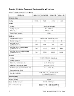
Page 26: ...d full load 10 5 15 6 18 7 10 5 Runtimes min 1 battery cabinet half load full load NA 70 30 100 30 60 30 Runtimes min 2 battery cabinets half load full load NA 130 60 200 80 120 50 Output Voltage 100 110 120 VAC single phase Voltage tolerance 3 Frequency with mains control see input frequency Frequency with internal control 50 60 Hz 0 5 Distortion factor linear non linear load max 4 max 7 Permissi...

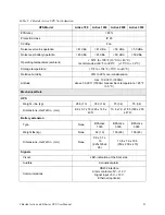
Page 27: ...max ambient temperature 95 F 35 C Mechanical Data UPS Weight lbs kg 28 6 13 35 3 16 75 34 75 34 Dimensions HxWxD in mm 8 9 x 5 7 x 16 225 x 145 x 405 13 8 x 7 9 x 18 5 350 x 200 x 470 Battery extension Type None BPActive 1000 BPActive 3000 BPActive 3000 Weight lbs kg None 42 19 106 48 106 48 Dimensions HxWxD in mm None 8 9 x 5 7 x 16 225x145x4 05 13 8 x 7 9 x 18 5 350 x 200 x 470 Signals Visual LE...

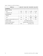
Page 28: ...antity 3 3 3 1 3 1 Type 5 15R 5 15R 5 15R L5 20R 5 15R L5 30R Maximum current at 120 VAC pf 0 7 5 8 A 8 3 A 16 7 25 A Interfaces COM A 9 pin SUB D pin contact Interfaces COM B optional Optional contact or ethernet card External battery cabinet none keyed plug 3 pole Table 5 Chloride Active UPS North America UPS Model Active 700 Active 1000 Active 2000 Active 3000 ...

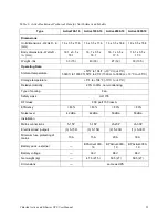
Page 29: ... ft 50 F to 95 F 1500 m to 3000 m 10 C to 35 C Storage temperature 5 F to 104 F 15 C to 40 C Relative Humidity 20 to 90 non condensing Type of cooling Fan Safety class UL1778 RFI class FCC part 15 Class A Efficiency 83 83 83 83 Noise level 42 dBa 42 dBa 50 dBa 50 dBa Installation Mains connections 5 15P 5 15P L5 20P L5 30P Electrical load output 3 5 15R 3 5 15R 2 5 20R 1 L5 30R Minimum fuse protec...

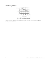
Page 30: ...Battery Lifetime 10 20 30 40 50 C 50 68 86 104 122 F 0 1 1 10 Ambient Temperature Fig 19 Typical lifetime of the batteries Figure 19 shows the typical lifetime of the batteries which are used in the UPS devices depending on the devices ambient temperature ...

Page 31: ...of your data WARNING This equipment services power from more than one source The output receptacles may have voltage even when the unit is unplugged UPSs present a different safety issue than most electrical equipment because unplugging the UPS puts it into backup mode Unplugging the UPS does not remove the electrical charge To ensure that the UPS is off push BYPASS for a minimum of 1 second befor...

Page 32: ...y follow the instructions in the chapter on E Series Installation and Commissioning on page 33 No data transmission lines should be connected or disconnected during a thunderstorm Make sure that no objects e g pins necklaces paper clips etc get inside the device In emergencies e g damaged case controls or power cables penetration of liquids or foreign matter put the device into BYPASS disconnect t...

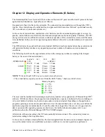
Page 33: ... battery at the onset of the mains failure Load in E61 E101 E203 OVERLOAD 105 w BPE101 95 105 9 min 9 min 15 min LOAD 75 95 10 min 10 min 20 min 55 75 13 min 13 min 25 min 35 55 21 min 21 min 45 min 1 35 40 min 40 min 90 min NOTE E Series Model E203 does not contain internal batteries The actual battery capacity can be read from the LED battery chain see table below Battery Capacity Battery 1 35 3...

Page 34: ...e state normal operation or the of battery time remaining when mains fail The LINE indicator is on when there is mains voltage at the UPS input The ALARM indicator is on when the UPS is faulty Simulta neously an acoustical signal is given which can be reset by pressing the BYPASS switch The switch switches the inverter off and the bypass on The UPS still has output voltage Operating the switch act...

Page 35: ...r switch Interface COM A Interface COM B optional Fans Output circuit breaker External battery connector Input circuit breaker Optional PDU Selector switch for output voltage The selection of the output voltage must be made with the UPS switched off E61 with optional PDU shown Fig 20 E41 or E61 ...

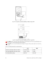
Page 36: ...Call Chloride Technical Services for information on setting output voltages 800 388 4234 or 847 990 3228 12 2 2 Selector switch must be set to 230 V EPO connection Interface COM A Interface COM B optional Fans Output circuit breaker Input circuit breaker Maintenance bypass switch Wiring box cover or optional PDU Selector switch for output voltage The selection of the output voltage must be made wi...

Page 37: ...120 3 φ for E203 6 Remove the connection plate on the back of the UPS to expose connection terminals 7 Wire input of the UPS by first connecting ground earth wire to GND ground terminal Next connect the input power leads to L1 N and L2 for E61 and E101 or L1 L2 and L3 for E203 See Table 10 Minimum Requirements for E Series UPS Installation on page 40 for minimum wire gauge wire temperature and scr...

Page 38: ...connect terminal on the UPS to the terminal on the battery cabinet Connect any additional battery cabinets in a daisy chain manner until all GND terminals terminals and terminals are connected together See Table 10 Minimum Requirements for E Series UPS Installation on page 40 for minimum wire gage wire temperature and screw torque requirements 10 Carefully replace the connection plate s on the bat...

Page 39: ...20 V from Neutral 10 35 75 6 45 75 4 45 90 0 Neutral 10 35 75 6 45 75 4 45 90 88B 208 V from 120A 10 35 75 6 45 75 4 45 90 120B 120 V from Neutral 10 35 75 6 45 75 4 45 90 GND Chassis Ground opt 35 75 opt 45 75 opt 45 90 240 VDC to N A N A N A 4 45 75 4 45 75 Battery Common N A N A N A 4 45 75 4 45 75 GND Chassis Ground N A N A N A 4 45 75 4 45 75 Use insulated copper wire rated 75 C minimum Must ...

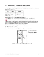
Page 40: ...r the E101 NOTE 120 A or 120B must be limited to 1 2 nameplate rated current It is user s responsibility to fuse or breaker these outputs Fig 25 Wiring Diagram for the E153 and E203 Fig 26 E203 Power System NOTE 120 A X1 X2 or 120B x2 x4 must be limited to 1 2 nameplate rated current It is user s responsibility to fuse or breaker these outputs ...

Page 41: ...ing of the UPS which means that a UPS with a higher power rating has to be used An overload alarm signal 1 signal per second is heard NOTE The UPS devices may be commissioned even without being supplied by the grid The batteries however should be charged sufficiently see above 13 3 Starting Up the E Series NOTE IF YOUR UPS WAS PURCHASED WITH A FACTORY START UP SERVICE CONTACT CHLORIDE TECHNICAL SE...

Page 42: ...are properly connected to the unit and any battery breakers are ON The LINE and BYPASS indicators and the LOAD output load indicator are illuminated After a few seconds the INVERTER indicator illuminates and the BYPASS indicator turns off The UPS is now in ON LINE operation NOTE If the LOAD output load indicator is beyond 100 then too many devices are connected to the UPS If only one device is con...

Page 43: ...FF position CAUTION Battery cabinets are not interchangeable Use ONLY the battery cabinet indicated above Connect the battery cabinet types BP1000 BP3000 and BPE61 to the UPS using the supplied cable The connection scheme is shown in the figures below With type BPE101 make the hard wired connection between UPS and the battery cabinet see figures 28 and 29 on page 40 Switch the circuit breaker on t...

Page 44: ...inet may only be done by qualified personnel in accordance with the applicable safety regulations CAUTION For the electrical installation the maximum load capacity of the connection cable has to be taken into account Table 9 Technical data of the connection cable E101 E203 Minimum permissible cable cross section 6 mm2 8 AWG 4 AWG Maximum permissible cable cross section 20 mm2 4 AWG 4 AWG Nominal o...

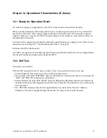
Page 45: ...nnect the UPS with the mains The UPS is now again ready for normal operation Please note that the batteries have to be recharged before the complete emergency supply period is again available 14 2 Self Test The self test is a LED test With the UPS connected to the AC power switch has to be operated for at least 1 second Acknowledgment of the input is given by a single acoustical signal The element...

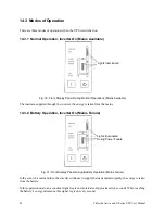
Page 46: ...h the inverter the energy is taken from the mains 14 3 2 Battery Operation Inverter On Mains Failure Lights Illuminated During Power Failure Fig 31 Front Display Panel During Battery Operation Mains Failure In the event of a mains failure the inverter continues to supply the loads uninterruptedly the energy is taken from the battery In this operation mode an acoustical signal is given in intervals...

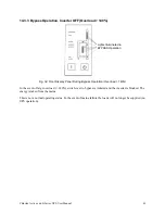
Page 47: ...Operation Fig 32 Front Display Panel During Bypass Operation Overload 140 In the event of large overload 140 switch over to bypass is initiated and the inverter is blocked The energy is taken from the mains This is not a normal operating status In the event of mains failure the loads will no longer be supplied no UPS operation ...

Page 48: ...ient into a network with centralized monitoring Transfer of operational states to external alarm systems The necessary communication software packages and interface cables are available as accessories 15 1 Standard Interface COM A The 9 pin SUB D connector pin contacts contains the RS 232 signals 5 output signals and 1 input signal The RS232 signal RXD can also be used as input signal when the seq...

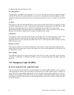
Page 49: ...or a minimum of 10 seconds or when the mains voltage moves beyond the tolerance band The signal is reset 850 ms after the mains have been reestablished BYPASS ACTIVE at pin 7 This signal goes low after switching over to bypass blocking the inverter and the energy being supplied by the mains SUM ALARM at pin 8 This output is low when one of the alarms BATTERY LOW AC FAIL or BYPASS ACTIVE is given C...

Page 50: ...een depleted to the point that it can only supply current for approximately three 3 more minutes at nominal load The 7 5 contact provides a mirror function opening when the battery is low BYPASS ACTIVE This output provides an N O contact between pins 1 and 5 The 1 5 contact closes after switching to the bypass mode In the bypass mode energy to the output of the UPS is being supplied by the mains p...

Page 51: ...s 1 Install the hard wire connections according to chapter 13 E Series Installation and Commissioning on page 33 at an appropriate source Switch on the input circuit breaker at the rear of the device for hard wired connection 2 Switch off the input circuit breaker of the UPS Then remove the connections of the UPS in an inverted sequence to what is described in chapter 13 E Series Installation and ...

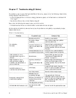
Page 52: ...sts then call Technical Services External batteries are not connected when powered Unit will not run without batteries Confirm proper battery connection LINE Indicator is not on acoustical alarm is given in intervals Mains failure Normal UPS operation see also Operational Characteristics E Series on page 41 LINE Indicator is not on although mains voltage is available acoustical alarm is given in i...

Page 53: ...act Chloride Technical Services Phone 800 388 4234 or 847 990 3229 email usa service chloridepower com Please check with Chloride Technical Services before attempting to repair or return any Chloride product If a Chloride unit needs repair or replacement Chloride Technical Services issues a Return Material Authorization RMA number along with instructions on how to return the unit ...

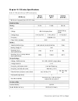
Page 54: ...ry Integrated battery type Lead calcium maintenance free None Battery voltage V 240 Runtimes min half load full load 25 8 30 12 N A Runtimes min 1 battery cabinet half load full load 94 38 100 40 40 15 Output Voltage Voltage North American 120 208 240 VAC single phase Voltage tolerance 3 Frequency with mains control see input frequency Frequency with internal control 50 60 Hz 0 5 Distortion factor...

Page 55: ...on condensing Altitude max 10 000 ft 3 000m above 5 000 ft 1 500m max ambient temperature 95 F 35 C Mechanical Data UPS Weight lbs 347 580 787 Dimensions HxWxD in mm 27 8 x 10 6 x 22 5 705 x 270 x 570 38 x 13 4 x 25 965 x 340 x 670 46 5 x 16 5 x 31 5 1180 x 420 x 800 Battery extension Type BPE61 BPE101 Weight lbs 337 894 Dimensions HxWxD in mm 27 8 x 10 6 x 22 5 705 x 270 x 570 38 x 15 x 26 4 965 ...

Page 56: ...wired min 10 AWG 6 mm2 max 6 AWG 16 mm2 hardwired min 6 AWG 10 mm2 max 4 AWG 20 mm2 hardwired 4 AWG 20 mm2 Connections continued Interfaces COM A 9 pin SUB D pin contacts Interfaces COM B optional 9 pin SUB D outlet External battery cabinet keyed plug 3 pole hardwired Min 8 AWG 6 mm2 Max 4 AWG 20 mm2 hardwired 4 AWG 20 mm2 EPO N A N A hardwired removable terminal block Table 12 Chloride E Series U...

Page 57: ...re Fig 35 Typical lifetime of the batteries Figure 19 shows the typical lifetime of the batteries which are used in the UPS devices depending on the devices ambient temperature 19 2 Optional Power Distribution Units PDU available 4 10 kVA Fig 36 Optional Power Distribution Units SPDU 2 0 SPDU 0 2 SPDU 1 0 SPDU 2 8 SPDU 2 4 SPDU 3 4 ...

Page 58: ...800 239 2257 Tel 847 990 3228 Fax 800 833 6829 Visit our website at www chlorideups com 2003 UP Systems Inc All other trademarks product and corporatate names are all property of their respected owners Specifications contained in this document are subject to change without notice UPLIT039 Rev 0 ...

Reviews: