background image

13.1 Selective protection between NM8 and NA1

13. Selectivity protection

3.45~9.45

4.14~9.45

3.45~12

4.14~12

3.45~15

4.14~15

3.45~18.75

4.14~18.75

3.45~24

4.14~24

3.45~30

4.14~30

3.45~30

4.14~30

3.45~37.7

4.14~37.7

3.45~48

4.14~48

4~60

4.14~60

4~60

4.14~60

5~75

5~75

6.3~94.5

6.3~94.5

2.5
3.0(motor)

250

2.76~9.45

3.312~9.45

2.76~12

3.312~12

2.76~15

3.312~15

2.76~18.75

3.312~18.75

2.76~24

3.312~24

2.76~30

3.312~30

2.76~30

3.312~30

2.76~37.7

3.312~37.7

3.2~48

3.312~48

4~60

4~60

4~60

4~60

5~75

5~75

6.3~94.5

6.3~94.5

2.0
2.4(motor)

200

2.208~9.45

2.65~9.45

2.208~12

2.65~12

2.208~15

2.65~15

2.208~18.75

2.65~18.75

2.208~24

2.65~24

2.208~30

2.65~30

2.208~30

2.65~30

2.5~37.7

2.65~37.7

3.2~48

3.2~48

4~60

4~60

4~60

4~60

5~75

5~75

6.3~94.5

6.3~94.5

1.6
1.92(motor)

160

1.38~9.45

1.656~9.45

1.38~12

1.656~12

1.38~15

1.656~15

1.38~18.75

1.656~18.75

1.6~24

1.656~24

2~30

2~30

2~30

2~30

2.5~37.7

2.5~37.7

3.2~48

3.2~48

4~60

4~60

4~60

4~60

5~75

5~75

6.3~94.5

6.3~94.5

1.0
1.2(motor)

100

1.725~9.45

2.07~9.45

1.725~12

2.07~12

1.725~15

2.07~15

1.725~18.75

2.07~18.75

1.725~24

2.07~24

1.725~30

2.07~30

1.725~30

2.07~30

1.725~37.7

2.07~37.7

1.725~48

2.07~48

1.725~60

2.07~60

1.725~60

2.07~60

1.725~75

2.07~75

1.725~94.5

2.07~94.5

1.25
1.5(motor)

125

1.38~9.45

1.38~12

1.38~15

1.38~18.75

1.6~24

2~30

2~30

2.5~37.7

3.2~48

4~60

4~60

5~75

6.3~94.5

1.0

100

1.656~9.45

1.656~12

1.656~15

1.656~18.75

1.656~24

2~30

2~30

2.5~37.7

3.2~48

4~60

4~60

5~75

6.3~94.5

1.20(motor)

1.104~9.45

1.325~9.45

1.104~12

1.325~12

1.104~15

1.325~15

1.25~18.75

1.325~18.75

1.6~24

1.6~24

2~30

2~30

2~30

2~30

2.5~37.7

2.5~37.7

3.2~48

3.2~48

4~60

4~60

4~60

4~60

5~75

5~75

6.3~94.5

6.3~94.5

0.80
0.96(motor)

80

0.8694~9.45

1.035~9.45

0.8694~12

1.035~12

1~15

1.035~15

1.25~18.75

1.25~18.75

1.6~24

1.6~24

2~30

2~30

2~30

2~30

2.5~37.7

2.5~37.7

3.2~48

3.2~48

4~60

4~60

4~60

4~60

5~75

5~75

6.3~94.5

6.3~94.5

0.63
0.75(motor)

63

0.69~9.45

0.828~9.45

0.8~12

0.828~12

1~15

1~15

1.25~18.75

1.25~18.75

1.6~24

1.6~24

2~30

2~30

2~30

2~30

2.5~37.7

2.5~37.7

3.2~48

3.2~48

4~60

4~60

4~60

4~60

5~75

5~75

6.3~94.5

6.3~94.5

0.50
0.60(motor)

50

0.63~9.45

0.6624~9.45

0.8~12

0.8~12

1~15

1~15

1.25~18.75

1.25~18.75

1.6~24

1.6~24

2~30

2~30

2~30

2~30

2.5~37.7

2.5~37.7

3.2~48

3.2~48

4~60

4~60

4~60

4~60

5~75

5~75

6.3~94.5

6.3~94.5

0.40
0.48(motor)

40

0.63~9.45

0.63~9.45

0.8~12

0.8~12

1~15

1~15

1.25~18.75

1.25~18.75

1.6~24

1.6~24

2~30

2~30

2~30

2~30

2.5~37.7

2.5~37.7

3.2~48

3.2~48

4~60

4~60

4~60

4~60

5~75

5~75

6.3~94.5

6.3~94.5

0.32
0.38(motor)

32

0.63~9.45

0.63~9.45

0.8~12

0.8~12

1~15

1~15

1.25~18.75

1.25~18.75

1.6~24

1.6~24

2~30

2~30

2~30

2~30

2.5~37.7

2.5~37.7

3.2~48

3.2~48

4~60

4~60

4~60

4~60

5~75

5~75

6.3~94.5

6.3~94.5

0.25
0.30(motor)

25

0.63~9.45

0.63~9.45

0.8~12

0.8~12

1~15

1~15

1.25~18.75

1.25~18.75

1.6~24

1.6~24

2~30

2~30

2~30

2~30

2.5~37.7

2.5~37.7

3.2~48

3.2~48

4~60

4~60

4~60

4~60

5~75

5~75

6.3~94.5

6.3~94.5

0.2
0.24(motor)

20

0.63~9.45

0.63~9.45

0.8~12

0.8~12

1~15

1~15

1.25~18.75

1.25~18.75

1.6~24

1.6~24

2~30

2~30

2~30

2~30

2.5~37.7

2.5~37.7

3.2~48

3.2~48

4~60

4~60

4~60

4~60

5~75

5~75

6.3~94.5

6.3~94.5

0.16
0.19(motor)

16

Circuit breaker    

Rated 
current (A)

Default setting ratings 
of short time-delay 8In (kA)

Setting 
range (kA)

Delayed tripping 
time (s)

Returnable time

Frame size 
rated current     

Rated 
current (A)

630

800

1000    

1250    

1600    

2000

2000

2500

3200

Instantaneous 
setting ratings (kA) 

NM8-125 
NM8S-125

NM8-250   
NM8S-250

4000

4000

5000

6300

NA1-2000X/NA1-2000XN/NA1-2000XH

NA1-3200X/NA1-3200XN

NA1-4000X

NA1-6300X/NA1-6300XN

5.04

0.63~9.45

6.4

0.8~12

8

1~15

10

16

16

20

25.6

32

32

1.25~18.75

2~30

2~30

2.5~37.7

3.2~48

4~60

4~60

40

50.4

5~75

6.3~94.5

Downstream

Upstream

0.1, 0.2, 0.3, 0.4

0.1, 0.2, 0.3, 0.4

0.06, 0.14, 0.23, 0.35

0.06, 0.14, 0.23, 0.35

12.8

1.6~24

C

NA1

Air Circuit Breaker

P-074

P-073

NA1

Air Circuit Breaker

Summary of Contents for NA1

Page 1: ...Air Circuit Breaker Leading every step reliable new height ...

Page 2: ...Air Circuit Breaker Leading every step reliable new height ...

Page 3: ......

Page 4: ...Page P 001 Page P 039 ACB Air Circuit Breaker NA8G NA1 ...

Page 5: ...bute electric energy and protect circuits and electric equipment against over load under voltage short circuit single phase earthing fault Having art oriented appearance high breaking capacity zero arcover and varities of intellectualized protection functions the breaker can be used for selective protection with accurate action no unnecessary power cut and better power supply reliability That brea...

Page 6: ...ing button Motor driven energy storage mechanism Breaking button Breaking making indicator Under voltage release Zero arcover hood Name plate Energy storage handle Secondary connecting part Making button Energy storage release indicator Fault breaking indicator reset button Breaking button Breaking Making indicator Intelligent controller NA8G Air Circuit Breaker P 002 Body structure ...

Page 7: ... Rocking handle deposit hole Guide rail Baffle push rod Side panel Press Press Energy storage Breaker off and energy storage over Breaker off and no energy storage Press Press Energy release Breaker on and energy storage over Breaker on and no energy storage Press Press Energy storage Press Press Energy release Air Circuit Breaker NA8G P 003 ...

Page 8: ...separator works well and the secondary circuit is connected Disconnected neither main circuit nor secondary circuit is connected 5 Push the breaker body in and turn the break body to the connected position 3 Place the breaker body on the guide rail 4 Move the breaker body onto the guide rail with a snap 2 Pull out the guide rail 1 Draw out socket placed horizontally NA8G Air Circuit Breaker P 004 ...

Page 9: ...it breaking capacity Icu kA Rated service short circuit breaking capacity Ics kA Rated short time withstand current Icw 1s kA Frequency of operation number of times hour Mechanical life Electrical Life fixed type kg draw out type kg fixed type draw out type 3000 1000 0 Wire to enter from the upper or lower port 22 26 5 42 5 55 320 254 324 258 351 282 352 352 1600 400 630 800 1000 1250 1600 690 415...

Page 10: ...50 460 390 470 600 670 550 590 950 80 100 110 120 130 220 170 250 260 420 2500 3200 4000 600 670 1047 260 420 656 NA8G 4000 Power loss Breaker type Rated current Draw out type Fixed type 4 2 2 Capacity reducing at different altitudes When the altitude is higher than 2000m there will appear changes in insulation property cooling performance pressure and the performance can be modified in reference ...

Page 11: ...arately 345 Connected position 391 Disconnected position Horizontal connection 95 76 310 149 7 a 78 5 2 Φ6 5 10 2 Φ6 5 145 3P 215 4P 95 210 36 275 63 35 76 76 76 12 Φ11 3P 16 Φ11 4P 35 60 25 15 N Pole 3P Central line 4P Central line 351 282 3P 352 4P 442 Connected position 488 Disconnected position 95 76 149 3P 155 4P 78 5 3P 75 5 4P 7 442 Connected position 488 Disconnected position 95 76 179 15 ...

Page 12: ...0 92 251 48 5 3P 45 5 4P 210 22 275 281 Phases barrier to be ordered separately Horizontal connection Phases barrier to be ordered separately Vertical connection N Pole 12 Φ11 3P 16 Φ11 4P 4P Central line 3P Central line 7 7 C C Note If users intend to change the horizontal connection into vertical connection they need to replace the upper and lower busbars on both sides with the same one as the c...

Page 13: ...type Size of the hole to be drilled on the panel 162 5 3P 277 5 4P 240 199 5 217 5 3P 332 5 4P Datum line 1 217 5 385 328 155 145 268 18 47 10 Φ6 376 175 97 371 162 5 Datum line 11 17 Φ14 21 5 52 Size of the hole to be drilled on the panel Datum line 2 Datum line 2 10 Datum line 1 386 7 308 258 Installation panel 10 Φ5 220 258 78 320 118 120 118 2 Breaker mounting panel From the center of the moun...

Page 14: ... connection has to be made by users themselves 115 115 115 25 12 Φ13 86 C 29 301 29 15 In A C 1600 2000 2500 20 3200 30 16 5 Datum line 25 84 112 Φ11 115 78 14 50 115 115 Datum line 29 52 445 Connected position 492 Disconnceted position 7 115 115 115 25 Φ11 14 78 55 25 57 5 52 445 Connected position 492 Disconnected position Datum line 7 Note If users want to change the vertical connection into ho...

Page 15: ...tical connection it is necessary to replace the upper and lower busbars for the N and B phases with the same one as the A and C phases N 163 5 11 200 3P 315 4P 13 200 11 246 44 7 402 Datum line 1 Datum line 2 25 90 112 100 126 14 25 Φ11 126 126 29 52 445 Connected position 492 Disconnected position Datum line 7 115 115 115 25 Φ11 14 25 35 5 52 100 57 445 Connected position 492 Disconnected positio...

Page 16: ... users want to change the horizontal connection into vertical connection they only have to additionally install vertical busbars 150 72 5 200 3P 315 4P 200 268 311 371 328 8 Φ6 4 Φ12 Datum line Datum line 12 Φ13 115 86 18 5 50 115 115 55 112 a 32 Ferrous material Datum line 115 115 115 a 100 29 Φ11 57 25 55 32 45 14 Ferrous material Datum line Note If users want to change the horizontal connection...

Page 17: ... the panel datum line 1 datum line 2 datum line 1 datum line 2 datum line 1 Size of the hole to be drilled on the panel NA8G 4000 In 2500A Draw out type only horizontal connection is provided by the factory NA8G 4000 In 2500A Draw out type vertical connection has to be made by users themselves datum line 1 Note If users want to change the horizontal connection into vertical connection they only ha...

Page 18: ...anel NA8G 4000 In 3200A 4000A Draw out type only horizontal connection is provided by the factory NA8G 4000 In 3200A 4000A Draw out type vertical connection has to be made by users themselves Note If users want to change the horizontal connection into vertical connection they only have to change the busbar of N B phases to A C phases Note If users want to change the horizontal connection into vert...

Page 19: ... on the panel NA8G 4000 In 2500A Fixed type only horizontal connection is provided by the factory NA8G 4000 In 2500A Fixed type vertical connection has to be made by users themselves Note If users want to change the horizontal connection into vertical connection they only have to rotate the busbars by 90 Note If users want to change the horizontal connection into vertical connection they only have...

Page 20: ...is provided by the factory NA8G 4000 In 3200A 4000A Fixed type vertical connection has to be made by users themselves Note If users want to change the horizontal connection into vertical connection they only have to change the busbar of N B phases to A C phases Note If users want to change the horizontal connection into vertical connection they only have to change the busbar of N B phases to A C p...

Page 21: ... be drilled on the panel Datum line 1 Datum line 1 Datum line 2 7 NA8G 6300 In 6300A Draw out type Size of the hole to be drilled on the panel 240 217 5 199 391 703 3P 97 175 162 5 2 11 17 145 155 268 328 371 18 376 47 10 Φ6 φ14 710 5 4P 595 5 3P 21 5 Datum line 1 Datum line 2 Size of the hole to be drilled on the panel Datum line 1 Datum line 1 Datum line 2 7 818 4P 308 258 Φ11 Φ11 308 258 Air Ci...

Page 22: ...112 92 30 10 5 57 125 25 Φ11 103 115 14 29 112 92 30 Note If users want to change the horizontal connection into vertical connection they only have to additionally install vertical busbars Note If users want to change the horizontal connection into vertical connection they only have to additionally install vertical busbars Note If users want to change the horizontal connection into vertical connec...

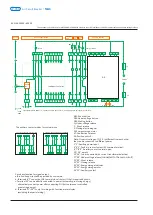
Page 23: ...QY under voltage release AX auxiliary contact XT connection terminal SAL sensitive switch FU fuse TA current transformer 1 and 2 input terminals for intellectual controller auxiliary power supply 4 5 and 6 faulty tripping contact output 5 is the common terminal AC250V 5A AX The auxiliary contact modes for customer use Ⅰ Four switch contact acquiescence Ⅱ Six switch contact Ⅲ Three open and three c...

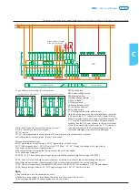
Page 24: ...ault indicator Control power Intelligent controller Breaker body Auxiliary contact available for users OFF indication ON indication Energy storage indication AC auxiliary contact for standby application Under voltage Power driven energy storage OpenClose Main circuit Intelligent controller AX The auxiliary contact modes for customer use Ⅲ Four open and four close contact Ⅳ Five open and five close...

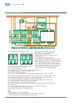
Page 25: ... auxiliary power supply 3 PE 4 5 and 6 faulty tripping contact output 5 is the common terminal AC250V 5A 7 8 and 9 auxiliary contact output 8 is the common terminal AC250V 5A 10 11 and 12 auxiliary contact output 11 is the common terminal AC250V 5A 14 and 15 RS485 communication interfaces in case of communication type 16 17 18 19 26 and 27 programmable input output points DC110V 0 5A AC250V 5A 20 ...

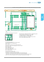
Page 26: ...14 D02 17 16 D03 PSU 1 power module PE N 14 13 15 16 17 QF TA N 5 1 2 L 12 12 DC24V 7 25 27 21 23 DC24V 13 D01 17 19 15 9 PE 11 L1 PE N 24 22 2 Green Red Profibus DP FU ST DP module 8 6 SAL 12 18 14 16 20 D14 A B C D13 D15 D16 10 Fault indicator Breaker body Intelligent controller Frame 3200 and 6300 shell controller power supply AC230V and AC400V Frame 3200 6300 shell controller power supply DC22...

Page 27: ...gether for the current multiple setting of long time delay overcurrent There are 1 2 4 8 12 16 20 24 30 s nine settings altogether for the time delay time setting of long time delay overcurrent in case of 6IR There are 1 5 2 2 5 3 4 5 6 8 10 Ir nine settings altogether for the current multiple setting of short time short time delay For the short circuit short time delay time setting there are nine...

Page 28: ...rrent protection Default interface of the standard type controller Status for parameter query setting current of long time delay Status for fault query tripping current Status for fault query tripping time Status of simulating tripping test simulating current Status of simulating tripping test simulating time Press RESET key at any status to go back to default interface Press TEST key to go to the...

Page 29: ...ault menu left arrow key when it is necessary to move leftwards or rightwards for the set interface Move the box select menu under the current menu to change the position of said box upwards and perform the setting of the parameter ADD in the parameter setup menu Exit the current menu and go to the previous menu or cancel the value of the current setup parameter Go to the next menu of the currentl...

Page 30: ...A Ia 3 Ib 5 Ic 1 15min Ia 1000A Ib 1000A Ic 998A In 0A Ia 1050A Ib 1040A Ic 1010A In 0A 1002 A A B C N 150 100 50 0 7 4 1 Structure of the measurement menu Maximum Uab 380V Ubc 380V Uca 380V Uan 220V Ubn 220V Ucn 220V Uav 380V 0 A B C EP 200kWh EQ 10kvarh ES 200kVAh EP 200kWh EQ 200kvarh EP 0kWh EQ 0kvarh Reset Voltage U FrequencyF Electric energy E Instantaneous value Current thermal capacitance ...

Page 31: ... Uab 0 0 Ubc 0 0 Uca 0 0 Uan 0 0 Ubn 0 0 Ucn 0 0 Ia 0 0 Ib 0 0 Ic 0 0 In 0 0 U V I U I Instantaneous value Required value Waveform Base form THD thd Primary menu Secondary menu Third menu P 660kW Q 0kvar S 660kVA 1 00 Perceptual PFa 1 00 PFb 1 00 PFc 1 00 Pa 220kW Qa 0kvar Sa 220kVA Pb 220kW Qb 0kvar Sb 220kVA Pc 220kW Qc 0kvar Sc 220kVA P 660kW Q 0kvar S 660kVA P 661kW Q 2kvar S 662kVA Reset Four...

Page 32: ...ng pattern Long time delay Setting of the measurement meter Current protection Test lock Test tripping Remote locking Parameter locking 3Φ4W 4CT Wire to enter from the upper port Test type Test parameter Test initiation Remote locking Parameter locking input user password 0000 3 9 6K DO1 regional interlocking DO1 N O pulse 360s I O state DO1 DO2 DO3 DI1 1 1 1 1 three section protection I 9999A sta...

Page 33: ... mode Unloading value 1 Unloading time 1 Unloading value 2 Unloading time 2 Under voltage Over voltage U unbalanced Ground protection Grounding alarm Leakage protection Electric leakage alarm Short time delay Operating current Delay time e g 10000A 10 0In e g 200 e g 800A e g 0 4s e g 6 0 e g 600A e g 0 1s e g 100A e g 0 1s e g 8 0A e g 0 75s e g 5 0A e g 0 1s e g 4 0A e g 0 1s e g Alarm e g 200V ...

Page 34: ...ntaneous earthing earthing corresponds to vector sum T type 2 Parameter setup fixed value setting position setting function 3 Current measurement 4 Test function 5 Fault recording function 6 Self diagnostic function 7 MCR make break function 8 Human machine interface 33 22 LED Primary menu Secondary menu Third menu Fourth menu Fifth menu 1 Quadruple over current protection for long time delay shor...

Page 35: ...h current grounding protection 9 Leakage protection 10 Load monitoring function 11 Quadruple DO output function 12 DI input function 13 Regional interlocking function 14 Under and over voltage protection 15 Measurement of harmonic current 16 Neutral phase protection T s X In 0 1 0 2 0 3 0 4 0 6 1 2 3 4 5 6 8 10 20 30 0 05 0 8 10000 5000 1000 500 200 100 50 20 10 5 2 1 0 5 0 2 0 1 0 05 0 02 0 01 Ig...

Page 36: ...IR TR 1 2 4 8 12 16 20 24 30 s For setting insert a small slotted screwdriver to the knob groove as shown in the right drawing gently turn it to make the arrow of the knob point at the current and time set as required As shown in the figure the over current long time delay protection current setting value I 0 6In and the delay R tripping time is 2s in the condition of 6I R Explanation for paramete...

Page 37: ...t instantaneous over current protection Ii 2 3 4 6 8 10 12 15 OFF In optional The method for setting the current of short circuit instantaneous overcurrent protection is similar to that for long time delay overcurrent protection setting As shown in the figure the instantaneous overcurrent protection current setting value is 8In Explanation for parameter setting Current of single phase earthing pro...

Page 38: ...rmal operation Each time before the controller is switched on it is necessary to press the reset button in the upper position of the controller panel so that the breaker can be switched on again for operation b Explanation for fault memory The controller still has the function of fault memory after reset or de energized to keep a latest historical event for post analysis Only when there is a new f...

Page 39: ...r with the padlock used for such a purpose Padlock is provided by users themselves 8 9 Doorcase They are installed on the door of the distribution cabinet room to seal it with a protection level of up to IP40 8 10 Disconnected pation locking device for the draw out For the separation position of the open frame draw out circuit breaker a lock rod can be pulled out to lock the matter and the breaker...

Page 40: ...ion by rocking with it locked in the connected position Check the contract status of the secondary circuit and shoot the trouble if any 1 Check the motor control power supply and see if it is well providing power and the voltage must be 85 Us 2 Check the status of the motor energy storage mechanism 1 Check the power voltage of the closing electromagnet and it must be higher than or equal to 85 Us ...

Page 41: ...reaker fails to open 1 There may be short circuit current when the matter is switched on and in this case you shall find and shoot the trouble 2 Check to see if there is any overload current in the circuit find and shoot the trouble 3 Check the setting value of the intelligent controller for reasonability and a re setting process is necessary if not reasonable 4 Press the reset button to close the...

Page 42: ...ion Front connection mixed connection connection mode to be noted Power input Basic function Optional function this function to be added as required by the user and to be matched with the controller type Three section protection against over current Neutral line or grounding fault protection Voltage measurement Test function Fault inquiry memory function Self diagnostic function Note when the prod...

Page 43: ...ements the Air Circuit Breaker NA1 includes 5 basic frame sizes as followed P 039 NA1 Air Circuit Breaker NA1 2000X NA1 2000XN NA1 2000XH 630A to 2000A NA1 3200X NA1 3200XN NA1 4000X 2000A to 4000A NA1 6300X NA1 6300XN 4000A to 6300A NA1 1000X 200A to 1000A ...

Page 44: ...itude 2000m 2 3 Pollution grade Grade 3 2 4 Air conditions At mounting site relative humidity not exceed 50 at the max temperature of 40 higher relative humidity is allowable under lower temperature RH could be 90 at 20 special measures should be taken to occurrence of dews 2 5 Note Without the intelligent controller the breaker functions as a switch disconnector No of poles 3 3 pole 4 4 pole Rate...

Page 45: ...P 041 NA1 Air Circuit Breaker 1 3 4 5 7 8 11 12 13 14 15 ...

Page 46: ...xed type Intelligent controller Operating mechanism Auxiliary contact Locking device Arcing chamber Secondary wiring terminal Wire cable mechanical interlock Connecting rod type mechanical interlock Shunt release Closing electromagnet Under voltage release Motor driven energy storage mechanism Rotary handle Mounting plate ...

Page 47: ...storage release indicator Name plate Structure for in and out Rotate out Rotate in Under voltage release Shunt release Closing electromagnet Auxiliary contact Motor driven energy storage mechanism Locking device Intelligent controller Drawer seat Mounting plate for the fixed type breaker switch disconnector Mounting plate Mounting plate Body Drawout type breaker switch disconnector ...

Page 48: ...ion voltage Ui V 800 Rated current of N pole In A 100 In Fixed disconnection time ms 23 32 Intelligent controller Standard type M Communication type H Operation performance Electric life Mechanical life Connection pattern AC 400V 6500 AC 690V 3000 Non maintenance 15 000 Maintenance 30 000 Horizontal Vertical 38 55 22 26 5 Drawout 3P 4P Fixed 3P 4P Motor operational standard configuration weight kg...

Page 49: ...rrent In A 630 800 1000 1250 1600 2000 Drawout 3P 4P Fixed 3P 4P 67 5 80 42 52 79 90 5 45 54 NA1 2000XN NA1 2000XH Rated ultimate short circuit breaking capacity Icu Rated service short circuit breaking capacity Ics AC400V AC415V AC690V AC400V AC415V AC690V AC400V AC415V AC690V AC400V AC415V 80 50 50 65 40 40 50 40 40 42 42 65 50 50 65 40 40 50 40 40 42 42 50 40 40 50 40 40 50 40 40 42 42 Rated sh...

Page 50: ...tandard type M Communication type H 103 130 56 5 71 72 90 5 116 55 68 AC400V 1500 AC690V 1000 3 NA1 3200XN NA1 4000X Rated ultimate short circuit breaking capacity Icu Rated service short circuit breaking capacity Ics AC400V AC415V AC690V AC400V AC415V AC690V AC400V AC415V AC690V AC400V AC415V 80 65 65 65 65 65 65 50 50 45 45 65 50 50 65 50 50 65 50 50 45 45 80 65 65 65 65 50 Rated short time with...

Page 51: ...000 Non maintenance 5000 Maintenance 10 000 Horizontal Vertical 210 233 233 Drawout 3P 4P Fixed 3P 4P Standard configuration M type intelligent controller Under voltage release Shunt release Motor driven energy storage mechanism Closeing electromagnet 210 233 NA1 6300XN Rated ultimate short circuit breaking capacity Icu Rated service short circuit breaking capacity Ics AC400V AC415V AC690V AC400V ...

Page 52: ...0 1000A 46 12 Boring dimension of doorcase Installation panel Installation hole on right side Connected position Disconnected position 3P 4P NA1 1000X Fixed type NA1 1000 3P 4P L1 246 316 L 274 344 In A 200 400 630 800 1000 A mm 32 50 50 H mm 6 8 10 N 3P 4P 3 4 6 8 6 8 N N 9 3 4 9 13 12 101 5 230 H 259 315 312 L 53 268 226 270 15 216 12 46 5 35 70 70 70 A 144 18 15 35 L1 8 Φ4 n Φ10 5 n Φ13 12 200 ...

Page 53: ...ar N pole C D C C D 15 Right outer side of insulation panel Right outer side of breaker Right outer side of insulation panel 10 97 175 391 10 14 48 4 Φ13 28 60 122 5 95 5 448 4P 353 3P 292 405 3P 500 4P 37 70 42 5 258 439 2 11 17 360 4P 265 3P 70 Φ14 175 33 Φ11 202 5 N pole 95 a 95 95 92 5 In A 630 2000 a mm 10 15 20 45 Disconnected position C Right outer side of breaker 800 1600 C Right outer sid...

Page 54: ...5 95 95 86 86 N pole N pole N pole N pole horizontal connection Default Configuration L type vertical connection horizontal connection Lengthen busbar horizontal connection shortened busbar 8 Φ4 C C C D C D 172 5 448 4P 353 3P 202 5 292 405 3P 500 4P 37 70 42 5 258 439 C 10 97 175 391 122 5 95 5 a 2 11 17 360 4P 265 3P 70 Φ14 175 33 Φ11 10 14 48 60 28 95 95 95 N pole 8 Φ13 92 5 In A 630 800 1600 2...

Page 55: ...n panel In A 2000 2500 3200 a mm 20 30 2 11 17 440 4P 325 3P 70 Φ14 175 33 Φ11 528 4P 413 3P 580 4P 465 3P 352 112 92 23 97 175 391 536 37 42 5 70 258 439 10 232 5 45 Disconnected position Right outer side of breaker Opening hole on panel horizontal connection Default Configuration L type vertical connection horizontal connection shorten busbar 32 13 Φ 120 125 125 40 100 40 17 115 100 120 125 125 ...

Page 56: ...389 150 a a 112 55 60 115 402 4 Φ12 515 4P 400 3P 150 362 269 28 5 311 405 2 50 18min 211 69 5 Zero arcing covering ferreous material Opening hole on panel Installation panel Installation hole on Right outer side of breaker Installation hole on Right outer side of breaker In A 2000 2500 3200 a mm 20 30 115 40 86 40 15 115 32 13 Φ N pole 115 115 72 115 40 86 N pole 15 16 13 Φ 40 115 115 96 32 115 1...

Page 57: ...us material Horizontal Installation hole on Right outer side of breaker Installation panel Installation hole on Right outer side of breaker 21 258 13 493 515 11 11 211 362 269 28 5 311 405 2 4 Φ12 515 150 134 40 15 12 Φ13 40 189 5 189 5 120 79 134 C 30 112 55 402 4 Φ12 150 69 5 290 202 5 8 Φ4 C C C Base point Installation panel 155 5 303 379 202 5 232 5 16 48 405 273 362 Right outer side of breake...

Page 58: ... 4P 703 3P 70 175 33 Φ11 112 92 97 175 391 30 10 798 3P 352 37 42 5 70 258 439 903 4P 843 3P 958 4P 232 5 N Pole 45 Disconnected position Right outer side of breaker Opening hole on panel C Φ14 28 15 Φ C 103 40 100 155 210 20 164 246 5 246 5 182 5 55 15 Right outer side of insulation panel Right outer side of breaker C NA1 Air Circuit Breaker P 054 11 Φ4 ...

Page 59: ...8 70 Φ14 175 33 Φ11 903 958 352 37 42 5 70 258 439 232 5 103 316 5 40 80 Right outer side of breaker Opening hole on panel 45 Disconnected position NA1 6300X NA1 6300XN In 6300A Drawout type 3P C C 323 5 140 180 260 20 24 Φ15 15 Right outer side of insulation panel Right outer side of breaker P 055 NA1 Air Circuit Breaker 11 Φ4 ...

Page 60: ... SB1 Under voltage button SB2 Shunt button SB3 Close button Q Under voltage release F Shunt release X Close electromagnet M Energy storage motor DF1 DF4 Auxiliary switch 1 2 Auxiliary power input 3 4 5 Fault trip contact output 4 common terminal contact capacity AC230V 5A 6 7 To be connected with current transformer selective 8 9 Making indicator capacity AC400V 1A 27 28 Under voltage release Conn...

Page 61: ...act capacity AC230V 5A 6 7 To be connected with current transformer N O auxiliary contact capacity AC400V 1A when no current transformer 8 9 Making indicator capacity AC400V 1A 10 11 communication output 12 13 Signal alarm of load 1 output 14 15 Signal alarm of load 2 output 16 17 Making signal output 18 19 Closing signal output 20 Communication shield ground line 21 24 Voltage signal input of pha...

Page 62: ...y switch 1 2 Auxiliary power input 3 4 5 Fault trip contact output 4 common terminal contact capacity AC230V 5A 6 7 to be connected with current transformer selective 8 9 Making indicator capacity AC400V 1A 12 26 Auxiliary contact auxiliary contact capacity AC230V 1A 27 28 Under voltage release Connected to the main circuit 29 30 Shunt release 31 32 Closing release 33 34 Energy storage indicator 3...

Page 63: ...function meter display excluding the special wiring The auxiliary contact modes for customer use Ⅱ Five pairs change over contacts Ⅰ Four pairs change over contacts Main circuit Intelligent release power 1 connect positive pole and 2 connect negative pole for direct current 110V 220V 380V _ _ Auxiliary contact Emergency break Motor driven make Motor driven break Over current release SB1 Shunt butt...

Page 64: ...he input terminal of the DC power supply module and the 1 2 connect to the output terminal of the DC power supply module or else the intelligent controller will be damaged 3 4 5 Fault trip contact output 4 common terminal 6 7 8 9 Auxiliary contact normal open 10 11 empty 12 19 The programmable output terminal The normal products without these terminals but if the customer special ordered the cost ...

Page 65: ...s necessary but the cost extra added ST power module IV power converter optional components ST201 Magnify the signal capacity of the controller optional components If the customer special ordered the cost extra added 27 28 Under voltage release Connected to the main circuit 29 30 Shunt release 31 32 Closing release 33 34 Energy storage indicator 34 35 Energy storage motor 36 51 Auxiliary contact N...

Page 66: ...er current release Emergency disconnection Motor driven close Motor driven break Auxiliary switch Intelligent release power 1 connect positive pole and 2 connect negative pole for direct current 110V 220V 380V _ _ Motor driven energy storage Under voltage time delay release The auxiliary contact modes for customer use Ⅰ Four pairs change over contacts 1 2 Auxiliary power input 3 4 5 Fault trip con...

Page 67: ...nder voltage release Connected to the main circuit 29 30 Shunt release 31 32 Closing release 33 34 Energy storage indicator 34 35 Energy storage motor 36 37 Under voltage time delay release 38 51 Auxiliary contact Note a Red colored part is to be connected by users b When the power system is three phase three wire directly connect the Un to U2 If the voltage exceeds 400V special explanation when o...

Page 68: ...to the main circuit 29 30 Shunt release 31 32 Closing release 33 34 Energy storage indicator 34 35 Energy storage motor 36 37 Under voltage time delay release 38 51 Auxiliary contact Note a Red colored part is to be connected by users b When the power system is three phase three wire directly connect the Un to U2 If the voltage exceeds 400V special explanation when ordered Intelligent controller E...

Page 69: ... the top or from the bottom without reduction in performance in order to facilitate connection when installed in a switchboard 7 1 4 Put the breaker fixed type or drawer base drawout type into the installation bracket and make it fixed directly connect the cable wire of main circuit to the bus wire of fixed type circuit breaker Alternatively put breaker body onto the slideway of drawer base Plug t...

Page 70: ...of nonmagnetic material For high currents of 2500 A and upwards the metal supports or barriers in the immediate vicinity of a conductor Metal barriers through which a conductor passes must not form a magnetic loop A non magnetic material 7 1 6 Busbar connections The busbars should be suitably adjusted to ensure the connection points are positioned on the terminals before the bolts B are inserted T...

Page 71: ...6 6 spring washer Type of screw M3 M10 M12 Application Preferred tightening torque Screws for secondary terminals Installing bolts of Air Circuit Breaker Connection terminals Preferred tightening torque for NA1 s tightening components 0 5 0 7 N m 38 55 N m 61 94 N m 7 1 7 Main circuit adopts cable connection Users should not apply too strong mechanical strength on the terminals of Air Circuit Brea...

Page 72: ...ical parameters in time or add some lubricating oil etc This breaker structure is arranged vertically and modularized composition with each functioncell separated which make the maintenance easy It has compact structure reliable operation and strong free maintenance capability Please check the technical parameters on the nameplate in accordance with the requirements of order before installation Ar...

Page 73: ...it 2 2 6 I t A s 10 NA1 2000X NA1 2000XN NA1 2000XH NA1 6300X NA1 6300XN Inm A NA1 2000X NA1 2000XN NA1 2000XH NA1 3200X NA1 3200XN NA1 4000X In A 630 5 60 2 800 6 60 2 1000 8 60 2 1250 10 60 2 Thickness mm Width mm Number Busbar 1600 12 60 2 2000 10 60 3 2000 8 100 2 2500 10 100 2 3200 10 100 4 4000 3P 10 120 4 4000 4P 4000 10 100 5 5000 10 100 7 6300 10 100 8 Note the specifications in the table...

Page 74: ...5 60 65 70 In 630A In 800A In 1000A In 1250A In 1600A In 2000A 1800 2000 2200 2400 2600 2800 3000 3200 3400 3600 3800 4000 4200 40 45 50 55 60 65 70 In 2000A In 2500A In 3200A In 4000A 3800 4000 4200 4400 4600 4800 5000 5200 5400 5600 5800 6000 6200 6400 40 45 50 55 60 65 70 In 4000A In 5000A In 6300A Ambient temperature Rated current A NA1 6300X NA1 6300XN Ambient temperature Rated current A NA1 ...

Page 75: ...250 2 1250 3 1250 1 1600 2 1600 3 1600 1 2000 2 2000 3 2000 1 2500 2 2500 1 3150 2 3150 360 360 360 455 455 455 578 578 578 722 722 722 910 910 910 1154 1154 1154 1444 1444 1444 1805 1805 1805 2310 2310 2310 2887 2887 2887 3608 3608 4550 4550 9 9 9 11 4 11 4 11 4 14 4 14 4 14 4 18 18 18 22 7 22 7 22 7 19 3 19 3 19 3 24 24 24 30 30 30 36 5 36 5 36 5 48 2 48 2 48 2 60 60 75 8 75 8 9 9 18 5 11 4 11 4...

Page 76: ...250 NA1 2000X 1250 NA1 2000X 1600 NA1 2000X 1600 NA1 2000X 1600 NA1 2000X 2000 NA1 2000X 2000 NA1 2000X 2000 NA1 3200X 2500 NA1 3200X 2500 NA1 3200X 2500 NA1 3200X 3200 NA1 3200X 3200 NA1 3200X 3200 NA1 6300X 4000 NA1 6300X 4000 NA1 6300X 5000 NA1 6300X 5000 2 5 30 9 18 5 27 5 11 4 22 7 34 1 14 4 28 8 43 2 18 36 1 54 1 22 7 44 5 67 2 19 3 38 5 57 8 24 48 1 72 1 30 60 1 90 1 36 5 73 109 5 48 2 96 3...

Page 77: ... 1 035 15 1 25 18 75 1 25 18 75 0 63 0 75 motor 63 0 69 9 45 0 828 9 45 0 8 12 0 828 12 1 15 1 15 1 25 18 75 1 25 18 75 0 50 0 60 motor 50 0 63 9 45 0 6624 9 45 0 8 12 0 8 12 1 15 1 15 1 25 18 75 1 25 18 75 0 40 0 48 motor 40 0 63 9 45 0 63 9 45 0 8 12 0 8 12 1 15 1 15 1 25 18 75 1 25 18 75 0 32 0 38 motor 32 0 63 9 45 0 63 9 45 0 8 12 0 8 12 1 15 1 15 1 25 18 75 1 25 18 75 0 25 0 30 motor 25 0 63...

Page 78: ...60 5 75 5 75 6 3 94 5 6 3 94 5 1 6 24 1 6 24 2 30 2 30 2 30 2 30 2 5 37 7 2 5 37 7 3 2 48 3 2 48 4 60 4 60 4 60 4 60 5 75 5 75 6 3 94 5 6 3 94 5 1 6 24 1 6 24 2 30 2 30 2 30 2 30 2 5 37 7 2 5 37 7 3 2 48 3 2 48 4 60 4 60 4 60 4 60 5 75 5 75 6 3 94 5 6 3 94 5 1 6 24 1 6 24 2 30 2 30 2 30 2 30 2 5 37 7 2 5 37 7 3 2 48 3 2 48 4 60 4 60 4 60 4 60 5 75 5 75 6 3 94 5 6 3 94 5 1 6 24 1 6 24 2 30 2 30 2 3...

Page 79: ...r 500 8 694 9 45 8 694 12 10 44 12 8 694 15 10 44 15 8 694 18 75 10 44 18 75 6 3 7 56 motor 630 9 66 12 11 59 12 9 66 15 11 59 15 9 66 18 75 11 59 18 75 7 0 8 4 motor 700 11 04 12 11 04 15 13 25 15 11 04 18 75 13 25 18 75 8 0 9 6 motor 800 17 25 18 75 12 5 15 0 motor 1250 NM8 630 NM8S 630 8 694 9 45 8 694 12 10 44 12 8 694 15 10 44 15 8 694 18 75 10 44 18 75 6 3 7 56 motor 630 NM8S 630 NM8 1250 NM...

Page 80: ...8 9 66 60 11 59 60 9 66 60 11 59 60 9 66 75 11 59 75 9 66 94 5 11 59 94 5 11 04 24 13 25 24 11 04 30 13 25 30 11 04 30 13 25 30 11 04 37 7 13 25 37 7 11 04 48 13 25 48 11 04 60 13 25 60 11 04 60 13 25 60 11 04 75 13 25 75 11 04 94 5 13 25 94 5 17 25 24 20 7 24 17 25 30 20 7 30 17 25 30 20 7 30 17 25 37 7 20 7 37 7 17 25 48 20 7 48 17 25 60 20 7 60 17 25 60 20 7 60 17 25 75 20 7 75 17 25 94 5 20 7 ...

Page 81: ...tting ratings 12In kA 400 630 800 1000 1250 1600 2000 2000 2500 3200 3200 4000 4000 5000 6300 4 8 7 56 9 6 12 15 19 2 24 24 30 38 4 38 4 48 48 60 75 6 348 9 45 800 6 4 0 8 12 6 348 12 9 998 12 6 348 15 9 998 15 12 696 15 6 348 18 75 9 998 18 75 12 696 18 75 15 87 18 75 Note It can satisfy the selective protection if only the short time delay setting value of the superior breaker 1 32 times more th...

Page 82: ... 48 12 696 48 15 87 48 19 837 48 25 392 48 31 74 48 31 74 48 39 675 48 6 348 60 9 998 60 12 696 60 15 87 60 19 837 60 25 392 60 31 74 60 31 74 60 39 675 60 50 784 60 50 784 60 6 348 60 9 998 60 12 696 60 15 87 60 19 837 60 25 392 60 31 74 60 31 74 60 39 675 60 50 784 60 50 784 60 6 348 75 9 998 75 12 696 75 15 87 75 19 837 75 25 392 75 31 74 75 31 74 75 39 675 75 50 784 75 50 784 75 63 48 75 63 48...

Page 83: ...or the selected parameter Check Switch to query menu IR light Overload long delay fault indication Isd light Short circuit Short delay indication Test Trip test button Ii light Instantaneous Short circuit fault indication Ig light Asymmetric earthing or neutral line fault indication Alarm light Communication light Run light Note Method of 3M 3H controller application please refer to 3M 3H controll...

Page 84: ...arm setting or query interface System setting interface current calibration frequency setting Communication setting interface of H type controller DO setting interface H type with DO function Fault record query interface Operation times and life query interface Thermal capacity query interface DO state query interface Thermal capacity data Fault record number Alarm record number Earthing A B C N p...

Page 85: ...oad pre alarm value earthing alarm threshold value and delay time can be queried or changed in setting state Tripping can be simulated by software In this state or button can be pressed to add or subtract value when SET indicating lamp is flickering Don t forget to press Enter button to save data after setting Example 1 of changing long delay time is shown below 3 times P 081 NA1 Air Circuit Break...

Page 86: ...eck button in default interface to enter into query interface Last 8 fault records last 8 alarm records breaker operation times life record and thermal capacity can be queried in query state Example4 of querying second fault record is shown below C NA1 Air Circuit Breaker P 082 Long press ...

Page 87: ...Example5 of querying first alarm record is shown below Example6 of querying breaker operation times and life record is shown below P 083 NA1 Air Circuit Breaker ...

Page 88: ... A L1 TRIP TRIP TRIP TRIP s A s KA L2 L2 RUN RUN RUN RUN Tripping state Reset button should be press to return default interface after tripping at fault Press Test button to simulate Instantaneous trip Instantaneous trip state Earthing trip state C NA1 Air Circuit Breaker P 084 ...

Page 89: ... by software 5 fault records Ten 6 alarm records Ten 7 MCR protection 8 operation times records 9 thermal capacity 10 overload pre alarm 11 communication function MODBUS protocol 12 four DO function optional 3M type 1 all functions of M type controller are included 2 HMI 128 64 LCD 3H type 1 all functions of 3M type controller are included 2 voltage measurement and protection 3 frequency measureme...

Page 90: ...rip time should be less than 100ms Operating characteristics Current Ratings Range Ii tolerance Current Time tolerance a When the intelligent controller is FrameⅠ Inm 2000A Ii shouldn t be more than 50KA b When the intelligent controller is FrameⅡ Inm 3200A 4000A Ii shouldn t be more than 65KA c When the intelligent controller is FrameⅢ Inm 6300 Ii shouldn t be more than 75KA Note 14 3 Short circu...

Page 91: ...tics of single phase earthing protection Action time s Inm 1000 2000 0 2 0 8 In OFF Inm 3200 4000 6300 500 1200 A OFF 10 0 9Ig 1 1Ig tg Returnable time In the 2tg Non tripping In the tg 0 032s or tg 1 25 Tripping a When tg is 0 1s or 0 2s time permissible error is 0 040s b When Inm is 1000A Ig should be more than 100A When Inm is 2000A Ig shouldn t be more than 1200A c When Inm is 3200A 4000A or 6...

Page 92: ...5m in 3P N T mode When lead wire of external transformer needs to be longer than 2 meters special requirement should be noted when ordering Contr oller Contr oller Type Rated control power voltage Us V NA1 1000X AC230 400 NA1 2000X NA1 2000XN NA1 2000XH NA1 3200X NA1 3200XN NA1 4000X NA1 6300X NA1 6300XN AC400 230 127 DC220 110 0 35 0 7 Us 0 85 1 1 Us 0 35Us 20VA 48VA Action voltage V Reliable mak...

Page 93: ...NA1 2000XH NA1 3200X NA1 3200XN NA1 4000X NA1 6300X NA1 6300XN Energy storage time Operation frequency 15 4 Motor driven energy storage mechanism With the function of motor driven energy storing and auto restoring energy after closing the circuit breaker the mechanism can ensure closing the circuit breaker instantly after breaking the circuit breaker Manual energy store is available Characteristic...

Page 94: ...DC110V DC220V 1 3A 0 75A 0 55A 0 27A NA1 2000X NA1 2000XN NA1 2000XH NA1 3200X NA1 3200XN NA1 4000X NA1 6300X NA1 6300XN 15 6 Doorcase Installed on the door of the distribution cubicle for sealing the distribution cubicle and making the protection class to IP40 fixed type and drawout type 15 7 Phases barrier Optional Installed between the busbars to increase the creepage distance 15 8 Transparent ...

Page 95: ...te Before pulling out the key the break pushbutton should be pressed first rotate the key anticlockwise then pull it out 15 11 Cable mechanical interlock It can realize the interlock of two horizontal or vertical installed three poles or four poles drawout type or fixed type circuit breaker a If need bend the cable make sure the radian is more than 120 b Check and make sure enough lubricating oil ...

Page 96: ... circuit breakers realize the interlock between one breaker with another two different state breakers 1QF 2QF 1QF 0 0 2QF 0 1 1 0 Circuit diagram Available running manner Manner 1 three power supplies are provided for one circuit breaker only 0 9m max 52 60 52 60 40 175 190 40 175 190 50 50 C NA1 Air Circuit Breaker P 092 ...

Page 97: ... air should be always kept clean and dry There is no corrosive gas The temperature is in between 5 40 The humidity should conform to Specification 1 3 Operating Conditions c Requirement for extreme atmosphere conditions Confirming to IEC60947 2 Requirement for general environmental conditions Severe environment Low temperature 5 40 or high temperature 40 65 or humidity 90 Places with more dust and...

Page 98: ...be first done after overhaul and long time 7days of deenergization and before energization again 16 2 3 Operating characteristic inspection All accessories shall be connected with corresponding rated voltage according to the face shield nameplate requirement and the following operations should be done Electric charging closing and opening operation 5times in cycle Manual charging closing and openi...

Page 99: ...X as an example Evenly apply 7012 low temperature lubricating grease or lubricate same using the similar solid grease onto the mechanism rotating positions 16 2 4 3 Intelligent controller taking NA1 2000 type M type controller as an example Parameter setting should conform to the site use requirement 1 Press the Set button to enter the parameter setting interface Pro 2 Press the Enter button to en...

Page 100: ... to normal state 16 2 4 4 Drawer set inspection conduct the test after removing the body taking NA1 2000X as an example There are no foreign objects inside Observe whether there are foreign objects inside the draw out socket like screws wire leads scrap iron please clear same if any NA1 Air Circuit Breaker P 096 ...

Page 101: ... oxidized If any replace same Connected Disconnected Rotate the friction positions and apply oil evenly Evenly apply 7012 low temperature lubricating grease or similar solid grease onto the positions indicated in the left figure 16 2 4 5 Arcing Chamber taking NA1 2000X 6300X as an example Each arc and arcing chambers are not broken If any please promptly replace same and clear inside dust corrosio...

Page 102: ...dary circuitand drawerset secondary circuit themultimeter using At the Test or Connection position the contacts are in good contact and the connecting screws are fastened and the conductor insulation has no damage 16 3 Replacement of undervoltage release shunt release and closedelectromagnet accessories The following operations must be executed before replacing the accessories Cut off all power su...

Page 103: ...s reset MaintaintheUVT attractingandmannal openingoperation Opening or not Inspect the UVT and closed electromagnet Begin Circuit breaker opening failure Circuit breaker closing failure Manual opening failure Shunt release opening failure UVT opening failure Energy storage or not Drawer set is rotated in position or not Inspect the mechanism Inspect the shnnt release Inspect the UVT Inspect the mo...

Page 104: ...returns to the default display interface Press the Check button to enter the query menu interface Press the Enter button to enter the failure query menu interface press the and select the failure record frequency to be viewed and press the Enter button again to query the failure details Presss the Reset button to exit from or return to the upper level menu Note The electrical closing operation is ...

Page 105: ...is raised Secondary circuit of drawerout type breaker isn t connected Check the working state of two circuit breakers fixed with mechanical interlock 1 Power voltage of closing electromagnet shouldn t less than 85 Us 2 Replace the electromagnet The breaker can t be closed Mechanical interlock acting leads to locking of breaker Closing electromagnet 1 Rated control voltage is less than 85 Us 2 Clos...

Page 106: ...ing position 1 Something drop into the drawer base and lock the mechanism or mechanism fault happens 2 Breaker body not match with the frame size rated current of drawer base 1 Check and clean the drawer base or contact with manufacturer 2 Match the body with relevant drawer base No display on intelligent release panel 1 Release isn t connected with power 2 There is fault with release 1 Check the ...

Page 107: ...load long delay short circuit short delay inverse time definite time Ii transient short circuit Ig single phase grounding 4 section protection 2 Ir overload long delay Isd definite time short circuit short delay Ii transient short circuit Ig single phase grounding 4 section protection Isd Multifunctional Optional configuration 3M type Customer Tel Date Quantity NA1 6300X NA1 4000X NA1 3200X NA1 20...

Page 108: ...osing and breaking push button lock Horizontal wiring of main circuit Doorcase Element of main circuit Operating instructions of Air Circuit Breaker Packing box Drawer seat Drawout type 1 NA1 2000X 6300X fundamental configurations a Motor driven Under voltage instantaneous release Shunt release Closing electromagnet 4 suits of transform contact Motor driven operating mechanism M type Intelligent C...

Reviews: