Edition 3.0E, 2010/07
18
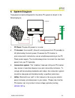
4. System Diagram
The typical connection diagram for the entire PV system is shown in the
following figure.
1.
PV Panel
: Provide DC power to
inverter
2.
PV
-Inverter
: Converts DC (Direct Current) power from PV panel(s) to
AC (Alternating Current) power. Because the PV-Inverter is
grid-connected it controls the current amplitude according to the PV
Panel power supply. The inverter always tries to convert the maximum
power from your PV panel(s).
3.
Connection system
: This “interface” between Utility and PV-Inverter
may consist of electrical breaker, fuse and connecting terminals. To
comply with local safety standards and codes, the connection system
should be designed and implemented by a qualified technician.
4.
Utility:
Referred to as “grid” in this manual, is the way your electric
power company provides power to your place. Please note that the
PV-Inverter can only connect to low-voltage systems (namely,
230VAC/50Hz
).
Summary of Contents for CPS SC1.5KTL
Page 2: ......
Page 42: ...Edition 3 0E 2010 07 40 VDE Certificate European models ...


