background image


Edition 3.0E, 2010/07 

 6 

2.  Limited Warranty 

The Inverter comes with a standard

 5-year warranty.

 An optional extended 

warranty is available for purchase before the unit is delivered to the end user.  

This warranty includes all defects of design, components and manufacturing.  

Excluded from warranty are damages due to: 


Breaking the product seal (opening the casing)  


Improper transportation and delivery 


Unqualified persons opening the unit 


Improper installation 


Unauthorized modification, testing or repairing 


Use and application beyond the definition in this manual 


Application beyond the scope of safety standards (VDE, UL etc.) 


Acts of nature such as lighting, fire, storm etc.  


The right to repair and/or replace the unit is at the manufacturers’ discretion.  

Any damages discovered during installation should be submitted via a 

written damage report within

 5 working days

 of receiving the PV-Inverter.  

Manufacturer are not responsible for damages beyond the scope of this 

warranty.


Summary of Contents for CPS SC1.5KTL

Page 1: ...CHINT Grid PV Inverter CPS SC1 5KTL CPS SC2KTL CPS SC2 8KTL CPS SC4KTL CPS SC4KTL O Installation and Operation Manual Version 3 0E 2010 07 ...

Page 2: ......

Page 3: ... instructions 10 Opening the package 10 Before installation 10 Mounting PV Inverter to the wall 12 Connecting to the grid AC utility 15 Connect to PV Panel DC input 16 Checking 17 4 System Diagram 18 5 Operation of PV Inverter 19 Modes of operation 19 Front Panel arrangement 19 Front Panel 20 LCD Display Sequence 22 ...

Page 4: ... Display information 24 LED 30 7 Communications 31 8 Trouble shooting 33 9 Specifications 35 Electrical 35 Typical Efficiency Charts vs Load 36 10 Disposal 37 11 Contact Information 38 12 Regulation Certificate 39 Compliance Standards 39 VDE Certificate European models 40 ...

Page 5: ...i io on n a an nd d s sa af fe e o op pe er ra at ti io on n o of f t th hi is s u un ni it t B Be e s su ur re e t to o r re ea ad d t th hi is s m ma an nu ua al l c ca ar re ef fu ul ll ly y b be ef fo or re e u us si in ng g If you encounter any problems during installation or operation of this unit first check this manual before contacting your local dealer or representative Instructions insi...

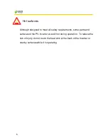
Page 6: ...i ic c s sh ho oc ck k E Ev ve en n a af ft te er r t th he e u un ni it t i is s d di is sc co on nn ne ec ct te ed d f fr ro om m t th he e g gr ri id d a an nd d p ph ho ot to ov vo ol lt ta ai ic c p pa an ne el ls s h hi ig gh h v vo ol lt ta ag ge es s m ma ay y s st ti il ll l e ex xi is st t i in ns si id de e t th he e P PV V I In nv ve er rt te er r D Do o n no ot t r re em mo ov ve e t ...

Page 7: ...d to meet all safety requirements some parts and surfaces of the PV Inverter are still hot during operation To reduce the risk of injury do not touch the heat sink at the back of the Inverter or nearby surfaces while it is operating ...

Page 8: ...nd delivery Unqualified persons opening the unit Improper installation Unauthorized modification testing or repairing Use and application beyond the definition in this manual Application beyond the scope of safety standards VDE UL etc Acts of nature such as lighting fire storm etc The right to repair and or replace the unit is at the manufacturers discretion Any damages discovered during installat...

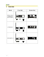
Page 9: ...7 1 Overview Model Front View Bottom View CPS SC1 5KTL CPS SC2KTL CPS SC2 8KTL CPS SC4KTL CPS SC4KTL O ...

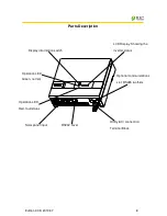
Page 10: ...tion Optional communications slot RS485 others LCD Display Showing the inverter status Solar panel input Utility AC connection Terminal Block RS232 cover Operation LED Red fault status Operation LED Green normal Display information switch ...

Page 11: ...s of the same size Embedded LCD display showing complete status information Natural convection cooling Quiet fan less design Stylish modern casing Compact small profile High reliability Easy installation Maintenance free Standard RS 232 optional RS 485 and others Embedded ENS meets VDE 0126 1 1 No external GFCI breaker is required ...

Page 12: ... un ni it t t to o w we et t o or r m mo oi is st t c co on nd di it ti io on ns s A Al lt th ho ou ug gh h t th he e C CP PS S S SC C4 4K KT TL L O O i is s d de es si ig gn ne ed d f fo or r o ou ut td do oo or r a ap pp pl li ic ca at ti io on n I IP P6 65 5 h ho ow we ev ve er r w we e r re ec co om mm me en nd d n no ot t e ex xp po os si in ng g t th he e P PV V I In nv ve er rt te er r t to...

Page 13: ... nv ve er rt te er r c ca an n b be e i in ns st ta al ll le ed d a an nd d o op pe er ra at te ed d a at t l lo oc ca at ti io on ns s w wh he er re e t th he e a am mb bi ie en nt t t te em mp pe er ra at tu ur re e i is s u up p t to o 5 55 5 C C H Ho ow we ev ve er r f fo or r o op pt ti im ma al l o op pe er ra at ti io on n i it t i is s r re ec co om mm me en nd de ed d t th ha at t t th he...

Page 14: ...tical surface that can support the PV Inverter 2 PV Inverter requires adequate cooling space Allow at least 30cm space above and below the inverter 3 Using the mounting frame as a template drill 4 holes as illustrated in the following figures 4 Fix the mounting frame as the figure shows ...

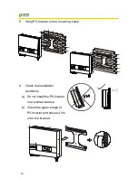
Page 15: ... Hang PV Inverter on the mounting frame 6 Check the installation conditions a Do not install the PV Inverter on a slanted surface b Check the upper straps of PV Inverter and ensure it fits on to the bracket ...

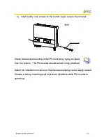
Page 16: ...e er rt te er r s sh ho ou ul ld d r re em ma ai in n f fi ir rm ml ly y a at tt ta ac ch he ed d S Se el le ec ct t t th he e i in ns st ta al ll la at ti io on n l lo oc ca at ti io on n s so o t th ha at t t th he e s st ta at tu us s d di is sp pl la ay y c ca an n b be e e ea as si il ly y v vi ie ew we ed d C Ch ho oo os se e a a s st tr ro on ng g m mo ou un nt ti in ng g w wa al ll l t to ...

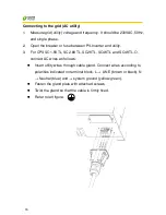
Page 17: ...ility 3 For CPS SC1 5KTL SC2 8KTL SC2KTL SC4KTL and SC4KTL O connect AC wires as follows Insert utility wires through cable gland Connect wires according to polarities indicated on terminal block L LINE brown or black N Neutral blue and system ground yellow green Fasten the gland plate with attached screws Twist the gland so that the cable is firmly fixed Refer to left figure ...

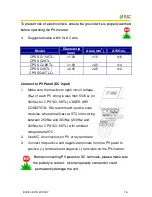
Page 18: ... than 500VDC or 450VDC for CPS SC1 5KTL UNDER ANY CONDITION We recommend use the solar modules whose total UMPP at STC in the string between 250VDC and 350VDC 200VDC and 320VDC for CPS SC1 5KTL with ambient temperature 25 C 2 Use MC 4 connectors for PV array terminals 3 Connect the positive and negative terminals from the PV panel to positive terminals and negative terminals on the PV Inverter B B...

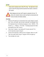
Page 19: ...f f e el le ec ct tr ri ic c s sh ho oc ck k a av vo oi id d t to ou uc ch hi in ng g l li iv ve e c co om mp po on ne en nt ts s a an nd d t tr re ea at t c co on nn ne ec ct ti io on n t te er rm mi in na al ls s c ca ar re ef fu ul ll ly y Checking 1 When the PV panels are connected and their output voltage is greater than 100 VDC but the AC grid is not yet connected the message on the LCD disp...

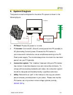
Page 20: ... Panel power supply The inverter always tries to convert the maximum power from your PV panel s 3 Connection system This interface between Utility and PV Inverter may consist of electrical breaker fuse and connecting terminals To comply with local safety standards and codes the connection system should be designed and implemented by a qualified technician 4 Utility Referred to as grid in this manu...

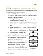
Page 21: ...t enough power from the PV panel monitor internal system status In normal mode the green LED is on 2 Fault mode The internal intelligent controller can continuously monitor and adjust the system status If inverter finds any unexpected conditions such as grid problems or internal failure it will display the information on its LCD and light up the red Fault LED 3 Shutdown mode During periods of litt...

Page 22: ... enters a waiting state and attempts to connect to the grid Normal operation When PV string DC voltage is greater than 150V the inverter operates in the normal state In this state it feeds power to the grid The inverter automatically stops when the PV power is not enough 2 Starting up display sequence Once the PV power is sufficient inverter displays information as shown in the flow chart to the r...

Page 23: ...f after 30 seconds To enable it press the Function key again 6 Contrast control A natural phenomenon of LCD displays is the background color is darker at higher temperatures At higher temperatures the characters may not be easily identified In this case the adjust the contrast as follows a Press the Function key repeatedly until Contrast shows in the display b Hold the Function key down for more t...

Page 24: ...xxx xV AC Current Model SVx000x Sx xx Normal State Contrast Language Feeding wattage wattage Feeding energy of the current day Accumulate energy DC PV voltage Turn on backlight Feeding current Model information F W version Operating status Contrast Adj Language setting LCD display sequence Network AC Frequency ...

Page 25: ... s o ou ut tp pu ut t i is s l lo ow w t th he e f fe ee ed di in ng g D DC C p po ow we er r m ma ay y d dr ri if ft t s sl lo ow wl ly y a as s d do oe es s t th he e A AC C p po ow we er r I It t i is s b be ec ca au us se e P PV V I In nv ve er rt te er r i is s t tr ra ac ck ki in ng g m ma ax xi im mu um m D DC C p po ow we er r c co on nt ti in nu uo ou us sl ly y Accuracy of the reading Th...

Page 26: ...otally shutdown Standby Status Standby Status Standby Input voltage range 200V 260V Initialization waiting Status Waiting Status Warten Input voltage range 260 350V Check grid Status Checking xxxs Status Netz Prüf xxxs In case of PV voltage 350V inverter is checking feeding conditions Feeding grid MPPT Status Normal Status Normalbetriebe Inverter is feeding power After 10 seconds of this display L...

Page 27: ...rid voltage Vac xxx x xxx x xxx x V Uac xxx x xxx x xxx x V Grid voltage in xxx x VAC for 3 phases Grid frequency Frequency xx xHz Frequency xx x Hz Grid frequency in xx x Hz Feeding current Iac xx x xx x xx xA Iac xx x xx x xx xA Feeding current amount in xx x A PV array voltage Vdc xxx xxx xxxV Udc xxx xxx xxxV Input voltage of PV array xxx VDC PV array current Idc xx x xx x xx xA Idc xx x xx x ...

Page 28: ...e output relay is out of order No utility No Utility Kein Netz Utility is not available Input voltage too high PV over voltage DC Überspg Input voltage higher than 800V Inverter Fault Consistent failure Consistent fault Konsistenzfehler The readings of 2 microprocessors are not consistent It could be caused by CPU and or other circuit do not function well Temperature too high Over temperature Über...

Page 29: ...ction problem GFCI Failure FI Fehler The GFCI circuit is abnormal Master and Slave firmware dismatch1 M S Ver Fault M S Ver Fault firmware mismatch between Master and Slave Memory card full Memory Full Memory Full There is not enough space to store data System Information Serial Number SN xxxxxxxxxxxxxxx x SN xxxxxxxxxxxxxxx x 16 characters unique serial number Firmware version Version xx xx xx xx...

Page 30: ...SS GMT xx Time display Audio alarm setting on Audio Alarm On Alarm An Set up audible alarm to on Audio alarm setting off Audio Alarm Off Alarm Aus Set up audible alarm to off Setting Language Language English Sprache Englisch Set up of the display language Setting Language Language ESP Sprache ESP Set up of the display language Setting Language Language German Sprache Deutsch Set up of the display...

Page 31: ...y graph Please Wait Bitte warten data processing Weekly graph No Weekly Records Keine Wochenaufz No data for weekly graph display Error history Error History Fehlergeschichte banner Error history No Error History Keine Fehlergeschi No data for error history display Error history Value N A Value N A fault value is not available Error history Value xxxx xxxx xxxx Value xxxx xxxx xxxx display fault v...

Page 32: ...y only the green LED switches on during operation Their indicated status is explained as follows 1 Power on green LED It lights to indicate that the inverter is running 2 Fault red LED Illuminates during a fault or failure Details of possible faults and their solutions can be found in the previous table ...

Page 33: ... N C 7 N C 8 N C 9 N C N N C C m me ea an ns s N No o C Co on nn ne ec ct ti io on n 2 Optional communications port This port is a very powerful extension The inverter can accept a special card designed for the port only The RS485 card is used to work with EZ logger and in multiple monitoring applications For information of card details please refer to the user manual of each individual card To ge...

Page 34: ... ev ve en nt t r ri is sk k o of f d da am ma ag ge e i it t i is s r re ec co om mm me en nd de ed d t th ha at t o on nl ly y a au ut th ho or ri iz ze ed d p pe er rs so on nn ne el l p pe er rf fo or rm m f fi ir rm mw wa ar re e u up pg gr ra ad de es s ...

Page 35: ...he ground current is too high 2 Unplug the inputs from the PV generator and check the peripheral AC system 3 After the cause is cleared re plug the PV panel and check PV Inverter status 4 If the problem persists please call service Grid Fault 1 Wait for 30 seconds if the grid returns to normal PV Inverter automatically restarts 2 Make sure grid voltage and frequency meet the specifications 3 If th...

Page 36: ... Or move the inverter to a cooler environment 4 If it is not effective call local service Relay Failure DC INJ High EEPROM Failure SCI Failure High DC Bus Low DC Bus Ref 2 5V Fault DC Sensor Fault Inverter Failure GFCI Failure 1 Disconnect ALL PV or PV 2 Wait for few seconds 3 After the LCD switches off reconnect and check again 4 If the message reappears call your local service If there is no dis...

Page 37: ...frequency 47 5 50 2Hz Current distortion 3 Power factor 0 99 Maximum η 95 96 European η 94 95 Environment Protection degree IP 43 IP65 Operating temperature 20 55 Humidity 0 to 95 non condensing Heat Dissipation Convection Power consumption Standby night time 7W 0 1W Acoustic noise Communication Features LCD 1 Line 16 characters Information changeable by Function key on the panel Comm Interface RS...

Page 38: ...0 07 36 Typical Efficiency Charts vs Load CPS SC1 5KTL CPS SC2KTL CPS SC2 8KTL CPS SC4KTL CPS SC4KTL O Note Test equipment tolerances environmental conditions and model specifications may cause actual results to differ ...

Page 39: ... not be disposed of with the household waste Dispose of the PV Inverter at the end of its service life should be done in accordance with the disposal regulations for electronic waste which apply at the installation site at that time Please contact supplier for disposal instruction the contact information could be found in Chapter 11 Contact Information ...

Page 40: ...nce Inverter type Serial number of the PV Inverter Type and number of PV panel connected Fault message Communication method Web http www astronergy com cn index php China 电话 86 571 5603 1888 传真 86 571 5603 2383 E mail sales astronergy com or pr astronergy com North America Tel 01 408 855 8932 Fax 01 408855 8932 E mail andrew li astronergy com Australia Tel 61 7 3868 1999 Fax 61 7 3216 4756 E mail ...

Page 41: ...B DIN EN 61000 6 2 VDE 0839 6 2 EMC interference immunity Grid Interference CPS SC1 5KTL CPS SC2KTL CPS SC2 8KTL DIN EN 61000 3 2 DIN EN 61000 3 3 CPS SC4KTL CPS SC4KTL O DIN EN 61000 3 11 DIN EN 61000 3 12 Grid monitoring EN DIN VDE 0126 1 1 European Models Low Voltage Regulation DIN EN 50178 4 98 VDE 0160 IEC62103 ...

Page 42: ...Edition 3 0E 2010 07 40 VDE Certificate European models ...

Reviews: