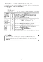
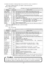
background image


- 30 -


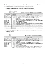
8-6. Process during abnormality 


If there is an error in the contents of the message from the master, respond as follows. 
 

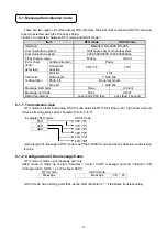
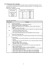
8-6-1. In case of no response


In the following cases, the messages are ignored and no response is given. 

 Transmission error (over run, framing, parity, CRC or LRC) is detected in the message. 

 The slave address during the message is not the self address. 

 The data interval of the message is long. 

RTU mode…When less than 9600bps: 20msec or more 

When 9600bps or more: 5msec or more 

ASCII mode…1 second or more 

 Transmission parameters do not match. 

 Received message exceeds the number of bytes that can be received (Sometimes no response is 

given when the number of messages that can be received are received.) 


Note) When slave address is '0' by write function, it there is no error in the message, message is 

executed but there is no response. If the error mentioned above occurs in the message then 
also there is no response, hence when slave address is '0' the normality/abnormality cannot 
be judged. 


Summary of Contents for KP3000

Page 1: ...Digital Program Controller KP3000 COMMUNICATIONS INTERFACES Retain this manual apart from the instrument and in an easily accessible place Please make sure that this manual is handed to the final user of the instrument ...

Page 2: ......

Page 3: ... 2 Cable for communication 11 7 3 RS 232C connection 14 7 4 Wiring of RS 422A 485 15 8 MODBUS protocol 16 8 1 Message transmission mode 17 8 2 Data time interval 18 8 3 Message configuration 18 8 4 Method of creating a message 25 8 5 Function code 26 8 6 Process during abnormality 30 8 7 Reference table 32 8 8 MODBUS protocol support reference table 53 9 PRIVATE protocol 59 9 1 Difference between ...

Page 4: ...to avoid any trouble This is a Communication instruction manual For general specifications read General instruction manual along with this manual 1 You should not copy or forward fully or partially this document without prior notice 2 The contents of this document may be changed without notice 3 We have taken enough care regarding the contents of this document however if at all you notice a mistak...

Page 5: ...tion It is necessary that the people actually using this controller read this instruction manual and have enough understanding of various precautions and the basic operations of the controller 2 2 Symbol mark The following symbol marks are used in the product itself and in this instruction manual hence understand the meaning of these symbol marks properly Symbol mark Meaning If there is a possibil...

Page 6: ... call data transmission procedure it does not mean that the devices that RS 232C communications interface can be connected unconditionally Hence it is necessary that the designer investigates and confirms the specifications and transmission procedure of the mutual device However if the connection partner is able to program those specifications optionally like the PC the designer by creating the ap...

Page 7: ...ey settings It has the transmission function of measurement data and settings operation function 4 2 PRIVATE Protocol PRIVATE is usual CHINO protocol Switching is done by setting the front key It has the transmission function of measurement data and settings operation function Old instrument of CHINO products is compatible with new instrument however the parameter which can not be set by PRIVATE c...

Page 8: ...or detection CRC 16 RTU mode Data transmission procedure No procedure Usage signal name Sending and receiving data only Without using the control signal 5 2 PRIVATE Communication system Half duplex asynchronous system Polling selecting system Protocol PRIVATE protocol Communication speed 38400 19200 9600 4800 2400bps switching Start bit 1 bit Data length 7 bits Parity bit Even Stop bit 1 bit Trans...

Page 9: ...key Device number For RS 422 485 Select instrument number using key Register using key Setting range 01 to 99 key Communication function Select the following communication function using key Register using key Setting range COM TRANS key Communication Protocol Select the communication protocol mentioned below using key Register it using key Setting range MODBUS RTU MODBUS ASCII PRIVATE key Communi...

Page 10: ...erlap with the other KPs COM NUMBER is displayed using the key Set device number 1 to 99 using key select it and register it using key Precautions Device number should be in a range from 1 to 99 and it should not overlap with the other KPs Initial value 1 In case of RS 232C KP is connected to 1 machine but set the device number Usually initial value can be 1 6 3 Set the communication function COM ...

Page 11: ...cation character COM CHARACTER COM CHARACTER is displayed using key Select communication character using key and register it using key MODBUS RTU Selection Bit length Parity Stop bit Initial value 8BIT NON STOP1 1 8BIT NON STOP2 None 2 8BIT EVEN STOP1 1 8BIT EVEN STOP2 Even 2 8BIT ODD STOP1 1 8BIT ODD STOP2 8bit Odd 2 8BIT NON STOP1 MODBUS ASCII Selection Bit length Parity Stop bit Initial value 7...

Page 12: ... 9 PRIVATE When communication protocol is PRIVATE communication character screen is not displayed Selection Bit length Parity Stop bit Initial value 7BIT EVEN STOP1 7bit Even 1 7BIT EVEN STOP1 ...

Page 13: ...re 4 Always perform the crimp style terminal process One of the causes of communication defect is loss of connection Always process the communication cable terminal using 0 type or Y type crimp style terminal with insulation sleeve Terminal screw of KP line converter is M3 5mm 5 Apply last terminal resistance When using RS 422A 485 communication apply a resistance of 100Ω to the KP place in the la...

Page 14: ...ing Model code RZ CRS6 Cable length is 1 to 15m Specified Connection between PC 25 pin and KP PC 25 pin and line converter Cable 25 pin connector 0 type crimp style terminal RS 232C cable Format Internal wiring Model code RZ CRS2 Cable length is 1 to 15m Specify SD RD SG PC side 25 pin connector Cable Maximum length 15m for RS 232C KP Line converter side RD SD SG Cable Maximum length 15m for RS 23...

Page 15: ...h is 01 to 99m Specified Connection between KPs Cable 0 type crimp style wire 0 type crimp style RS 422A cable For serial connection Format SG Signal grand wiring is available on both sides using 2 wick VCTF wire which is further twisted to 4 wicks Internal wiring Model code RZ CRA1 Cable length is 01 to 99m Specified RDB RDA SDA SDB SG RDB RDA SDA SDB SG RDB RDA SDA SDB SG RDB RDA SDA SDB SG KP s...

Page 16: ...ble Format SG Signal Grand wire is available in both the terminals using 2 wick cable made by twisting CVVS wire It is disconnected and used as there is no SG terminal on the line converter side Internal wiring Model code RZ LEC Cable length is 001 to 200m Specified RDA Black RDB White SG Green Black SA White SB Green SG Line converter side KP side RDA RDB SG SA SB SG ...

Page 17: ...rols the control signal see the instruction manual of the PC that is being used Precautions RS 232C cable length is maximum 15m NEC make PC98 series 9 pin connector is Wiring example 1 and 25 pin connector is connected as shown in Wiring example 2 Wiring example 1 Wiring example 2 25 pin connector for PC PC 98 series KP 25 24 14 15 16 17 18 19 20 21 22 23 13 12 11 10 1 2 3 4 5 6 7 8 9 RS CS DR ER ...

Page 18: ...er Wiring of RS 422A Do not connect the SG wire to FG terminal or grounding terminal of the device Precautions 9 pin connector for PC Wiring process is required 6 7 8 9 1 2 3 4 5 SD RD SG 1 2 3 4 5 6 7 8 RDA SDB RDB SDA KP RDA RDB SDA SDB KP RDA RDB SDA SDB KP RDA RDB SDA SDB Terminal resistance 100Ω Line converter Wiring of RS 485 9 pin connector for PC Wiring process is required 6 7 8 9 1 2 3 4 ...

Page 19: ...le or a device and do not switch ON OFF the power supply during communication If cable or device that makes up the serial interface is removed or power supply is switched ON OFF operation is stopped and error may occur If this is the status it is necessary to reset all the devices that make up the serial interface and redo everything from the beginning 5 Send the next command only after confirming...

Page 20: ...ts Message start code None Colon Message end code None CR LF Data time interval Less than 28 bit time Less than 1 second 8 1 1 Transmission data RTU mode is binary forwarding ASCII mode splits the RTU 8 bit binary into high order and low order 4 bits and garbles each character 0 to 9 A to F Example RTU mode ASCII mode 67H 36H 6 89H 37H 7 ABH 38H 8 39H 9 41H A 42H B As the length of message in RTU ...

Page 21: ...a Error check 8 3 1 Slave address Set the slave address beforehand in a range of 1 to 99 using front key setting Master usually does the transmission with one slave All the connected devices receive in common the message sent from the master However the slave whose slave address matches with the slave address in the command message only responds to that message Slave address 0 is used in message b...

Page 22: ...r value or by fixing the decimal point position make it standard by upper and lower limit of the scale and express it In KP a system of putting the decimal point in a different position is fetched 8 3 4 Reference number In the KP there is a number called Reference number that is allotted and it is required when reading and writing the data KP is categorized depending on its type into Digital input...

Page 23: ... 6 8 type parameter No 7 8 type parameter No 8 System information Program pattern information Program pattern setting editing Operation status information 40008 to 40020 40052 to 40092 40147 40151 40221 to 40224 40271 to 40274 40321 to 40324 40371 to 40374 40421 to 40424 40471 to 40474 40521 to 40524 40571 to 40574 48001 to 48033 49003 to 49049 49055 to 49096 49501 to 49534 7 to 19 51 to 91 146 15...

Page 24: ...e end of the data and calculation is done by the following procedure 1 Initialization FFFFH of CRC 16 data Consider it as X 2 Exclusive OR EX OR of data 1 and X X 3 Shift X one bit to the right X 4 If carry appears get A001H and EX OR If it does not appear go to 5 X 5 Repeat 3 and 4 until shifting is done for 8 times 6 Net data and EX OR of X X 7 Same as 3 to 5 8 Repeat until the end of the data 9...

Page 25: ...sData 0 Get the exclusion of CRC output result and the data that is input usCrcData usData usCrcData Do the CRC calculation Repeat till shifting up to 8 bits is done for iLoopCnt 0 iLoopCnt 8 iLoopCnt Check the existence of carry if usCrcData 0x0001 When carry occurs Shift CRC output result 1 bit to the right usCrcData usCrcData 1 Get the exclusion with A001H usCrcData usCrcData 0xa001 else When c...

Page 26: ...37H 46H 37H Reference LRC calculation program LRC calculation program C language include stdio h include conio h void main void Internal variable declaration unsigned short usData Input data unsigned short usLrcData LRC data int iDummy Dummy variable Initialize the output result of LRC data usLrcData 0 printf Enter hexadecimal data End using q n while scanf x usData 0 Add from the beginning to the...

Page 27: ...zation process etc depending on the change in the measurement range Process contents are mentioned in reference number table Read and write the data in the range of the numbers specified by reference number If data is read and written for the reference numbers that are not specified device operation may get affected Many reference numbers that are not continuous can be read and written however if ...

Page 28: ...Ú It is necessary to confirm the number of bytes of data Data division Starting relative number 125 00H 7DH Number of units 2 00H 02H PTN selecting pattern No and STP executing step No are stored in reference number 30103 to 30014 See section 8 3 4 table 3 From the reference table it is understood that PTN is stored in 30126 and STP is stored in 30127 See section 8 7 For details on reading the PTN...

Page 29: ... 1 data 1 byte LSB DO side of each data becomes a digital data of the smallest number If the units that are to be read are not in multiples of 8 then the bits that are not required become 0 Example Reading the digital settings value reference number 10005 of slave 1 Reference number 10005 Data 0 System normal RTU mode Master Device Device Master Normal Slave address 01H Slave address 01H Function ...

Page 30: ...s L 03H Executing hour H 00H CRC L 3EH Executing hour L 0AH CRC H 5DH Executing minute H 00H Executing minute L 14H CRC L 61H CRC H 5CH LRC ACH LRC EDH Note Starting number Relative number is Reference number 40001 Note Data count is the number of bytes of data It differs from request units In the example request unit count is 3 units data count is 6 units Note There is a limitation on the number ...

Page 31: ...nse the response is same as command message Note If slave address is considered as 0 all the slave machines execute this command However no slave machine responds 8 5 5 Loop back test Function code 08 08H Perform transmission check between master slaves Respond in accordance to the diagnosis code that is specified In this device perform return check to send the received data as it is and diagnosis...

Page 32: ...ster Normal Slave address 01H Slave address 01H Function code 10H Function code 10H Starting number H 00H Starting number H 00H Starting number L 07H Starting number L 07H Number of units H 00H Number of units H 00H Number of units L 03H Number of units L 03H Data count 06H CRC L 31H Initial data H 00H CRC H C9H Initial data L 01H Second data H F8H Second data L 30H Third data H 35H Third data L 8...

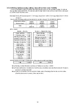
Page 33: ...e is long RTU mode When less than 9600bps 20msec or more When 9600bps or more 5msec or more ASCII mode 1 second or more Transmission parameters do not match Received message exceeds the number of bytes that can be received Sometimes no response is given when the number of messages that can be received are received Note When slave address is 0 by write function it there is no error in the message m...

Page 34: ...fied number of units When requested number of data units is 0 When received specified data count and actual data count do not match 11H Other than setting value range When numeric value that is out of setting range is mentioned in the reference table 12H Cannot be set When operation screen and drive pattern No are set at the time other than that of resetting When operation screen and drive pattern...

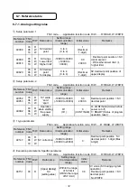
Page 35: ...40052 40053 03 06 16 R W W SV scale zero span 19999 to 30000 19999 to 30000 0 0 2000 0 Decimal point position SV decimal point 40092 03 06 16 R W W Operation when starting the power supply 0 1 0 1 0 CONTINUE 0 CONTINUE Status before power cut off 1 READY Status of program operation reset 1 type parameter FNC code Application function code R W R READ W WRITE Reference number FNC Code R W Data name ...

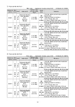
Page 36: ... Unit Every time unit 1 In case of H M hours minutes H hours 2 Incase of M S minutes seconds M minutes 8 type parameter No 2 FNC code Application function code R W R READ W WRITE Reference number FNC Code R W Data name Setting range Communication range Initial value Remarks 40271 03 06 16 R W W 8 type parameter Time signal ON No 2 Hours or Minutes 0 to 999 0 to 999 000 Hours or minutes Can be writ...

Page 37: ... Unit Every time unit 1 In case of H M hours minutes H hours 2 Incase of M S minutes seconds M minutes 8 type parameter No 4 FNC code Application function code R W R READ W WRITE Reference number FNC Code R W Data name Setting range Communication range Initial value Remarks 40371 03 06 16 R W W 8 type parameter Time signal ON No 4 Hours or Minutes 0 to 999 0 to 999 000 Hours or minutes Can be writ...

Page 38: ... Unit Every time unit 1 In case of H M hours minutes H hours 2 Incase of M S minutes seconds M minutes 8 type parameter No 6 FNC code Application function code R W R READ W WRITE Reference number FNC Code R W Data name Setting range Communication range Initial value Remarks 40471 03 06 16 R W W 8 type parameter Time signal ON No 6 Hours or Minutes 0 to 999 0 to 999 000 Hours or minutes Can be writ...

Page 39: ... Unit Every time unit 1 In case of H M hours minutes H hours 2 Incase of M S minutes seconds M minutes 8 type parameter No 8 FNC code Application function code R W R READ W WRITE Reference number FNC Code R W Data name Setting range Communication range Initial value Remarks 40571 03 06 16 R W W 8 type parameter Time signal ON No 8 Hours or Minutes 0 to 999 0 to 999 000 Hours or minutes Can be writ...

Page 40: ...ue Remarks 48001 03 06 16 R W W Display back light 0 1 2 0 1 2 2 AUTO 0 Green 1 Orange 2 AUTO Normal Green Alarm activation Orange 48002 03 06 16 R W W Display contrast 0 to 100 0 to 100 50 48003 03 06 16 R W W Key backlight 0 1 2 0 1 2 0 AUTO 0 AUTO In case of pressing the key lighting extinction after 30 seconds 1 OFF Always extinction 2 ON Always lighting ...

Page 41: ...OP RUN STOP operation 02h ADV ADVANCE operation 03h RESET RESET operation 04h WAIT WAIT operation 05h FAST FAST operation 06h PTN1 Pattern No selection BCD_1 07h PTN2 Pattern No selection BCD_2 08h PTN4 Pattern No selection BCD_4 09h PTN8 Pattern No selection BCD_8 0Ah PTN10 Pattern No selection BCD_10 0Bh PTN20 Pattern No selection BCD_20 DO External signal outnput 00h no setting 01h TS1 Time sig...

Page 42: ...external signal input output for lower order 8 bits and function of terminal for higher order 8 bits High order 8 bits Low order 8 bits WRITE FNC_06 FNC_16 WRITE as type of terminal of external signal input output for lower order 8 bits High order 8 bits are region of Reserve High order 8 bits Low order 8 bits Type of terminal Function of terminal 15 8 7 0 Reseve Function of terminal 15 8 7 0 ...

Page 43: ...r Reading Writing of program pattern reference 49005 to 49045 1 STP00 pattern 0 to 19 STP19 pattern 19 Set before reading writing of pattern information Written step number is stored until tuning off the power of instrument Reading writing of step number of this reference is dedicated data for reading writing program pattern information by communications When read write step number during program ...

Page 44: ...inal step final step 1 When write to the next step of the final step step is added to end of the pattern 49010 03 06 16 R W W Program pattern SV No 0 to 8 0 to 8 STEP1 1 No 1 From STEP2 0 No 0 0 No 0 continue of the prior step number 1 to 8 No 1 to 8 Read write after writing reference 49003 and 49004 Writing is not possible when reference 49004 is step 0 or after the final step 49020 49021 49022 4...

Page 45: ...stination pattern No 0 to 19 0 to 19 0 Non link 0 Non pattern link 1 Link to pattern 1 19 Link to pattern 19 Read write after writing reference 49003 Setting of step No of reference 49004 is not necessary 49048 03 06 16 R W W Time unit 0 1 0 1 0 H M 0 H M Hours Minutes 1 M S Minutes Seconds When program operation is other than during RESET writing is not possible 49049 03 06 16 R W W SV during res...

Page 46: ...program pattern is written When write to pattern 1 set 01 0001H Step No H 00H Step No L 01H Reference number 49004 Set the step No of program pattern is written When write to pattern 1 set 01 0001H CRC L 6CH CRC H F9H Set the cord for error check When it is MODBUS_RTU protocol set the error check value of CRC 16 Procedure 2 Notify parameter type of step information is performed reading master inst...

Page 47: ...Decimal notation 1111 SV decimal point 1 111 1 Time hours or minutes H 00H Time hours or minutes L 16H Reference number 49007 Acquire high order HHH of time 0016H Decimal notation 22 Time minutes or seconds H 00H Time minutes or seconds L 21H Reference number 49007 Acquire low order LL of time 0021H Decimal notation 33 Not Use 00H Not Use 00H Reference number 49009 is not in use reference number E...

Page 48: ...mand Setting contents Slave address 01H Set the instrument number MODE 8 of sending command to KP Function cord 10H Set the function cord 16 10H for writing multiple analog setting values Starting number H 23H Ending number L 2DH Specify starting number beginning number of reference is written continuous Set the reference number 49006 49006 40001 9005 232DH Quantity H 00H Quantity L 05H Set five 0...

Page 49: ... 1 Pattern 1 Reading writing of pattern No is performed program operation 1 PTN01 Pattern 1 to 30 PTN19 pattern 30 Writing is not possible in the following cases When pattern selection system is other than COM in the case of with pattern selection input option 49067 03 06 16 R W W Operation screen Program operation READ 1 2 3 4 5 6 1 2 3 4 5 6 WRITE 1 2 4 6 1 2 4 6 1 RESET READ FNC_03 1 RESET Rese...

Page 50: ...umber in existence reference 49040 is other than 0 step Writing pattern copy is not possible After clear in copy destination pattern reference 49094 perform pattern copy When copy destination pattern No and copy source pattern No is same writing pattern copy is not possible Continuous writing is not performed from reference 49093 to 49096 by FNC16 function cord 49094 03 06 16 R W W Pattern step ed...

Page 51: ...wing is the example of adding new step between step 4 and step 5 of pattern 10 Command of step adding Issue of command of FNC code 0 6 reference No 49095 setting data 0A04h 0Ah pattern No pattern 10 04h step No step 4 Example of command MODBUS_RTU slave address instrument number 01 010623860A0464C4 Before step adding Pattern 10 Step 0 SV 0 0 Step 1 SV 10 0 TIME 1 01 SV No No 1 Step 2 SV 20 0 TIME ...

Page 52: ...lete step is not possible Supplemental remarks The following is the example of deleting step 3 of pattern 10 Command of step deleting Issue of command of FNC code 0 6 reference No 49096 setting data 0A03h 0Ah pattern No pattern 10 03h step No step 3 Example of command MODBUS_RTU slave address instrument number 01 010623870A0374C6 Before step deleting Patten 10 Step 0 SV 0 0 Step 1 SV 10 0 TIME 1 0...

Page 53: ...0 1 2 3 4 0 MASTER KEY 0 MASTER KEY front key 1 MASTER EXT external input 2 SLAVE EXT synchronous method external input 3 MASTER COM communication 4 FREE front key external input communication Writing is possible in case of with external signal input 49517 03 06 16 R W W Select pattern system 0 1 2 3 0 1 2 3 0 KEY 0 KEY font key 1 EXT external input 2 COM communication 3 FREE front key external in...

Page 54: ...0131 of time display screen 30129 04 R Time display screen Patten progress time Minutes or Seconds Minutes or Seconds of program pattern elapsed remaining time 00 to 23 0 to 23 Hours 00 to 59 0 to 59 Minutes or Seconds FFFFh Time display digit over over the 999 23 D H display Unit Every time unit reference 30131 of time display screen 30130 04 R Time display screen Time display system MODE2 Time d...

Page 55: ...nction TS1 or TS2 or or TS8 1 Time signal ON lighting TS1 or TS2 or or TS8 READ after relating bit 0 to 7 of 16 bits data to time signal 1 to 8 Low order 8 bits 8 7 3 Digital input data READ only System abnormality status FNC code Application function code R W R READ W WRITE Reference number FNC code R W Data name Detailed explanation 10005 02 R System abnormality 0 Normal 1 Correction data abnorm...

Page 56: ...0116 40166 40017 40067 40117 40167 40018 40068 40118 40168 40019 40069 40119 40169 40020 SV decimal point for display 40070 40120 40170 40021 40071 40121 40171 40022 40072 40122 40172 40023 40073 40123 40173 40024 40074 40124 40174 40025 40075 40125 40175 40026 40076 40126 40176 40027 40077 40127 40177 40028 40078 40128 40178 40029 40079 40129 40179 40030 40080 40130 40180 40031 40081 40131 40181 ...

Page 57: ...ime signal ON Minutes or seconds 40322 Time signal ON Minutes or seconds 40372 Time signal ON Minutes or seconds 40223 Time signal OFF Hours or minutes 40273 Time signal OFF Hours or minutes 40323 Time signal OFF Hours or minutes 40373 Time signal OFF Hours or minutes 40224 Time signal OFF Minutes or seconds 40274 Time signal OFF Minutes or seconds 40324 Time signal OFF Minutes or seconds 40374 Ti...

Page 58: ... Time signal ON Minutes or seconds 40522 Time signal ON Minutes or seconds 40572 Time signal ON Minutes or seconds 40423 Time signal OFF Hours or minutes 40473 Time signal OFF Hours or minutes 40523 Time signal OFF Hours or minutes 40573 Time signal OFF Hours or minutes 40424 Time signal OFF Minutes or seconds 40474 Time signal OFF Minutes or seconds 40524 Time signal OFF Minutes or seconds 40574 ...

Page 59: ...inal No 21 49021 Time signal 2 No 40622 40722 48022 External signal allocation Terminal No 22 49022 Time signal 3 No 40623 40723 48023 External signal allocation Terminal No 23 49023 Time signal 4 No 40624 40724 48024 External signal allocation Terminal No 24 49024 Time signal 5 No 40625 40725 48025 49025 Time signal 6 No 40626 40726 48026 External signal allocation Terminal No 26 49026 Time signa...

Page 60: ...0119 49070 49520 30020 30120 49071 49521 30021 30121 49072 49522 30022 30122 49073 49523 30023 30123 49074 49524 30024 30124 49075 49525 30025 30125 49076 49526 30026 30126 PTN Pattern No in selection 49077 49527 30027 30127 STP Step No in execution 49078 49528 30028 30128 Progress time Hours or Minutes 49079 49529 30029 30129 Progress time Minutes or Seconds 49080 49530 30030 30130 Time display s...

Page 61: ...16 117 167 10017 10117 118 168 10018 10118 119 169 10019 10119 120 170 10020 10120 121 171 10021 10121 122 172 10022 10122 123 173 10023 10123 124 174 10024 10124 125 175 10025 10125 126 176 10026 10126 127 177 10027 10127 128 178 10028 10128 129 179 10029 10129 130 180 10030 10130 131 181 10031 10131 132 182 10032 10132 133 183 10033 10133 134 184 10034 10134 135 185 10035 10135 136 186 10036 101...

Page 62: ...k communicate with that device according to the procedure explained in Communication format Precautions To avoid accidents always read these contents and understand them 1 Always send the device numbers in 2 digits from 01 to 99 2 Do not use the device number 00 3 Only the specified device responds within 1 second 4 When the device of the specified device number does not exist then there is no res...

Page 63: ...ays read these contents and understand them 1 By using this command the data link of all the devices that are connected is released and following data link is established 2 Data link of each device which is connected is released within 10msec from when this command given hence for sending it further from the PC a time of 10msec or more is necessary 3 EOT is control code and it is expressed as hexa...

Page 64: ...m of target range data is split into high and low order 4 bits and are converted to characters 30 to 39 41 to 46H 0 to F and is kept in high order and low order sequence 2 characters When adding parity to BCC the parity of BCC itself is considered BCC is not added in positive and negative response Nor it is added to ENQ ACK EOT BCC is added and checked for both sending and receiving 31 32 2C 30 03...

Page 65: ...ey or the corresponding mode In case of data request command from high order PC KP outputs the data regardless of lock no lock status However pattern setting data is output in case of RESET only When KP receives a data request from high order PC if the request is correct the data is sent If the request is incorrect or if data sending is not possible a negative response is sent When KP receives par...

Page 66: ...ata Program pattern data request Data request for each step Individual setting parameter request STX 1 4 ETX BCC CR LF 1 to 8 Parameter No When parameter is 8 types When 91 to 98 PID9 When 1 Parameter is 1 type Parameter type No 1 1 parameter type No is a number given to setting parameter and is indicated in section 9 3 5 Data request by specifying 1 setting parameter Program pattern setting statu...

Page 67: ...econd D dummy ETX BCC CR LF Setting program pattern data output In case of reset only In KP3000 all the parameter No excluding TS become the dummy data i Step 0 output STX 3 1 0 ETX BCC CR LF Pattern No Step No Start SV 0 Start SV 1 Start PV ii Step n output STX 3 2 Pattern No Step No SV Time Repeat count 0 Repeat start step Un set step PID ALM OPL OSL TS1 TS2 TS3 TS4 TS5 No No No No Waiting time ...

Page 68: ...meter setting format in case of setting from PC in KP See 9 3 5 However as the number of digits of the data differ see Appendix 1 Communication format list for the details Program pattern setting status output STX 5 ETX BCC CR LF Setting step count 0 Not set Pattern No Device status output STX 6 ETX BCC CR LF 1 Controller 2 Setter 0 Setter 1 Full multi input 2 4 wire type Input Output 1 1 61 65 EM...

Page 69: ...S4 TS5 Time signal 0 OFF 1 ON Error Waiting time alarm ETX BCC CR LF In KP3000 everything except TS becomes the dummy data Status 2 Output STX 9 RUN 0 M S 0 Master 1 RUN 1 Slave STOP 0 FNC key 0 Non lock 1 STOP LOCK 1 Lock RESET 0 AT dummy 1 RESET END 0 WAIT dummy 1 END ADV 0 MAN2 dummy 1 ADV MAN1 dummy CONST dummy ETX BCC CR LF In KP3000 a part of the data becomes the dummy data ...

Page 70: ...OP 3 ADV 4 RESET 5 Select pattern Note When external drive input select pattern input options are attached it is necessary to set the program drive system select pattern system to COM communication in mode 1 Mode Lock release lock STX 2 7 ETX BCC CR LF 1 2 3 4 5 6 7 8 Mode 0 FNC key 0 Non lock 1 Lock Time display system Mode 1 lock STX 2 8 ETX BCC CR LF 1 Elapsed step 2 Elapsed pattern 3 Remaining...

Page 71: ...X BCC CR LF Pattern Step Output in case of END No No 0 Output 0 200 Fixed control Link destination pattern No 00 No link In KP3000 mode 4 is locked using communication and 0 is set in END output Parameter No setting STX 3 4 Pattern Step PID ALM OPL OSL Waiting time number No No No No No No ETX BCC CR LF TS1 TS2 TS3 TS4 TS5 00 ALL OFF Set 00 in case of no TS 01 No 1 02 Repeat No 1 16 Repeat No 8 99...

Page 72: ...rs minutes minutes seconds is a period SV decimal point Mode 5 lock 32 STX 32 ETX BCC CR LF Note Differs from display SV decimal point SV during Reset Mode 2 lock 49 STX 49 ETX BCC CR LF Reserve Mode 5 lock 51 STX 51 ETX BCC CR LF Initial value 0 Initial value 5 Note Only when read respond by initial value Do not change the settings in case of write SV scale Mode 5 lock 52 STX 52 ETX BCC CR LF MIN...

Page 73: ... reception buffer 16 Numeric value Cannot recognize as numerals 20 Data Undefined numeric value is received Numeric value is out of range 21 L H error Greater and smaller relation is reversed 22 SV RANG error It is set out of SV RANG 23 SV scope error 24 Z S error Greater and smaller relation is reversed 25 Linear range error 30 Program drive ADV STOP was done during reset 31 Pattern was selected ...

Page 74: ...n except in case of RESET 51 Copy destination is not cleared 52 Copy source pattern is not set 53 Clear pattern Clear pattern except during RESET 54 Read pattern Read requested the pattern data except during RESET 55 Read requested the unset step 60 RUN PTN No Unset pattern is RUN Link destination includes the unset pattern 61 RUN Repeat step Repeat step setting of the pattern that was RUN is an e...

Page 75: ...st 1 Response Response 1 1 Normal within 100msec Negative response Negative response High order Command Negative response Response 2 2 Negative response Positive response Response 3 Copy pattern 2 Normal within 100msec 3 Normal within 100msec High order Setting 4 Positive response During normal times 4 4 Normal within 100msec During abnormality Negative response ...

Page 76: ...P for the request and setting from PC is carried out after a certain time In other words if there is no response from KP after a fixed time it is necessary send a request and settings from the PC again For timer time when it is resend see the time chart Not clear High order LF CR S T X 5 5 Normal within 100msec Negative response Negative High order S T X 6 Character count Negative response 6 128 c...

Page 77: ...e unit Transmission data contents MODBUS protocol Transmission Remote Between DB KP series MODEBUS protocol Master unit transmits Run Ready status SV No and remote SV data no decimal point information and then slave unit receives it PRIVATE protocol Transmission Remote Between KP and controller of out company PRIVATE protocol Master unit transmits remote SV data with decimal point information and ...

Page 78: ... Transmission code ASCII ASCII mode PRIVATE mode or Binary RTU mode Error check Check sum Ú1 For PRIVATE mode CRC 16 For RTU mode LRC For ASCII mode Usage signal name Send or receive data only without using control signal Ú1 Check sum BCC Check sum means total sum of characters after STX up to ETX is calculated lower order 8 bits are split into high and low order 4 bits and are converted to charac...

Page 79: ...by slave address 0 in MODBUS format mentioned earlier Precautions When connecting KP using communication transmission and DB using communication remote the communication speed and transmission protocol must be the same If analog remote and communication remote are used simultaneously analog remote takes precedence Analog transmission type and communication transmission type can be set separately I...

Page 80: ...ve unit Communication transmission KP Master unit RDA RDB SDA SDB RDA RDB SDA SDB Terminal resistance 100Ω RDA RDB SDA SDB RDA RDB SDA SDB SG SG SG SG Communication transmission KP Master unit Communication remote DB Slave unit RD SD SG RD SD SG Communication transmission KP Master unit SA SB SG Communication remote DB Slave unit SA SB SG Communication remote DB Slave unit SA SB SG Terminal resist...

Page 81: ...munication remote As there is no error in analog division remote control with good precision is possible If remote shift of DB is used temperature slope can be held in multizone Sensor DB Slave unit Sensor Sensor KP Master unit Zone Zone Zone SV remote Operation terminal Operation terminal Operation terminal DB Slave unit SV remote DB Slave unit SV remote SV transmission ...

Page 82: ...C CR CR 0DH LF LF 0AH Format Communication Item 1 2 3 4 5 6 7 8 9 10 11 12 13 14 15 16 17 18 19 20 21 22 23 24 25 26 27 28 29 30 Real data request SX 1 1 EX BC D BC F CR LF SX 1 PTN STP Dummy SV TIME Dummy Dummy EX BC BC CR LF Response output MV2 Execution parameter request SX 1 2 EX BC E BC F CR LF SX 2 SV Dummy Dummy Dummy Dummy Dummy Dummy Dummy Dummy Dummy Dummy Dummy Dummy EX BC BC CR LF Resp...

Page 83: ...ount SX 1 4 EX BC BC CR LF Individual settings Parameter request Type No SX 1 5 EX BC BC CR LF Program pattern Setting status request PTN SX 5 EX BC BC CR LF Response output PTN STP count Device status request SX 1 6 EX BC 2 BC 0 CR LF Response output SX 6 EX BC BC CR LF Mode lock Status request SX 1 7 EX BC 3 BC 0 CR LF SX 7 EX BC BC CR LF Response output FNC 0 1 2 3 4 5 6 7 8 Status 1 Request SX...

Page 84: ... BC BC CR LF SX 3 1 0 0 0 EX BC BC CR LF Step 0 setting PTN Start SV SX 3 2 EX BC PTN STP SV Time Step n setting BC CR LF SX 3 3 0 EX BC BC CR LF END step setting PTN STP Link SX 3 4 0 0 0 0 0 0 0 PTN STP TS1 EX BC BC CR LF Parameter No setting TS2 TS3 TS4 TS5 SX 3 5 EX BC BC CR LF Step repeat setting PTN Start End Count SX 3 6 EX BC BC CR LF Pattern repeat setting Count Pattern copy SX 3 7 EX BC ...

Page 85: ... 82 Format Communication Item 1 2 3 4 5 6 7 8 9 10 11 12 13 14 15 16 17 18 19 20 21 22 23 24 25 26 27 28 29 30 SX SX 1 1 9 9 EX EX BC BC BC BC CR CR LF LF Time signal No ON_Time OFF_Time ...

Page 86: ...ion item 1 2 3 4 5 6 7 8 9 10 11 12 13 14 15 16 17 18 19 20 21 22 23 24 25 26 27 28 29 30 SV during Reset SX SX 4 4 9 9 EX BC BC EX CR BC LF BC CR LF SV scale SX SX 5 5 2 2 EX BC BC CR LF EX BC BC CR LF Scale MIN Scale MAX ...

Page 87: ......

Page 88: ...32 8 KUMANO CHO ITABASHI KU TOKYO 173 8632 Telephone 81 3 3956 2171 Facsimile 81 3 3956 0915 E mail inter chino co jp Printed in Japan ...

Reviews: