


チコーエアーテック株式会社
Copyright CHIKO AIRTEC CO., LTD. 2009
8
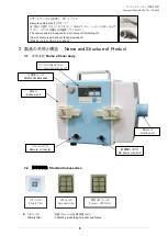
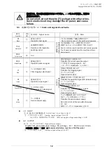
②
運転圧力
Suction static pressure level
現在の運転圧力(k
Pa
)表示しています。
Measure unity kPa indicates current pressure when functioning.
気圧の変化や温度条件により圧力表示は
-0.2
k
Pa
~
0.2
k
Pa
の範囲で変化します。
The pressure representation changes within the range from -0.2 to 0.2. Because there is a
change in the atmospheric pressure and the temperature.
また、外部ノイズの影響により一時的に圧力数値が変化する場合があります。
And the pressure representation might temporarily change because it is influenced by the
extrinsic noise.
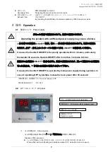
③
能力レベル
VOLUME
吸込力を調整するボタンです。
5
段階の
LED
によりその能力を点灯して知らせます。
Suction control button. The green LED indicates 5 speed grades.
Lo
:
1
回押すごとに1レベル降下(最小約
50
%)
Lo
:
Push here to lower gradually suction speed.
Minimum(Lo) : 50 % power
Hi
:
1
回押すごとに
1
レベル上昇(最大約
100
%)
Hi
:
Push here to increase gradually suction speed.
Maximum(Hi) : 100 % power
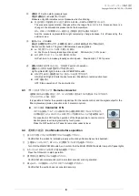
④
運転・
ON/OFF(
タクトスイッチ
)
ON/OFF switch of operation
運転スイッチが入ると赤色のランプが点灯します。
Light up(Red LED light) to turn on the OPERATION switch
ON
(赤色
LED
):運転開始となり、能力レベルを設定できます。
ON (Red LED light): Starts the dust collector. Possibility to record suction level
OFF
:運転停止
OFF
:
Stops operation of
the dust collector.
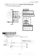
4.3
リモートコネクタについて
Remote connector
遠隔操作のための運転信号入力や、フィルタ交換の信号出力などを取り出すことができます。
(オスコネクタコード
3M
別売)
It is possible to transfer the operation signal input for the remote control, and the signal output for the
filter replacement.(male connection cord: 3 meters in option).
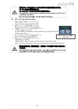
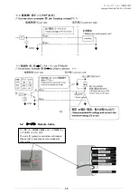
コネクタ接続
Connector
ON
コネクタを接続して、
AT
パネル側の操作から遠隔操作に移行することができます。
その際の能力レベルは
AT
パネル
OFF
ボタンで記憶されたレベルで運転開始します。
It is possible to shift from the operation of the AT-panel side to remote control.
Suction power level is programmed by touch panel.
Press the OFF switch on AT panel to remember capacity level.
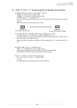
4.4
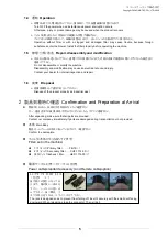
運転前の確認
Confirmation before operation
①
据え付け状態にがたつき等の異常がないかを確認してください。
Confirm that the product is installed properly without any abnormality such as backlash.
②
主電源スイッチを入れて、
AT
パネルの主電源ランプの点灯を確認してください。
Turn ON the MAIN POWER switch, and confirm that the MAIN POWER indicator lamp of AT-panel lights.
③
AT-
パネルの
ON
スイッチを押して運転を確認して下さい。
Press the ON switch to start operation.
④
異常音が
(
金属音など
)
ないか確認してください。
Confirm that abnormal sounds (such as metallic sounds) are not generated.
⑤
吸込みホ-スの接続がしっかりつながれているか確認してください。
Confirm that the suction hose is connected securely.