


チコーエアーテック株式会社
Copyright CHIKO AIRTEC CO., LTD. 2009
4
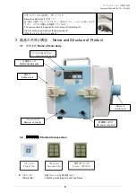
1
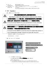
製品使用上のご注意
Cautions on Using Product
1.1
全般
General
設置、接続、運転、操作、点検、故障診断の作業は、取扱説明書の内容に従い、適切に行って下さい。
誤った作業を行うと、火災・感電・けがの原因になります。
Perform installation, connection, operation, manipulation, inspection and failure diagnosis work properly in
accordance with the instruction manual. Incorrect work may cause fire, electrical shock and injury.
1.2
運搬・設置・保管・輸送の条件
The condition of carry installation, transportation and safekeeping
輸送・保管については安全な場所で、温度
-10
℃~
60
℃ 湿度
80%
以下の範囲として下さい。
For transport and storage, keep in a safe place, with a temperature range of -10 to +60
℃
and humidity
below 80%.
回転機器が内蔵されていますので、水平で振動の無い場所に設置して下さい。
Rotary equipment is built into the product. Install the product in a horizontal place without vibrations.
爆発・引火性ガス・腐食の危険がある場所や、水のかかる場所、可燃物のそばでは使用しないで下さい。
Do not use the product in places with explosive or flammable gas, with corrosion risk, with water splashes
or near combustible substances.
本機は、屋内クリーンルーム内 又は、清浄度の高い工場に設置することを前提とした構造となっていますので、屋
外などには設置しないで下さい。
The product is designed to be installed in an indoor clean room or highly cleaned factory. Do not install it
outdoors.
常温(周囲温度
0
~
40
℃
/
湿度
80
%以下)で、結露しない場所に設置して下さい。高温・結露は、電気部品の故
障、感電の原因になります。
Install the product in a place without dew condensation at room temperature (ambient temperature: 0 to
40ºC, humidity: 80% or less). High temperature and dew condensation may cause electrical parts to fail
and may cause an electrical shock.
排気口は十分なスペース(排気口より
100
㎜以上)を設けて下さい。排気口を塞ぐと正規の吸引力が発揮できませ
ん。また、ボックス内部で十分な冷却が行われないため、モータ焼けや電気部品の故障原因となります。
Provide sufficient space around the exhaust port (100 mm or more).
Clogging the exhaust port disables the regular suction force, and may cause motor burning and electrical
part failure due to insufficient cooling inside the product.
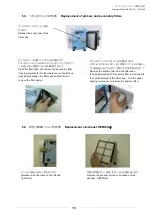
フィルタの交換、メンテナンスのしやすい場所に設置して下さい。
Install the product in a place where filter replacement and maintenance can be performed easily.
本機は歩行面から
0.2
~
2
mの範囲で設置してください。
Install the product in a place 0.2 to 2.0 m from the walking surface.
本機の設置標高は
1,000
m以下です。
The installation height of the product is 1,000 m or less
設置区分は汚染度Ⅱ
(
製造工場
)
です。
The installation classification is “Contamination level
Ⅱ
(manufacturing plant).
1.3
接続
Connection
接続は、確実におこなって下さい。ケーブルを無理に曲げたり、引っ張ったりしないで下さい。
火災・感電の原因になります。
Connect the product securely.
Do not bend or pull cables forcibly. Forcible bending or pulling may cause a fire and electrical shock.
異なった電源で使用しないで下さい。
Use the correct power supply,